Page 471 of 4731
ATC-34
AIR CONDITIONER CONTROL
Revision: 2005 July 2005 FX
Description of Control SystemAJS0014C
The control system consists of input sensors, switches, the unified meter and A/C amp. (microcomputer) and
outputs. The relationship of these components is shown in the figure below:
Control OperationAJS0014D
DISPLAY SCREEN
Displays the operational status of the system.
RJIA1958E
RJIA1959E
Page 488 of 4731
TROUBLE DIAGNOSIS ATC-51
C
D E
F
G H
I
K L
M A
B
AT C
Revision: 2005 July 2005 FX
Auto Amp. Terminals and Reference ValueAJS0014O
Measure voltage between each terminal and ground by referring ter-
minals and reference value for unified meter and A/C amp.
PIN CONNECTOR TERMINAL LAYOUT
TERMINALS AND REFERENCE VALUE FOR UNIFIED METER AND A/C AMP.
RJIA1965E
RJIA1966E
Terminal No. Wire
color Item
Ignition
switch Condition
Voltage
(V)
1 L CAN-H — — —
11 R C A N - L — — —
21 R/W Power supply for BATT OFF — Battery voltage
22 G/R Power supply for IGN ON — Battery voltage
29 B Ground (Power) ON — Approx. 0
30 B Ground ON —- Approx. 0
35 LG/R Power supply for ACC ACC — Battery voltage
39 Y Ambient sensor — — —
40 BR/W In-vehicle sensor — — —
41 P Intake sensor — — —
42 R/Y Compressor ON signal ON A/C switch: ON
(Blower motor operates.) Approx. 0
OFF switch: ON
(A/C system: OFF) Approx. 5
43 G/B A/C LAN signal ON —
HAK0652D
Page 489 of 4731
ATC-52
TROUBLE DIAGNOSIS
Revision: 2005 July 2005 FX
45 PU/W ECV (Electric Control Valve)
signal ON
Self-diagnosis. STEP-4
(Code No. 45)
46 L/W Power supply for IGN2 ON — Battery voltage
49 W/G Sensor ground ON — Approx. 0
50 LG Sunload sensor — — —
53 G Blower motor control signal ON Blower speed: 1st step
54 Y/R Power supply for each door
motor ON — Battery voltage
57 BR/Y Blower motor ON signal ON A/C switch: ON
(Blower motor operates.) Approx. 0
OFF switch: ON
(A/C system: OFF) Approx. 5
Te r m i n a l
No. Wire
color ItemIgnition
switch Condition Voltag e
(V)
RJIA1606E
SJIA0116J
Page 490 of 4731
TROUBLE DIAGNOSIS ATC-53
C
D E
F
G H
I
K L
M A
B
AT C
Revision: 2005 July 2005 FX
Self-diagnosis FunctionAJS0014P
DESCRIPTION
The self-diagnosis system diagnoses sensors, door motors, blower motor, etc. by system line. Refer to appli-
cable sections (items) for details. Shifting from usual control to the self-diagnosis system is accomplished by
starting the engine (turning the ignition switch ON) and pressing OFF switch for at least 5 seconds. The OFF
switch must be pressed within 10 seconds after starting the engine (ignition switch is turned ON). This system
will be canceled by either pressing AUTO switch or turning the ignition switch OFF. Shifting from one step to
another is accomplished by means of pressing temperature switch (driver side), as required.
Shifting from STEP-5 to AUXILIARY MECHANISM is accomplished by means of pressing (fan) UP switch.
RJIA1967E
Page 491 of 4731

ATC-54
TROUBLE DIAGNOSIS
Revision: 2005 July 2005 FX
FUNCTION CONFIRMATION PROCEDURE
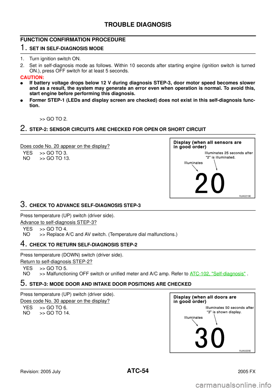
1. SET IN SELF-DIAGNOSIS MODE
1. Turn ignition switch ON.
2. Set in self-diagnosis mode as follows. Within 10 seconds after starting engine (ignition switch is turned ON.), press OFF switch for at least 5 seconds.
CAUTION:
�If battery voltage drops below 12 V during diagnosis STEP-3, door motor speed becomes slower
and as a result, the system may generate an error even when operation is normal. To avoid this,
start engine before performing this diagnosis.
�Former STEP-1 (LEDs and display screen are checked) does not exist in this self-diagnosis func-
tion.
>> GO TO 2.
2. STEP-2: SENSOR CIRCUITS ARE CHECKED FOR OPEN OR SHORT CIRCUIT
Does code No. 20 appear on the display?
YES >> GO TO 3.
NO >> GO TO 13.
3. CHECK TO ADVANCE SELF-DIAGNOSIS STEP-3
Press temperature (UP) switch (driver side).
Advance to self
-diagnosis STEP-3?
YES >> GO TO 4.
NO >> Replace A/C and AV switch. (Temperature dial malfunctions.)
4. CHECK TO RETURN SELF-DIAGNOSIS STEP-2
Press temperature (DOWN) switch (driver side).
Return to self
-diagnosis STEP-2?
YES >> GO TO 5.
NO >> Malfunctioning OFF switch or unified meter and A/C amp. Refer to ATC-102, "
Self-diagnosis" .
5. STEP-3: MODE DOOR AND INTAKE DOOR POSITIONS ARE CHECKED
Press temperature (UP) switch (driver side).
Does code No. 30 appear on the display?
YES >> GO TO 6.
NO >> GO TO 14.
RJIA0219E
RJIA0220E
Page 493 of 4731

ATC-56
TROUBLE DIAGNOSIS
Revision: 2005 July 2005 FX
8. STEP-5: TEMPERATURE OF EACH SENSOR IS CHECKED
1. Press temperature (UP) switch (driver side).
2. Code No. 51 appears on the display.
>> GO TO 9.
9. CHECK AMBIENT SENSOR
Press (DEF) switch one time. Temperature detected by ambient
sensor is indicated on the display.
NOTE:
If temperature shown on display greatly differs from actual tempera-
ture, check sensor circuit first, then inspect sensor.
OK or NG
OK >> GO TO 10.
NG >> Go to Ambient Sensor Circuit. Refer to ATC-104, "
Ambi-
ent Sensor Circuit" .
10. CHECK IN-VEHICLE SENSOR
Press (DEF) switch a second time. Temperature detected by in-
vehicle sensor is indicated on the display.
NOTE:
If temperature shown on display greatly differs from actual tempera-
ture, check sensor circuit first, then inspect sensor.
OK or NG
OK >> GO TO 11.
NG >> Go to In-vehicle Sensor Circuit. Refer to ATC-107, "
In-
vehicle Sensor Circuit" .
11 . CHECK INTAKE SENSOR
Press (DEF) switch a third time. Temperature detected by intake
sensor is indicated on the display.
NOTE:
If temperature shown on display greatly differs from actual tempera-
ture, check sensor circuit first, then inspect sensor.
OK or NG
OK >> GO TO 12.
NG >> Go to Intake Sensor Circuit. Refer to AT C - 11 3 , "
Intake
Sensor Circuit" .
RJIA0223E
RJIA1271E
RJIA1272E
Page 494 of 4731

TROUBLE DIAGNOSIS ATC-57
C
D E
F
G H
I
K L
M A
B
AT C
Revision: 2005 July 2005 FX
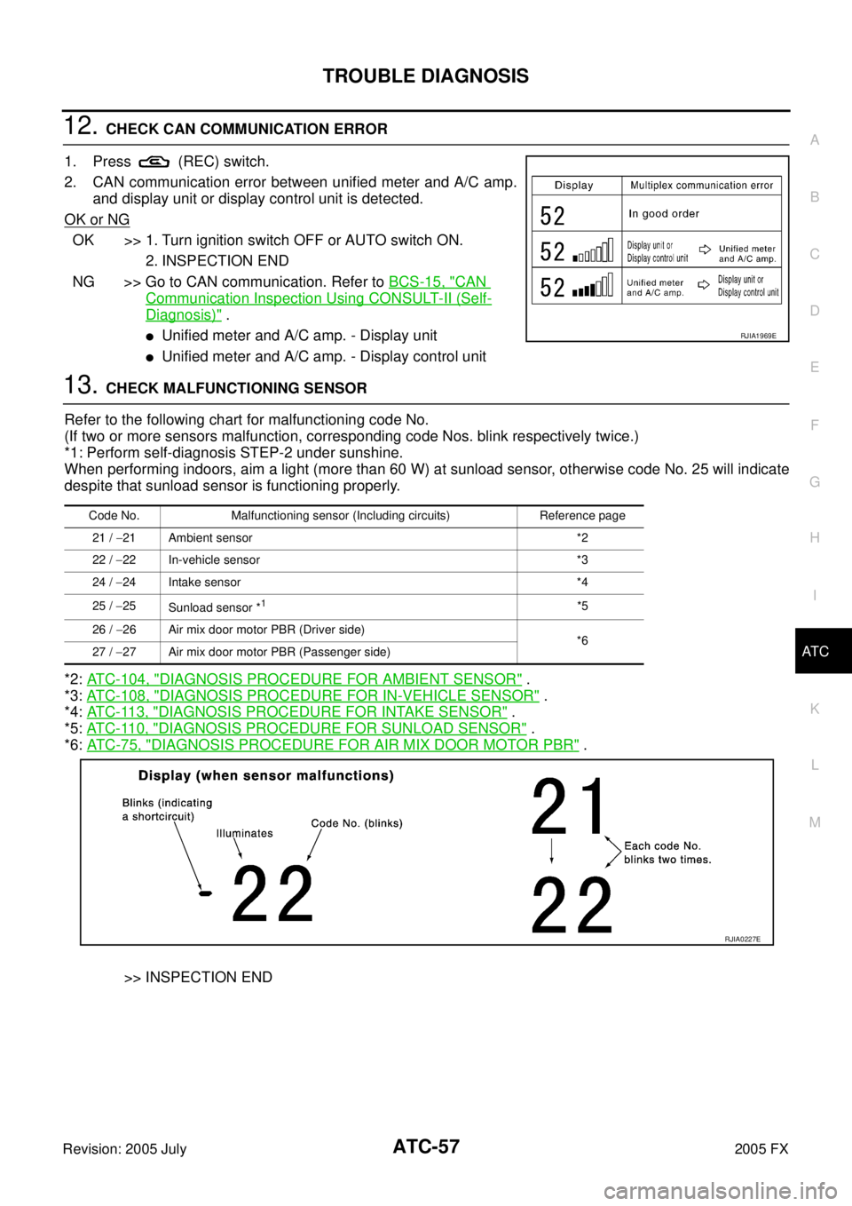
12. CHECK CAN COMMUNICATION ERROR
1. Press (REC) switch.
2. CAN communication error between unified meter and A/C amp. and display unit or display control unit is detected.
OK or NG
OK >> 1. Turn ignition switch OFF or AUTO switch ON. 2. INSPECTION END
NG >> Go to CAN communication. Refer to BCS-15, "
CAN
Communication Inspection Using CONSULT-II (Self-
Diagnosis)" .
�Unified meter and A/C amp. - Display unit
�Unified meter and A/C amp. - Display control unit
13. CHECK MALFUNCTIONING SENSOR
Refer to the following chart for malfunctioning code No.
(If two or more sensors malfunction, corresponding code Nos. blink respectively twice.)
*1: Perform self-diagnosis STEP-2 under sunshine.
When performing indoors, aim a light (more than 60 W) at sunload sensor, otherwise code No. 25 will indicate
despite that sunload sensor is functioning properly.
*2: ATC-104, "
DIAGNOSIS PROCEDURE FOR AMBIENT SENSOR" .
*3: ATC-108, "
DIAGNOSIS PROCEDURE FOR IN-VEHICLE SENSOR" .
*4: AT C - 11 3 , "
DIAGNOSIS PROCEDURE FOR INTAKE SENSOR" .
*5: AT C - 11 0 , "
DIAGNOSIS PROCEDURE FOR SUNLOAD SENSOR" .
*6: AT C - 7 5 , "
DIAGNOSIS PROCEDURE FOR AIR MIX DOOR MOTOR PBR" .
>> INSPECTION END
RJIA1969E
Code No. Malfunctioning sensor (Including circuits) Reference page 21 / −21 Ambient sensor *2
22 / −22 In-vehicle sensor *3
24 / −24 Intake sensor *4
25 / −25
Sunload sensor *
1*5
26 / −26 Air mix door motor PBR (Driver side)
*6
27 / −27 Air mix door motor PBR (Passenger side)
RJIA0227E
Page 501 of 4731

ATC-64
TROUBLE DIAGNOSIS
Revision: 2005 July 2005 FX
COMPONENT DESCRIPTION
Unified Meter and A/C Amp. (Automatic Amplifier)
The unified meter and A/C amp. has a built-in microcomputer which
processes information sent from various sensors needed for air con-
ditioner operation. The air mix door motor, mode door motor, intake
door motor, blower motor and compressor are then controlled.
When the various switches and temperature switch are operated,
data is input to the unified meter and A/C amp. from the display unit/
display control unit using CAN communication.
Self-diagnosis functions are also built into unified meter and A/C
amp. to provide quick check of malfunctions in the auto air condi-
tioner system.
Potentio Temperature Control (PTC)
The PTC is built into the A/C and AV switch. It can be set at an inter-
val of 0.5 °C (1.0 °F) in the 18 °C (60 °F) to 32 °C (90 °F) temperature
range by pressing temperature switch. The set temperature is dis-
played.
DIAGNOSIS PROCEDURE FOR A/C SYSTEM
SYMPTOM: A/C system does not come on.
RJIA1965E
RJIA1982E
RJIA1983E