Page 521 of 4731
ATC-84
TROUBLE DIAGNOSIS
Revision: 2005 July 2005 FX
Magnet Clutch CircuitAJS0014Y
SYMPTOM: Magnet clutch does not engage.
INSPECTION FLOW
*1ATC-113, "Intake Sensor Circuit"*2 ATC-104, "Ambient Sensor Circuit"*3AT C - 5 4 , "FUNCTION CONFIRMA-
TION PROCEDURE", see No. 13.
*4 ATC-85, "
DIAGNOSIS PROCE-
DURE FOR MAGNET CLUTCH"
*5 ATC-96, "TROUBLE DIAGNOSIS
FOR UNUSUAL PRESSURE"
*6AT C - 6 1 , "Operational Check"
*7ATC-54, "FUNCTION CONFIRMA-
TION PROCEDURE", see No. 4 to 6. *8
ATC-42, "
SYMPTOM TABLE"
RJIA2002E
Page 522 of 4731
TROUBLE DIAGNOSIS ATC-85
C
D E
F
G H
I
K L
M A
B
AT C
Revision: 2005 July 2005 FX
SYSTEM DESCRIPTION
Unified meter and A/C amp. controls compressor operation by ambient temperature, intake air temperature
and signal from ECM.
Low Temperature Protection Control
Unified meter and A/C amp. will turn the compressor ON or OFF as determined by a signal detected by ambi-
ent sensor and intake sensor.
When ambient temperature is higher than −2 °C (28 °F), the compres-
sor turns ON. The compressor turns OFF when ambient temperature
is lower than −5 °C (23 °F).
When intake air temperature is higher than 1 °C (34 °F), the compres-
sor turns ON. The compressor turns OFF when intake air tempera-
ture is lower than −5°C (23 °F).
DIAGNOSIS PROCEDURE FOR MAGNET CLUTCH
SYMPTOM: Magnet clutch does not engage when A/C switch is ON.
RHA094GB
SJIA0267E
RJIA2003E
Page 523 of 4731

ATC-86
TROUBLE DIAGNOSIS
Revision: 2005 July 2005 FX
1. CHECK AMBIENT SENSOR AND INTAKE SENSOR CIRCUIT
Check ambient sensor and intake sensor. Refer to AT C - 5 4 , "
FUNCTION CONFIRMATION PROCEDURE" ,
see No. 9 and 11.
OK or NG
OK >> GO TO 2.
NG >>
�Malfunctioning ambient sensor: Refer to ATC-104, "Ambient Sensor Circuit" .
�Malfunctioning intake sensor: Refer to AT C - 11 3 , "Intake Sensor Circuit" .
2. PERFORM AUTO ACTIVE TEST
Refer to PG-24, "
Auto Active Test" .
Does the magnet clutch operate?
YES >>�WITH CONSULT-II
GO TO 5.
�WITHOUT CONSULT-II
GO TO 6.
NO >> Check 10 A fuse (No. 79, located in IPDM E/R), and GO TO 3.
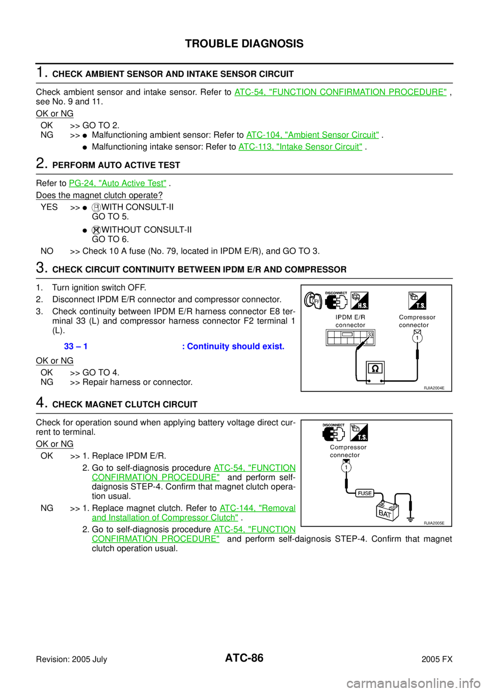
3. CHECK CIRCUIT CONTINUITY BETWEEN IPDM E/R AND COMPRESSOR
1. Turn ignition switch OFF.
2. Disconnect IPDM E/R connector and compressor connector.
3. Check continuity between IPDM E/R harness connector E8 ter- minal 33 (L) and compressor harness connector F2 terminal 1
(L).
OK or NG
OK >> GO TO 4.
NG >> Repair harness or connector.
4. CHECK MAGNET CLUTCH CIRCUIT
Check for operation sound when applying battery voltage direct cur-
rent to terminal.
OK or NG
OK >> 1. Replace IPDM E/R. 2. Go to self-diagnosis procedure AT C - 5 4 , "
FUNCTION
CONFIRMATION PROCEDURE" and perform self-
daignosis STEP-4. Confirm that magnet clutch opera-
tion usual.
NG >> 1. Replace magnet clutch. Refer to ATC-144, "
Removal
and Installation of Compressor Clutch" .
2. Go to self-diagnosis procedure AT C - 5 4 , "
FUNCTION
CONFIRMATION PROCEDURE" and perform self-daignosis STEP-4. Confirm that magnet
clutch operation usual.
33 – 1 : Continuity should exist.
RJIA2004E
RJIA2005E
Page 525 of 4731

ATC-88
TROUBLE DIAGNOSIS
Revision: 2005 July 2005 FX
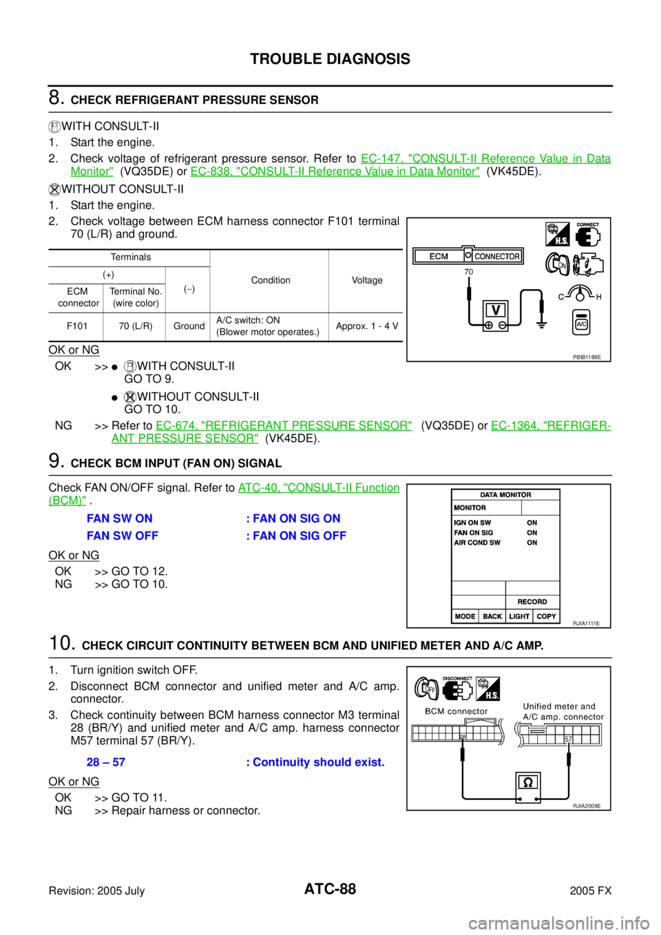
8. CHECK REFRIGERANT PRESSURE SENSOR
WITH CONSULT-II
1. Start the engine.
2. Check voltage of refrigerant pressure sensor. Refer to EC-147, "
CONSULT-II Reference Value in Data
Monitor" (VQ35DE) or EC-838, "CONSULT-II Reference Value in Data Monitor" (VK45DE).
WITHOUT CONSULT-II
1. Start the engine.
2. Check voltage between ECM harness connector F101 terminal 70 (L/R) and ground.
OK or NG
OK >>�WITH CONSULT-II
GO TO 9.
�WITHOUT CONSULT-II
GO TO 10.
NG >> Refer to EC-674, "
REFRIGERANT PRESSURE SENSOR" (VQ35DE) or EC-1364, "REFRIGER-
ANT PRESSURE SENSOR" (VK45DE).
9. CHECK BCM INPUT (FAN ON) SIGNAL
Check FAN ON/OFF signal. Refer to AT C - 4 0 , "
CONSULT-II Function
(BCM)" .
OK or NG
OK >> GO TO 12.
NG >> GO TO 10.
10. CHECK CIRCUIT CONTINUITY BETWEEN BCM AND UNIFIED METER AND A/C AMP.
1. Turn ignition switch OFF.
2. Disconnect BCM connector and unified meter and A/C amp. connector.
3. Check continuity between BCM harness connector M3 terminal 28 (BR/Y) and unified meter and A/C amp. harness connector
M57 terminal 57 (BR/Y).
OK or NG
OK >> GO TO 11.
NG >> Repair harness or connector.
Te r m i n a l s
Condition Voltage
(+)
( − )
ECM
connector Terminal No.
(wire color)
F101 70 (L/R) Ground A/C switch: ON
(Blower motor operates.) Approx. 1 - 4 V
PBIB1188E
FAN SW ON : FAN ON SIG ON
FAN SW OFF : FAN ON SIG OFF
R J I A 1111 E
28 – 57 : Continuity should exist.
RJIA2009E
Page 527 of 4731
ATC-90
TROUBLE DIAGNOSIS
Revision: 2005 July 2005 FX
COMPONENT INSPECTION
Refrigerant Pressure Sensor
The refrigerant pressure sensor is attached to the condenser.
Make sure that the A/C refrigerant pressure and the sensor output
voltage are within the specified range as shown in the A/C operating
condition figure. Refer to EC-674, "
REFRIGERANT PRESSURE
SENSOR" (VQ35DE) or EC-1364, "REFRIGERANT PRESSURE
SENSOR" (VK45DE).
RJIA2011E
RJIA2954E
Page 534 of 4731

TROUBLE DIAGNOSIS ATC-97
C
D E
F
G H
I
K L
M A
B
AT C
Revision: 2005 July 2005 FX
High-pressure Side is Too Low and Low-pressure Side is Too High
Both High- and Low-pressure Sides are Too Low
Gauge indication Refrigerant cycle Probable cause Corrective action
High-pressure side is too low and
low-pressure side is too high. High- and low-pressure sides
become equal soon after com-
pressor operation stops. Compressor pressure opera-
tion is improper.
↓
Damaged inside compressor
packings. Replace compressor.
No temperature difference
between high- and low-pres-
sure sides. Compressor pressure opera-
tion is improper.
↓
Damaged inside compressor
packings. Replace compressor.
AC356A
Gauge indication Refrigerant cycle Probable cause Corrective action
Both high- and low-pressure sides
are too low.
�There is a big temperature
difference between liquid
tank outlet and inlet. Outlet
temperature is extremely
low.
�Liquid tank inlet and expan-
sion valve are frosted. Liquid tank inside is slightly
clogged.
�Replace liquid tank.
�Check lubricant for contami-
nation.
�Temperature of expansion
valve inlet is extremely low
as compared with areas
near liquid tank.
�Expansion valve inlet may
be frosted.
�Temperature difference
occurs somewhere in high-
pressure side. High-pressure pipe located
between liquid tank and
expansion valve is clogged.
�Check and repair malfunc-
tioning parts.
�Check lubricant for contami-
nation.
Expansion valve and liquid
tank are warm or slightly cool
when touched. Low refrigerant charge.
↓
Leaking fittings or compo-
nents. Check refrigerant for leaks.
Refer to ATC-158, "
Checking
for Refrigerant Leaks" .
There is a big temperature dif-
ference between expansion
valve inlet and outlet while the
valve itself is frosted. Expansion valve closes a little
compared with the specifica-
tion.
↓
1. Improper expansion valve adjustment.
2. Malfunctioning expansion valve.
3. Outlet and inlet may be clogged.
�Remove foreign particles by
using compressed air.
�Replace expansion valve.
�Check lubricant for contami-
nation.
An area of the low-pressure
pipe is colder than areas near
the evaporator outlet. Low-pressure pipe is clogged
or crushed.
�Check and repair malfunc-
tioning parts.
�Check lubricant for contami-
nation.
Air flow volume is not enough
or is too low. Evaporator is frozen.
�Check intake sensor circuit.
Refer to AT C - 11 3 , "
Intake
Sensor Circuit" .
�Replace compressor.
�Repair evaporator fins.
�Replace evaporator.
�Refer to AT C - 7 9 , "Blower
Motor Circuit" .
AC353A
Page 537 of 4731
ATC-100
TROUBLE DIAGNOSIS
Revision: 2005 July 2005 FX
Insufficient HeatingAJS00150
SYMPTOM: Insufficient heating
INSPECTION FLOW
*1ATC-61, "Operational Check"*2AT C - 7 3 , "Air Mix Door Motor Circuit"*3ATC-54, "FUNCTION CONFIRMA-
TION PROCEDURE", see No. 4 to
6.
*4 ATC-54, "
FUNCTION CONFIRMA-
TION PROCEDURE", see No. 13. *5
AT C - 6 6 , "
LAN System Circuit"*6ATC-79, "Blower Motor Circuit"
*7 EC-208, "DTC P0117, P0118 ECT
SENSOR" (VQ35DE) or EC-914,
"DTC P0117, P0118 ECT SEN-
SOR" (VK45DE) *8
CO-11, "
Changing Engine Coolant"
(VQ35DE) or CO-37, "
Changing
Engine Coolant" (VK45DE) *9
CO-15, "
Checking Radiator Cap"
(VQ35DE) or CO-43, "
Checking
Radiator Cap" (VK45DE)
RJIA2013E
Page 539 of 4731
ATC-102
TROUBLE DIAGNOSIS
Revision: 2005 July 2005 FX
Self-diagnosisAJS00152
SYMPTOM: Self-diagnosis cannot be performed.
INSPECTION FLOW
*1 Compressor Clutch, ATC-144,
"REMOVAL"
*2 Compressor Clutch, ATC-146,
"INSTALLATION"
*3AT C - 2 7 , "Maintenance of Lubricant
Quantity in Compressor"
*4ATC-61, "Operational Check"*5 EM-15, "Checking Drive Belts"
(VQ35DE) or EM-173, "
Checking
Drive Belts" (VK45DE)
*1 ATC-63, "
Power Supply and Ground
Circuit for Auto Amp."
*2 ATC-104, "Ambient Sensor Circuit"*3ATC-107, "In-vehicle Sensor Circuit"
*4ATC-110, "Sunload Sensor Circuit"*5 ATC-113, "Intake Sensor Circuit"*6AT C - 7 3 , "Air Mix Door Motor Circuit"
*7ATC-61, "Operational Check"*8 ATC-42, "SYMPTOM TABLE"
RJIA2014E