Page 385 of 4731

AT-302
DISASSEMBLY
Revision: 2005 July 2005 FX
48. Remove needle bearing from transmission case.
49. Remove revolution sensor from transmission case. CAUTION:
�Do not subject it to impact by dropping or hitting it.
�Do not disassemble.
�Do not allow metal filings, etc. to get on the sensor's front
edge magnetic area.
�Do not place in an area affected by magnetism.
50. Remove reverse brake snap ring (fixing plate) using 2 flat- bladed screwdrivers.
NOTE:
Press out snap ring from the transmission case oil pan side gap
using a flat-bladed screwdriver, and remove it using another
screwdriver.
51. Remove reverse brake retaining plate from transmission case.
�Check facing for burns, cracks or damage. If necessary,
replace the plate.
52. Remove N-spring from transmission case.
53. Remove reverse brake drive plates, driven plates and dish plate from transmission case.
�Check facing for burns, cracks or damage. If necessary,
replace the plate.
SCIA5031E
SCIA2320E
SCIA5032E
SCIA5214E
SCIA2322E
Page 416 of 4731
ASSEMBLY AT-333
D E
F
G H
I
J
K L
M A
B
AT
Revision: 2005 July 2005 FX
22. Measure clearance between retaining plate and snap ring. If not
within specified clearance, select proper retaining plate.
23. Install needle bearing to transmission case. CAUTION:
Apply petroleum jelly to needle bearing.
24. Install revolution sensor to transmission case. CAUTION:
�Do not subject it to impact by dropping or hitting it.
�Do not disassemble.
�Do not allow metal filings, etc., to get on the sensor's
front edge magnetic area.
�Do not place in an area affected by magnetism.
25. As shown in the figure, use the drift to drive rear oil seal into the rear extension (2WD models) or adapter case (AWD models)
until it is flush.
CAUTION:
�Apply ATF to rear oil seal.
�Do not reuse rear oil seal. Specified clearance “A”:
Standard: 0.7 - 1.1mm (0.028 - 0.043 in)
Retaining plate: Refer to AT- 3 5 3 , "
Reverse Brake" .
SCIA3129E
SCIA5031E
: 5.8 N·m (0.59 kg-m, 51 in-lb)
SCIA2320E
SCIA5477E
Page 428 of 4731
ASSEMBLY AT-345
D E
F
G H
I
J
K L
M A
B
AT
Revision: 2005 July 2005 FX
6. Install O-ring to input clutch assembly.
CAUTION:
�Do not reuse O-ring.
�Apply ATF to O-ring.
7. Install converter housing to transmission case. CAUTION:
Do not reuse self-sealing bolt.
8. Make sure that brake band does not close turbine revolution sensor hole.
9. Install control valve with TCM.
a. Connect TCM connector and park/neutral position switch con- nector.
SCIA5011E
Converter housing mounting bolt:
: 52 N·m (5.3 kg-m, 38 ft-lb)
Self-sealing bolt: : 61 N·m (6.2 kg-m, 45 ft-lb)
SCIA3427E
SCIA5034E
SCIA5449E
Page 429 of 4731
AT-346
ASSEMBLY
Revision: 2005 July 2005 FX
b. Install A/T assembly harness connector from control valve with
TCM.
c. Connect TCM connectors.
d. Install O-ring to A/T assembly harness connector. CAUTION:
�Do not reuse O-ring.
�Apply ATF to O-ring.
e. Install A/T fluid temperature sensor 2 to bracket.
f. Install A/T fluid temperature sensor 2 (with bracket) in control valve with TCM.
CAUTION:
Adjust bolt hole of bracket to bolt hole of control valve.
SCIA5450E
SCIA5447E
SCIA5155E
SCIA5264E
: 7.9 N·m (0.81 kg-m, 70 in-lb)
SCIA5301E
Page 430 of 4731
ASSEMBLY AT-347
D E
F
G H
I
J
K L
M A
B
AT
Revision: 2005 July 2005 FX
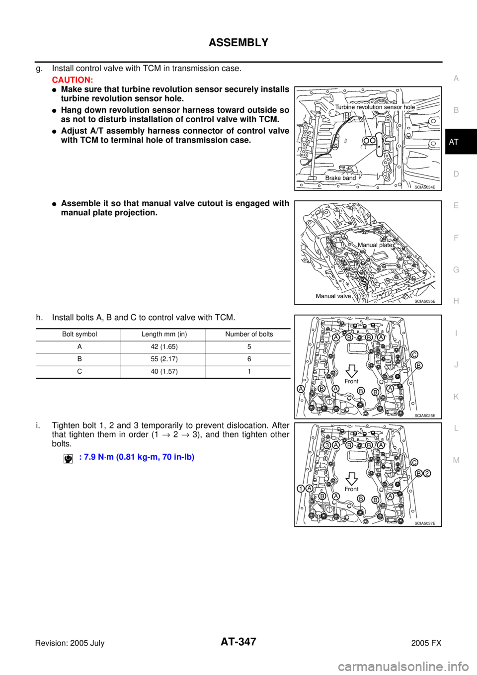
g. Install control valve with TCM in transmission case.
CAUTION:
�Make sure that turbine revolution sensor securely installs
turbine revolution sensor hole.
�Hang down revolution sensor harness toward outside so
as not to disturb installation of control valve with TCM.
�Adjust A/T assembly harness connector of control valve
with TCM to terminal hole of transmission case.
�Assemble it so that manual valve cutout is engaged with
manual plate projection.
h. Install bolts A, B and C to control valve with TCM.
i. Tighten bolt 1, 2 and 3 temporarily to prevent dislocation. After that tighten them in order (1 → 2 → 3), and then tighten other
bolts.
SCIA5034E
SCIA5035E
Bolt symbol Length mm (in) Number of bolts
A 42 (1.65) 5
B 55 (2.17) 6
C 40 (1.57) 1
: 7.9 N·m (0.81 kg-m, 70 in-lb)
SCIA5025E
SCIA5037E
Page 431 of 4731
AT-348
ASSEMBLY
Revision: 2005 July 2005 FX
10. Connect A/T fluid temperature sensor 2 connector.
11. Securely fasten terminal cord assembly and A/T fluid tempera-
ture sensor 2 harness with terminal clips.
12. Connect revolution sensor connector.
13. Securely fasten revolution sensor 2 harness with terminal clips.
14. Pull down A/T assembly harness connector. CAUTION:
Be careful not to damage connector.
SCIA5023E
SCIA5446E
SCIA5024E
SCIA5293E
SCIA5299E
Page 435 of 4731

Revision: 2005 July 2005 FX
Vehicle Speed at Which Lock-up Occurs/ReleasesACS002S4
2WD MODELS
�At closed throttle, the accelerator opening is less than 1/8")
AT-352
SERVICE DATA AND SPECIFICATIONS (SDS)
Revision: 2005 July 2005 FX
Vehicle Speed at Which Lock-up Occurs/ReleasesACS002S4
2WD MODELS
�At closed throttle, the accelerator opening is less than 1/8 condition. (Closed throttle position signal: OFF)
�At half throttle, the accelerator opening is 4/8 of the full opening.
AW D M OD E LS
�At closed throttle, the accelerator opening is less than 1/8 condition. (Closed throttle position signal: OFF)
�At half throttle, the accelerator opening is 4/8 of the full opening.
�At closed throttle, the accelerator opening is less than 1/8 condition. (Closed throttle position signal: OFF)
�At half throttle, the accelerator opening is 4/8 of the full opening.
Stall SpeedACS002S6
Line PressureACS002S7
A/T Fluid Temperature SensorACS00858
Engine model VQ35DE
Throttle position Vehicle speed km/h (MPH)
Lock-up ON Lock-up OFF
Closed throttle 65 - 73 (40 - 45) 62 - 70 (39 - 43)
Half throttle 196 - 204 (122 - 127) 153 - 161 (95 - 100)
Engine model VQ35DE
Throttle position Vehicle speed km/h (MPH)
Lock-up ON Lock-up OFF
Closed throttle 59 - 67 (37 - 42) 56 - 64 (35 - 40)
Half throttle 178 - 186 (111 - 116) 139 - 147 (86 - 91)
Engine model VK45DE
Throttle position Vehicle speed km/h (MPH)
Lock-up ON Lock-up OFF
Closed throttle 66 - 74 (41 - 46) 53 - 61 (33 - 38)
Half throttle 191 - 199 (119 - 124) 136 - 144 (85 - 89)
Engine model VQ35DE
Stall speed 2,200 - 2,400 rpm
Engine model VK45DE
Stall speed 1,950 - 2,250 rpm
Engine speed Line pressure [kPa (kg/cm2 , psi)]
R position D and M positions
At idle speed 425 - 465 (4.3 - 4.8, 62 - 67) 379 - 428 (3.9 - 4.4, 55 - 62)
At stall speed 1,605 - 1,950 (16.4 - 19.9, 233 - 283) 1,310 - 1,500 (13.4 - 15.3, 190 - 218)
Name Condition CONSULT-II “DATA MONITOR” (Approx.) (V) Resistance (Approx.) (k Ω)
A/T fluid temperature sensor 1 0
°C (32 °F) 3.3 15
20 °C (68 °F) 2.7 6.5
80 °C (176 °F) 0.9 0.9
A/T fluid temperature sensor 2 0
°C (32 °F) 3.3 10
20 °C (68 °F) 2.5 4
80 °C (176 °F) 0.7 0.5
Page 436 of 4731
 AT-353
D E
F
G H
I
J
K L
M A
B
AT
Revision: 2005 July 2005 FX
Turbine Revolution SensorACS00859
Vehicle Speed Sensor A/T (Revolution Sensor)ACS0085A
R")
SERVICE DATA AND SPECIFICATIONS (SDS) AT-353
D E
F
G H
I
J
K L
M A
B
AT
Revision: 2005 July 2005 FX
Turbine Revolution SensorACS00859
Vehicle Speed Sensor A/T (Revolution Sensor)ACS0085A
Reverse BrakeACS0085B
*: Always check with the Parts Department for the latest parts information.
To ta l E n d P l a yACS0085C
BEARING RACE FOR ADJUSTING TOTAL END PLAY
*: Always check with the Parts Department for the latest parts information. Name Condition Data (Approx.)
Turbine revolution
sensor 1 When running at 50 km/h (31 MPH) in 4th speed with the closed throttle position switch
“OFF”. 1.3 (kHz)
Turbine revolution
sensor 2 When moving at 20 km/h (12 MPH) in 1st speed with the closed throttle position switch
“OFF”.
Name Condition Data (Approx.)
Revolution sensor When moving at 20 km/h (12 MPH). 185 (Hz)
Thickness of retaining plates Thickness mm (in) Part number*
4.2 (0.165)
4.4 (0.173)
4.6 (0.181)
4.8 (0.189)
5.0 (0.197)
5.2 (0.205) 31667 90X14
31667 90X15
31667 90X16
31667 90X17
31667 90X18
31667 90X19
Total end play mm (in) 0.25 - 0.55 (0.0098 - 0.0217)
Thickness mm (in) Part number*
1.2 (0.047)
1.4 (0.055)
1.6 (0.063)
1.8 (0.071)
2.0 (0.079) 31435 90X02
31435 90X03
31435 90X04
31435 90X05
31435 90X06