Page 4283 of 4731

PS-8
POWER STEERING FLUID
Revision: 2005 July 2005 FX
POWER STEERING FLUIDPFP:KLF20
Checking Fluid LevelAGS000GT
�Stop engine before performing a fluid level check.
�Ensure that fluid level is between the MAX range and MIN level.
�Because fluid level differs within the HOT range and the COLD
range, check it carefully.
CAUTION:
�Do not overfill the Max level.
�Do not reuse any used power steering fluid.
�Recommended fluid is Genuine NISSAN PSF or equivalent.
Checking Fluid LeakageAGS000GU
Check the hydraulic piping lines for improper attachment and for
leaks, cracks, damage, loose connections, chafing or deterioration.
1. Run engine until fluid temperature reaches 50 to 80 ° C (122 to
176 °F) in reservoir tank. Keep engine speed idle.
2. Turn steering wheel right-to-left several times.
3. Hold steering wheel at each “lock” position for five seconds to check fluid leakage.
CAUTION:
Do not hold steering wheel in a locked position for more
than 10 seconds. (There is the possibility that oil pump may
be damaged.)
4. If fluid leakage at connections is noticed, then loosen flare nut and then retighten. Do not over tighten con- nector as this can damage O-ring, washer and connector.
5. If fluid leakage from oil pump is noticed, check oil pump. Refer to PS-31, "
POWER STEERING OIL
PUMP" .
6. Check steering gear boots for accumulation of fluid indicating a from steering gear.
Air Bleeding Hydraulic SystemAGS000GV
Incomplete air bleeding causes the following. When this happens, bleed air again.
�Generation of air bubbles in reservoir tank.
�Generation of clicking noise in oil pump.
�Excessive buzzing in oil pump.
NOTE:
When vehicle is stationary or while steering wheel is being turned slowly, some noise may be heard from
oil pump or gear. This noise is normal and does not affect any system.
1. Stop engine, and then turn steering wheel fully to right and left several times. CAUTION:
Do not allow steering fluid reservoir tank to go below the low-level line. Check tank frequently and
add fluid as needed.
2. Run engine at idle speed. Turn steering wheel fully to the right and then fully to the left, and keep for about three seconds. Then check whether a fluid leakage has occurred.
3. Repeat the 2nd procedure several times at about three seconds intervals. CAUTION:
Do not hold steering wheel in the locked position more than 10 seconds. (There is the possibility
that oil pump may be damaged.)
4. Check generation of air bubbles and cloud in fluid. HOT : Fluid temperatures from 50 to 80
°C (122 to
176 °F)
COLD : Fluid temperatures from 0 to 30 °C (32 to 86 °F)
SGIA0232J
SGIA0506E
Page 4285 of 4731

PS-10
STEERING WHEEL
Revision: 2005 July 2005 FX
STEERING WHEELPFP:48430
On-Vehicle Inspection and ServiceAGS000GW
CHECKING CONDITION OF INSTALLATION
�Check installation condition of steering gear assembly, front suspension, axle and steering column.
�Check if movement exists when steering wheel is moved up and down, to the left and right and to the axial
direction.
�Check if the mounting bolts for steering gear assembly are loose
or not. Refer to PS-19, "
POWER STEERING GEAR AND LINK-
AGE" .
CHECKING STEERING WHEEL PLAY
1. Set tires to the straight ahead, start engine, then turn steering wheel to the left and right lightly, and mea-
sure steering wheel movement on the outer circumference when steering wheel is turned up to the point
where tires start moving.
CHECKING NEUTRAL POSITION ON STEERING WHEEL
Check neutral position on steering wheel after confirming that front wheel alignment is correct. Refer to FSU-
6, "Wheel Alignment Inspection" .
1. Set vehicle to the straight direction, check if steering wheel is in the neutral position.
2. If it is not in the neutral position, remove steering wheel and reinstall it correctly.
3. If the neutral position cannot adjust in the two teeth of steering gear assembly, loosen outer socket lock nuts of steering outer sockets, then adjust outer socket by the same amount in the opposite direction.
CHECKING STEERING WHEEL TURNING FORCE
1. Park vehicle on a level and dry surface, set parking brake.
2. Remove driver air bag module from steering wheel. Refer to SRS-35, "
DRIVER AIR BAG MODULE" .
3. Start engine at idle, make steering fluid reach to normal operat- ing temperature [50 to 80 °C (122 to 176 °F)], then check steering
wheel turning torque with pre-load gauge (SST).
4. If steering wheel turning force is out of the specification, check relief hydraulic pressure of oil pump. Refer to PS-31, "
POWER
STEERING OIL PUMP" .
End play of the axle direction for steering wheel : 0 mm (0 in)
SGIA0546E
Steering wheel play on the outer circumference : 0
− 35 mm (0 − 1.38 in)
Turning torque : 7.45 N·m (0.76 kg-m, 66 in-lb) or less
SGIA0459E
Page 4286 of 4731

STEERING WHEEL PS-11
C
D E
F
H I
J
K L
M A
B
PS
Revision: 2005 July 2005 FX
CHECKING FRONT WHEEL TURNING ANGLE
�Check front wheel turning angle after the toe-in inspection.
Place front wheels on turning radius gauges and rear wheels on
stands so that vehicle can be level. Check the maximum inner
and outer wheel turning angles for LH and RH road wheels.
�Start engine and run at idle, turn steering wheel all the way right
and left, measure the turning angle.
�Any turning angles are not adjustable. If any of steering angles
are out of the specification, check if the following parts are wear
or damaged.
–Steering gear
–St ee rin g c o lum n
–Front suspension components
If found that they are worn or damaged, replace them with new ones respectively.
Removal and InstallationAGS000GX
Refer to PS-12, "STEERING COLUMN" .
FAA0016D
Tire Size 18 inch and 20 inch
Inner wheel (Angle: A) Minimum 32
°00’ (32.0 °)
Nominal 35 °00’ (35.0 °)
Maximum 36 °00’ (36.0 °)
Outer wheel (Angle: B) Nominal 30 °00’ (30.0 °)
SGIA0055E
Page 4287 of 4731

PS-12
STEERING COLUMN
Revision: 2005 July 2005 FX
STEERING COLUMNPFP:48810
Removal and InstallationAGS000GY
CAUTION:
�Care must be taken not to give axial impact to steering column assembly during removal and
installation.
�Care must be taken not to move steering gear during removal of steering column assembly.
REMOVAL
1. Set vehicle to the straight ahead-direction.
2. Remove driver air bag module from steering wheel. Refer to SRS-35, "
DRIVER AIR BAG MODULE" .
3. Disconnect steering switch connector, remove steering wheel lock nut, then remove steering wheel. Refer to SRS-37, "
SPIRAL CABLE" .
4. Remove steering column cover. Refer to IP-10, "
INSTRUMENT PANEL ASSEMBLY" .
5. Remove combination switch & spiral cable from steering column assembly. Refer to SRS-37, "
SPIRAL
CABLE" .
6. Remove instrument lower panel (driver side). Refer to IP-10, "
INSTRUMENT PANEL ASSEMBLY" .
7. Remove combination meter. Refer to IP-10, "
INSTRUMENT PANEL ASSEMBLY" .
1. Steering wheel lock nut 2. Steering wheel 3. Lid
4. Combination switch & spiral cable 5. Steering column assembly 6. Collar
7. Hole cover seal 8. Clamp 9. Hole cover
10. Lower shaft 11. Lower joint 12. Steering column assembly (with Automatic Drive Positioner)
SGIA1430E
Page 4289 of 4731

PS-14
STEERING COLUMN
Revision: 2005 July 2005 FX
INSPECTION AFTER REMOVAL
�Check if there is something wrong with jacket tube of steering column assembly and collar etc. And then if
they are damaged, replace with new one.
�If vehicle has a collision light shocked, check column length “L”
as shown in the figure. Then if it is out of the specified value,
replace with new one.
�Check the turning torque of steering column with preload gauge
(SST). If it is out of the specified value, repair it or replace with
new one.
INSTALLATION
�Refer to PS-12, "Removal and Installation" for tightening torque. Install in the reverse order of removal.
NOTE:
Refer to component parts location and do not reuse non-reusable parts.
�After removing/installing or replacing steering components, check wheel alignment. Refer to FSU-6,
"Wheel Alignment Inspection" .
�After adjusting wheel alignment, adjust neutral position of steering angle sensor. Refer to BRC-6, "Adjust-
ment of Steering Angle Sensor Neutral Position" .
INSPECTION AFTER INSTALLATION
�Check tilt and telescopic mechanism operating range “L1 ”, “L2 ”
as shown in the figure.
�Check if steering wheel operation can turn to the end of the left
and right smoothly. Steering column length “L”: 572 mm (22.52 in)
Turning torque : 0 − 0.2 N·m (0 − 0.021 kg-m, 0 − 1 in-lb)
SGIA0556E
Tilt operating range “L1 ” : 28 - 32 mm (1.1 - 1.26 in)
Telescopic operating range
“L
2 ” : 18 - 22 mm (0.71 - 0.87 in)
SGIA1431E
Page 4294 of 4731

POWER STEERING GEAR AND LINKAGE PS-19
C
D E
F
H I
J
K L
M A
B
PS
Revision: 2005 July 2005 FX
POWER STEERING GEAR AND LINKAGEPFP:49001
Removal and InstallationAGS000H0
CAUTION:
Spiral cable may snap due to steering operation if steering column is separated from steering gear
assembly. Therefore fix steering wheel with a string to avoid turns.
REMOVAL
1. Set wheels in the straight-ahead position.
2. Remove tires from vehicle with power tool.
3. Remove undercover with power tool.
4. Confirm slit of lower joint fits with the projection on rear cover cap, furthermore marking position on steering gear assembly
nearly fits with the projection on rear cover cap.
5. Remove cotter pin at steering outer socket, then loosen mount- ing nut.
6. Use a ball joint remover (SST) to remove steering outer socket from steering knuckle. Be careful not to damage ball joint boot.
CAUTION:
Tighten temporarily mounting nut to prevent damage to
threads and to prevent ball joint remover (SST) from com-
ing off.
1. Cotter pin 2. Steering gear assembly 3. Washer
4. Clip
SGIA1432E
SGIA0539E
SDIA1434E
Page 4295 of 4731
PS-20
POWER STEERING GEAR AND LINKAGE
Revision: 2005 July 2005 FX
7. Remove oil pipings (high pressure side and low pressure side)
from steering gear assembly, then drain fluid from pipings.
8. Remove mounting bolt of steering hydraulic piping bracket from steering gear assembly.
9. Remove mounting bolt (lower side) of lower joint.
10. Remove mounting bolts of steering gear assembly with power tool, and then remove steering gear assembly from vehicle.
INSTALLATION
�Refer to PS-19, "Removal and Installation" for tightening torque. Install in the reverse order of removal.
NOTE:
Refer to component parts location and do not reuse non-reusable parts.
�After removing/installing or replacing steering components, check wheel alignment. Refer to FSU-6,
"Wheel Alignment Inspection" .
�After adjusting wheel alignment, adjust neutral position of steering angle sensor. Refer to BRC-6, "Adjust-
ment of Steering Angle Sensor Neutral Position" .
SGIA0541E
SGIA0545E
SGIA0542E
SGIA0546E
Page 4296 of 4731
POWER STEERING GEAR AND LINKAGE PS-21
C
D E
F
H I
J
K L
M A
B
PS
Revision: 2005 July 2005 FX
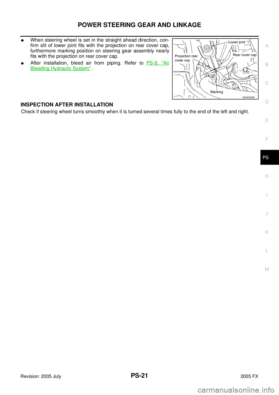
�When steering wheel is set in the straight ahead direction, con-
firm slit of lower joint fits with the projection on rear cover cap,
furthermore marking position on steering gear assembly nearly
fits with the projection on rear cover cap.
�After installation, bleed air from piping. Refer to PS-8, "Air
Bleeding Hydraulic System" .
INSPECTION AFTER INSTALLATION
Check if steering wheel turns smoothly when it is turned several times fully to the end of the left and right.
SGIA0539E

from steering gear assembly, then drain fluid from pipings.
8. Remo")