Page 4711 of 4731
WT-18
TROUBLE DIAGNOSES
Revision: 2005 July 2005 FX
Transmitter Wake Up OperationAES000Z6
WITH ACTIVATION TOOL
1. With the activation tool (J-45295) pushed against the front-left
transmitter, press the button for 5 seconds.
�When ignition switch ON, as the low tire pressure warning
lamp blinks per the following diagram, the respective transmit-
ter then must be woken up.
2. Register the ID of wheel that warning lamp flashes. When wake up of registered wheel has been com- pleted, turn signal lamp flashes two times.
3. After completing wake up all transmitters, make sure low tire pressure warning lamp goes out.
SEIA0460E
SEIA0378E
Page 4712 of 4731

TROUBLE DIAGNOSES WT-19
C
D
F
G H
I
J
K L
M A
B
WT
Revision: 2005 July 2005 FX
Self-DiagnosisAES000Z7
DESCRIPTION
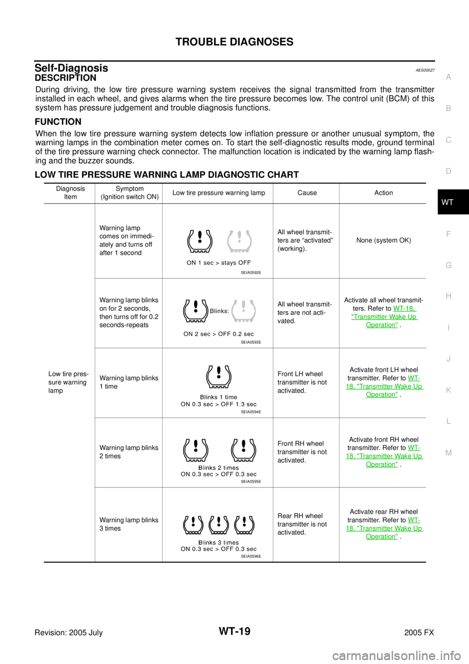
During driving, the low tire pressure warning system receives the signal transmitted from the transmitter
installed in each wheel, and gives alarms when the tire pressure becomes low. The control unit (BCM) of this
system has pressure judgement and trouble diagnosis functions.
FUNCTION
When the low tire pressure warning system detects low inflation pressure or another unusual symptom, the
warning lamps in the combination meter comes on. To start the self-diagnostic results mode, ground terminal
of the tire pressure warning check connector. The malfunction location is indicated by the warning lamp flash-
ing and the buzzer sounds.
LOW TIRE PRESSURE WARNING LAMP DIAGNOSTIC CHART
Diagnosis
Item Symptom
(Ignition switch ON) Low tire pressure warning lamp Cause Action
Low tire pres-
sure warning
lamp Warning lamp
comes on immedi-
ately and turns off
after 1 second All wheel transmit-
ters are “activated”
(working). None (system OK)
Warning lamp blinks
on for 2 seconds,
then turns off for 0.2
seconds-repeats All wheel transmit-
ters are not acti-
vated. Activate all wheel transmit-
ters. Refer to WT-18,
"Transmitter Wake Up
Operation" .
Warning lamp blinks
1 time Front LH wheel
transmitter is not
activated. Activate front LH wheel
transmitter. Refer to WT-
18, "Transmitter Wake Up
Operation" .
Warning lamp blinks
2 times Front RH wheel
transmitter is not
activated. Activate front RH wheel
transmitter. Refer to WT-
18, "Transmitter Wake Up
Operation" .
Warning lamp blinks
3 times Rear RH wheel
transmitter is not
activated. Activate rear RH wheel
transmitter. Refer to WT-
18, "Transmitter Wake Up
Operation" .
SEIA0592E
SEIA0593E
SEIA0594E
SEIA0595E
SEIA0596E
Page 4713 of 4731

WT-20
TROUBLE DIAGNOSES
Revision: 2005 July 2005 FX
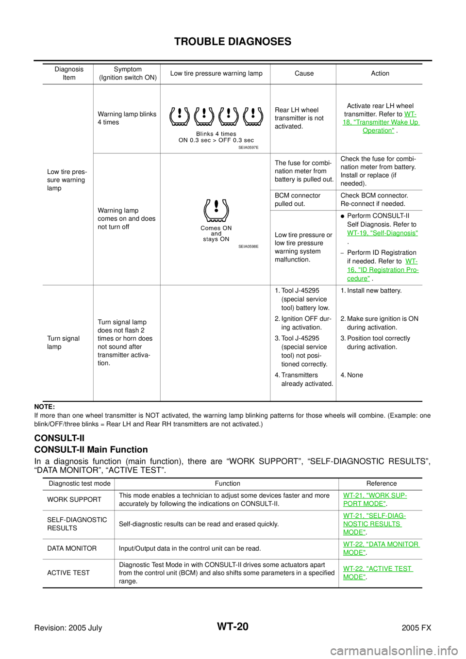
NOTE:
If more than one wheel transmitter is NOT activated, the warning lamp blinking patterns for those wheels will combine. (Example : one
blink/OFF/three blinks = Rear LH and Rear RH transmitters are not activated.)
CONSULT-II
CONSULT-II Main Function
In a diagnosis function (main function), there are “WORK SUPPORT”, “SELF-DIAGNOSTIC RESULTS”,
“DATA MONITOR”, “ACTIVE TEST”.
Low tire pres-
sure warning
lamp Warning lamp blinks
4 times Rear LH wheel
transmitter is not
activated. Activate rear LH wheel
transmitter. Refer to WT-
18, "Transmitter Wake Up
Operation" .
Warning lamp
comes on and does
not turn off The fuse for combi-
nation meter from
battery is pulled out. Check the fuse for combi-
nation meter from battery.
Install or replace (if
needed).
BCM connector
pulled out. Check BCM connector.
Re-connect if needed.
Low tire pressure or
low tire pressure
warning system
malfunction.
�Perform CONSULT-II
Self Diagnosis. Refer to
WT-19, "
Self-Diagnosis"
.
–Perform ID Registration
if needed. Refer to WT-
16, "ID Registration Pro-
cedure" .
Turn signal
lamp Turn signal lamp
does not flash 2
times or horn does
not sound after
transmitter activa-
tion. 1. Tool J-45295
(special service
tool) battery low.
2. Ignition OFF dur- ing activation.
3. Tool J-45295 (special service
tool) not posi-
tioned correctly.
4. Transmitters already activated. 1. Install new battery.
2. Make sure ignition is ON during activation.
3. Position tool correctly during activation.
4. None
Diagnosis
Item Symptom
(Ignition switch ON) Low tire pressure warning lamp Cause Action
SEIA0597E
SEIA0598E
Diagnostic test mode Function Reference
WORK SUPPORT This mode enables a technician to adjust some devices faster and more
accurately by following the indications on CONSULT-II. WT-21, "
WORK SUP-
PORT MODE".
SELF-DIAGNOSTIC
RESULTS Self-diagnostic results can be read and erased quickly. WT-21, "
SELF-DIAG-
NOSTIC RESULTS
MODE".
DATA MONITOR Input/Output data in the control unit can be read. WT-22, "
DATA MONITOR
MODE".
ACTIVE TEST Diagnostic Test Mode in with CONSULT-II drives some actuators apart
from the control unit (BCM) and also shifts some parameters in a specified
range. WT-22, "
ACTIVE TEST
MODE".
Page 4729 of 4731
WT-36
REMOVAL AND INSTALLATION
Revision: 2005 July 2005 FX
3. Place wheel on turntable of tire machine. Ensure that transmitter
is 270 degree from mounting head when second side of tire is
fitted.
NOTE:
Do not touch transmitter at mounting head.
4. Lubricate tire well and fit second side of tire as normal. Ensure that tire does not rotate relative to rim.
5. Inflate tire and fit to appropriate wheel position.
SEIA0048E
Page 4730 of 4731
SERVICE DATA WT-37
C
D
F
G H
I
J
K L
M A
B
WT
Revision: 2005 July 2005 FX
SERVICE DATAPFP:00030
Road WheelAES000KB
TireAES000KC
Unit: kPa (kg/cm2 , psi)
Tightening TorqueAES000KD
Kind of wheel Aluminum Steel (for emergency use)
Deflection limit Lateral deflection
Less than 0.3 mm
(0.01 in) Less than 1.5 mm
(0.06 in)
Vertical deflection Less than 0.3 mm
(0.01 in) Less than 1.5 mm
(0.06 in)
Allowable quantity of residual
unbalance Dynamic
(At rim flange) Less than 5.0 g (0.2 oz) (per side) —
Static (At rim flange) Less than 20 g (0.7 oz) —
Tire size Air pressure
Front wheel Rear wheel
P265/60R18 109V 220 (2.2, 32) 220 (2.2, 32)
P265/50R20 106V 220 (2.2, 32) 220 (2.2, 32)
T175/90D18 110M 420 (4.2, 60) 420 (4.2, 60)
Wheel nut 112.5 N·m (11 kg-m, 83 ft-lb)