Page 4228 of 4731
HARNESS PG-51
C
D E
F
G H
I
J
L
M A
B
PG
Revision: 2005 July 2005 FX
ENGINE ROOM HARNESS
Engine Compartment
TKIH0004E
Page 4231 of 4731
PG-54
HARNESS
Revision: 2005 July 2005 FX
ENGINE HARNESS/VK ENGINE MODELS
TKIM0068E
Page 4232 of 4731
HARNESS PG-55
C
D E
F
G H
I
J
L
M A
B
PG
Revision: 2005 July 2005 FX
ENGINE HARNESS/VQ ENGINE MODELS
TKIM0069E
Page 4233 of 4731
PG-56
HARNESS
Revision: 2005 July 2005 FX
ENGINE CONTROL HARNESS/VK ENGINE MODELS
TKIM0294E
Page 4235 of 4731
PG-58
HARNESS
Revision: 2005 July 2005 FX
ENGINE CONTROL HARNESS/VQ ENGINE MODELS
TKIM0296E
Page 4244 of 4731

HARNESS PG-67
C
D E
F
G H
I
J
L
M A
B
PG
Revision: 2005 July 2005 FX
Wiring Diagram Codes (Cell Codes) AKS007X0
Use the chart below to find out what each wiring diagram code stands for.
Refer to the wiring diagram code in the alphabetical index to find the location (page number) of each wiring
diagram.
Code Section Wiring Diagram Name
A/C ATC Air Conditioner
APPS1 EC Accelerator Pedal Position Sensor
APPS2 EC Accelerator Pedal Position Sensor
APPS3 EC Accelerator Pedal Position Sensor
ASC/BS EC Automatic Speed Control Device (ASCD) Brake Switch
ASC/SW EC Automatic Speed Control Device (ASCD) Steering Switch
ASCBOF EC Automatic Speed Control Device (ASCD) Brake Switch
ASCIND EC Automatic Speed Control Device (ASCD) Indicator
AT/IND DI A/T Indicator Lamp
AUDIO AV Audio
AUT/DP SE Automatic Drive Positioner
AUTO/L LT Automatic Light System
AWD TF AWD Control System
B/CLOS BL Back Door Closure System
BACK/L LT Back-Up Lamp
BRK/SW EC Brake Switch
CAN AT CAN Communication Line
CAN EC CAN Communication Line
CAN LAN CAN System
CHARGE SC Charging System
CHIME DI Warning Chime
CIGAR WW Cigarette Lighter
CLOCK DI Clock
COMBSW LT Combination Switch
COMM AV Audio Visual Communication Line
COMPAS DI Compass
COOL/F EC Cooling Fan Control
D/LOCK BL Power Door Lock
DEF GW Rear Window Defogger
DTRL LT Headlamp - With Daytime Light System
ECM/PW EC ECM Power Supply for Back-Up
ECTS EC Engine Coolant Temperature Sensor
ETC1 EC Electric Throttle Control Function
ETC2 EC Electric Throttle Control Motor Relay
ETC3 EC Electric Throttle Control Motor
F/FOG LT Front Fog Lamp
F/PUMP EC Fuel Pump
FTS AT A/T Fluid Temperature Sensor Circuit
FTTS EC Fuel Tank Temperature Sensor
FUELB1 EC Fuel Injection System Function (Bank 1)
FUELB2 EC Fuel Injection System Function (Bank 2)
Page 4247 of 4731
PG-70
ELECTRICAL UNITS LOCATION
Revision: 2005 July 2005 FX
ELECTRICAL UNITS LOCATIONPFP:25230
Electrical Units Location AKS007W2
ENGINE COMPARTMENT
CKIM0212E
Page 4266 of 4731

FRONT PROPELLER SHAFT PR-5
C E F
G H
I
J
K L
M A
B
PR
Revision: 2005 July 2005 FX
Removal and InstallationADS001AA
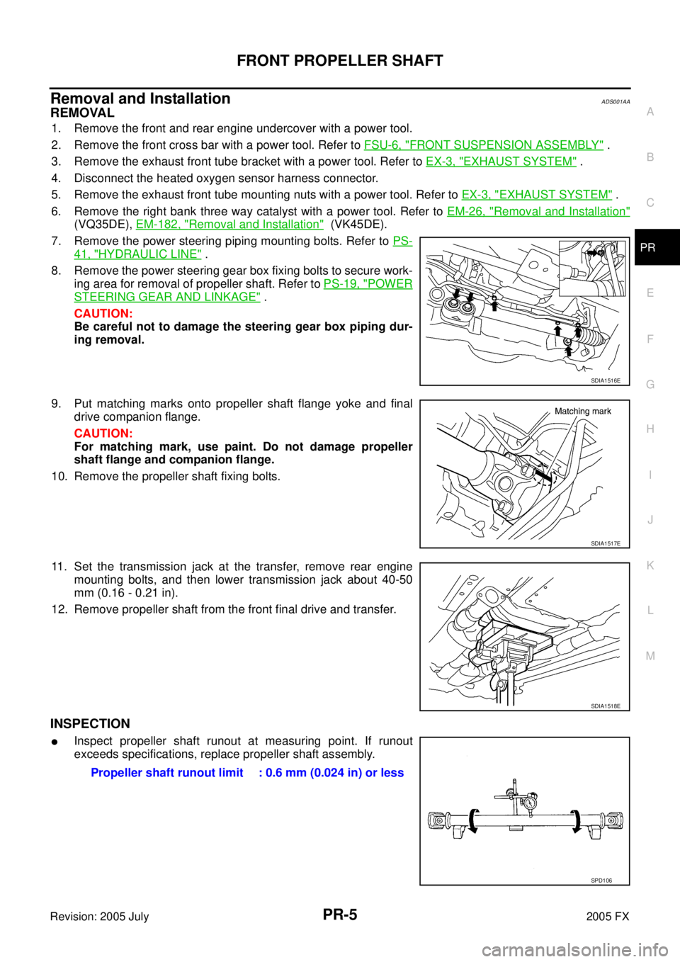
REMOVAL
1. Remove the front and rear engine undercover with a power tool.
2. Remove the front cross bar with a power tool. Refer to FSU-6, "
FRONT SUSPENSION ASSEMBLY" .
3. Remove the exhaust front tube bracket with a power tool. Refer to EX-3, "
EXHAUST SYSTEM" .
4. Disconnect the heated oxygen sensor harness connector.
5. Remove the exhaust front tube mounting nuts with a power tool. Refer to EX-3, "
EXHAUST SYSTEM" .
6. Remove the right bank three way catalyst with a power tool. Refer to EM-26, "
Removal and Installation"
(VQ35DE), EM-182, "Removal and Installation" (VK45DE).
7. Remove the power steering piping mounting bolts. Refer to PS-
41, "HYDRAULIC LINE" .
8. Remove the power steering gear box fixing bolts to secure work- ing area for removal of propeller shaft. Refer to PS-19, "
POWER
STEERING GEAR AND LINKAGE" .
CAUTION:
Be careful not to damage the steering gear box piping dur-
ing removal.
9. Put matching marks onto propeller shaft flange yoke and final drive companion flange.
CAUTION:
For matching mark, use paint. Do not damage propeller
shaft flange and companion flange.
10. Remove the propeller shaft fixing bolts.
11. Set the transmission jack at the transfer, remove rear engine mounting bolts, and then lower transmission jack about 40-50
mm (0.16 - 0.21 in).
12. Remove propeller shaft from the front final drive and transfer.
INSPECTION
�Inspect propeller shaft runout at measuring point. If runout
exceeds specifications, replace propeller shaft assembly.
SDIA1516E
SDIA1517E
SDIA1518E
Propeller shaft runout limit : 0.6 mm (0.024 in) or less
SPD106