Page 4308 of 4731

POWER STEERING OIL PUMP PS-33
C
D E
F
H I
J
K L
M A
B
PS
Revision: 2005 July 2005 FX
4. Remove piping of high pressure and low pressure (drain fluid from their pipings). Refer to PS-41,
"HYDRAULIC LINE" .
5. Remove mounting bolts, then remove power steering pump.
INSTALLATION
Refer to PS-41, "HYDRAULIC LINE" for tightening torque. Install in the reverse order removal.
�After installation, adjust belt tension. Refer to EM-15, "DRIVE BELTS" .
�After installation, bleed air. Refer to PS-8, "Air Bleeding Hydraulic System" .
Removal and Installation (VK45DE Models)AGS000HJ
REMOVAL
1. Remove undercover from vehicle with power tool.
2. Remove power steering oil pump belt from auto tensioner. Refer to EM-173, "
DRIVE BELTS" .
3. Drain power steering fluid from reservoir tank.
4. Remove piping of high pressure and low pressure from power steering oil pump (drain fluid from their pip- ings). Refer to PS-41, "
HYDRAULIC LINE" .
5. Remove mounting bolts, then remove power steering pump.
INSTALLATION
Refer to PS-41, "HYDRAULIC LINE" for tightening torque. Install in the reverse order removal.
After installation, bleed air. Refer to PS-8, "
Air Bleeding Hydraulic System" .
NOTE:
Adjustment of belt tension is no necessary because engine of this model equips auto tensioner.
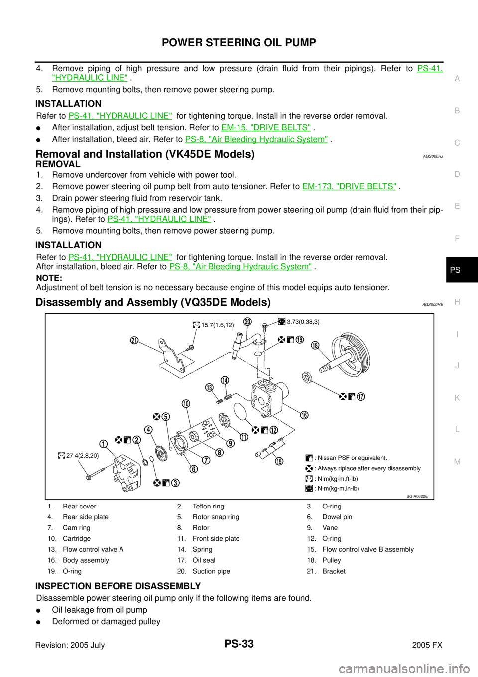
Disassembly and Assembly (VQ35DE Models)AGS000HE
INSPECTION BEFORE DISASSEMBLY
Disassemble power steering oil pump only if the following items are found.
�Oil leakage from oil pump
�Deformed or damaged pulley
1. Rear cover 2. Teflon ring 3. O-ring
4. Rear side plate 5. Rotor snap ring 6. Dowel pin
7. Cam ring 8. Rotor 9. Vane
10. Cartridge 11. Front side plate 12. O-ring
13. Flow control valve A 14. Spring 15. Flow control valve B assembly
16. Body assembly 17. Oil seal 18. Pulley
19. O-ring 20. Suction pipe 21. Bracket
SGIA0622E
Page 4316 of 4731
HYDRAULIC LINE PS-41
C
D E
F
H I
J
K L
M A
B
PS
Revision: 2005 July 2005 FX
HYDRAULIC LINEPFP:49721
ComponentsAGS000H5
VQ35DE 2WD MODEL
SGIA0559E
1. Reservoir tank 2. Reservoir tank bracket 3. Suction hose
4. High pressure hose 5. Oil pump 6. Steering gear assembly
Page 4317 of 4731
PS-42
HYDRAULIC LINE
Revision: 2005 July 2005 FX
VQ35DE AWD MODEL
7. Oil cooler 8. Eye bolt 9. Copper washer
10. Oil pressure sensor
SGIA0560E
1. Reservoir tank 2. Reservoir tank bracket 3. Suction hose
4. High pressure hose 5. Oil pump 6. Steering gear assembly
7. Oil cooler 8. Eye bolt 9. Copper washer
10. Oil pressure sensor
Page 4335 of 4731

RAX-12
REAR DRIVE SHAFT
Revision: 2005 July 2005 FX
ASSEMBLY
Final Drive Side
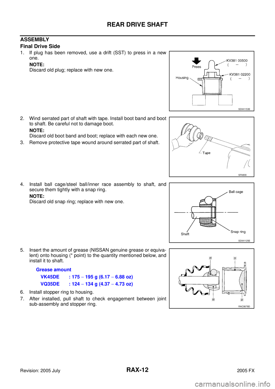
1. If plug has been removed, use a drift (SST) to press in a new one.
NOTE:
Discard old plug; replace with new one.
2. Wind serrated part of shaft with tape. Install boot band and boot to shaft. Be careful not to damage boot.
NOTE:
Discard old boot band and boot; replace with each new one.
3. Remove protective tape wound around serrated part of shaft.
4. Install ball cage/steel ball/inner race assembly to shaft, and secure them tightly with a snap ring.
NOTE:
Discard old snap ring; replace with new one.
5. Insert the amount of grease (NISSAN genuine grease or equiva- lent) onto housing (* point) to the quantity mentioned below, and
install it to shaft.
6. Install stopper ring to housing.
7. After installed, pull shaft to check engagement between joint sub-assembly and stopper ring.
SDIA1153E
SFA800
SDIA1125E
Grease amount
VK45DE : 175 − 195 g (6.17 − 6.88 oz)
VQ35DE : 124 − 134 g (4.37 − 4.73 oz)
RAC0678D
Page 4336 of 4731

REAR DRIVE SHAFT RAX-13
C E F
G H
I
J
K L
M A
B
RAX
Revision: 2005 July 2005 FX
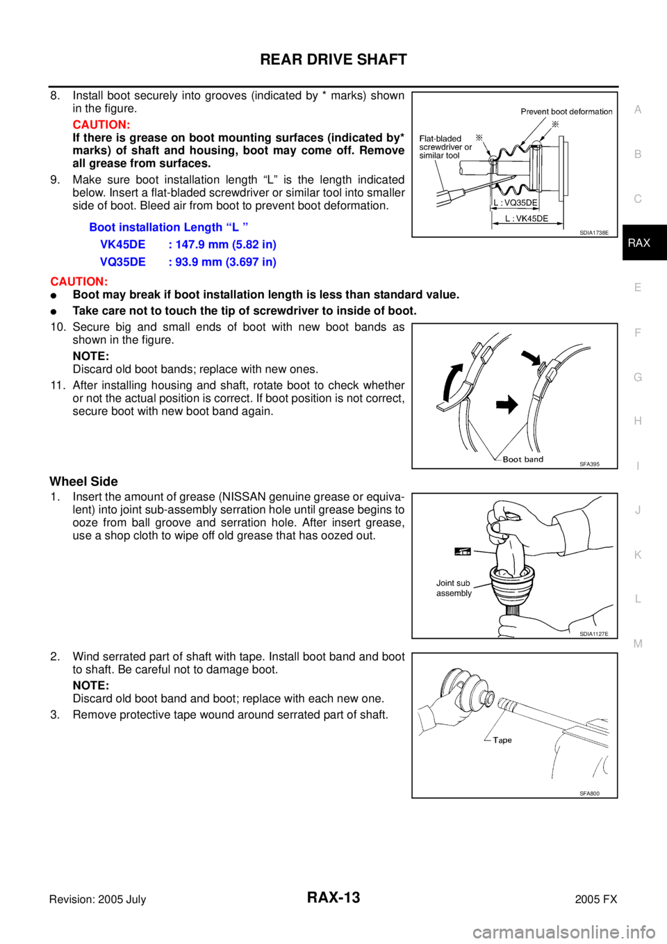
8. Install boot securely into grooves (indicated by * marks) shown
in the figure.
CAUTION:
If there is grease on boot mounting surfaces (indicated by*
marks) of shaft and housing, boot may come off. Remove
all grease from surfaces.
9. Make sure boot installation length “L” is the length indicated below. Insert a flat-bladed screwdriver or similar tool into smaller
side of boot. Bleed air from boot to prevent boot deformation.
CAUTION:
�Boot may break if boot installation length is less than standard value.
�Take care not to touch the tip of screwdriver to inside of boot.
10. Secure big and small ends of boot with new boot bands as shown in the figure.
NOTE:
Discard old boot bands; replace with new ones.
11. After installing housing and shaft, rotate boot to check whether or not the actual position is correct. If boot position is not correct,
secure boot with new boot band again.
Wheel Side
1. Insert the amount of grease (NISSAN genuine grease or equiva-
lent) into joint sub-assembly serration hole until grease begins to
ooze from ball groove and serration hole. After insert grease,
use a shop cloth to wipe off old grease that has oozed out.
2. Wind serrated part of shaft with tape. Install boot band and boot to shaft. Be careful not to damage boot.
NOTE:
Discard old boot band and boot; replace with each new one.
3. Remove protective tape wound around serrated part of shaft. Boot installation Length “L ”
VK45DE : 147.9 mm (5.82 in)
VQ35DE : 93.9 mm (3.697 in)
SDIA1738E
SFA395
SDIA1127E
SFA800
Page 4337 of 4731

RAX-14
REAR DRIVE SHAFT
Revision: 2005 July 2005 FX
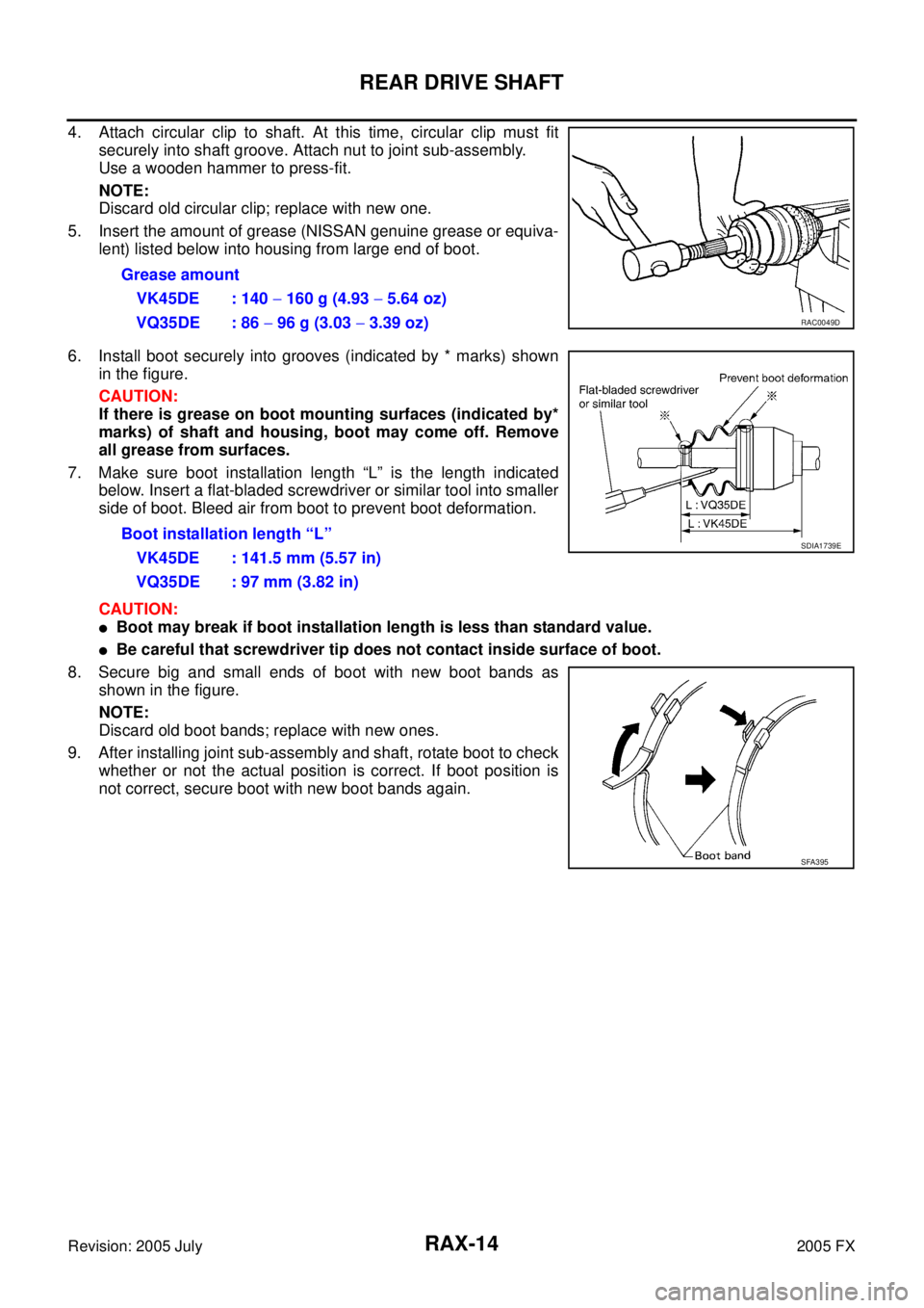
4. Attach circular clip to shaft. At this time, circular clip must fit
securely into shaft groove. Attach nut to joint sub-assembly.
Use a wooden hammer to press-fit.
NOTE:
Discard old circular clip; replace with new one.
5. Insert the amount of grease (NISSAN genuine grease or equiva- lent) listed below into housing from large end of boot.
6. Install boot securely into grooves (indicated by * marks) shown in the figure.
CAUTION:
If there is grease on boot mounting surfaces (indicated by*
marks) of shaft and housing, boot may come off. Remove
all grease from surfaces.
7. Make sure boot installation length “L” is the length indicated below. Insert a flat-bladed screwdriver or similar tool into smaller
side of boot. Bleed air from boot to prevent boot deformation.
CAUTION:
�Boot may break if boot installation length is less than standard value.
�Be careful that screwdriver tip does not contact inside surface of boot.
8. Secure big and small ends of boot with new boot bands as shown in the figure.
NOTE:
Discard old boot bands; replace with new ones.
9. After installing joint sub-assembly and shaft, rotate boot to check whether or not the actual position is correct. If boot position is
not correct, secure boot with new boot bands again. Grease amount
VK45DE : 140 − 160 g (4.93 − 5.64 oz)
VQ35DE : 86 − 96 g (3.03 − 3.39 oz)
RAC0049D
Boot installation length “L”
VK45DE : 141.5 mm (5.57 in)
VQ35DE : 97 mm (3.82 in) SDIA1739E
SFA395
Page 4338 of 4731
SERVICE DATA RAX-15
C E F
G H
I
J
K L
M A
B
RAX
Revision: 2005 July 2005 FX
SERVICE DATAPFP:00030
Wheel BearingADS000C9
Drive ShaftADS000KS
Axial end play0 mm (0 in)
Rotational torque At a load of 49,033 N (5,000 kg, 11,000 lb)
Less than 2.7 N·m (0.28 kg-m, 24 in-lb)
Measurement of spring scale Less than 26.6 N (2.7 kg, 5.95 lb)
Measuring point (Brake caliper installation points)
SDIA0801E
Joint Wheel side Final drive side
Engine model VQ35DE VK45DE VQ35DE VK45DE
Grease quantity 86
− 96 g
(3.03 − 3.39 oz) 140
− 160 g
(4.93 − 5.64 oz) 124
− 134 g
(4.37 − 4.73 oz) 175
− 195 g
(6.17 − 6.88 oz)
Boots installed length 97 mm (3.82 in) 141.5 mm (5.57 in) 93.9 mm (3.697 in) 147.9 mm (5.82 in)
Page 4372 of 4731
PREPARATION RFD-3
C E F
G H
I
J
K L
M A
B
RFD
Revision: 2005 July 2005 FX
PREPARATIONPFP:00002
Special Service ToolsADS001AG
The actual shapes of Kent-Moore tools may differ from those of special service tools illustrated here.
Tool number
(Kent-Moore No.)
Tool name Description
KV40104000
(—)
Flange wrench
a: 85 mm (3.35 in)
b: 65 mm (2.56 in) Removing and installing drive pinion lock nut
KV381054S0
(J-34286)
Puller Removing front oil seal
ST30720000
(J-25405)
Drift
a: 77 mm (3.03 in) dia.
b: 55.5 mm (2.185 in) dia.
�Installing front oil seal
�Installing pinion rear bearing outer race
KV40104100
(—)
Attachment Removing side flange (For VQ35DE models)
KV40101000
(—)
Attachment Removing side flange (For VK45DE models)
ST36230000
(J-25840-A)
Sliding hammer Removing side flange
KV38100200
(J-26233)
Drift
a: 65 mm (2.56 in) dia.
b: 49 mm (1.93 in) dia. Installing side oil seal
NT659
ZZA0601D
ZZA0811D
ZZA0804D
NT159
ZZA0803D
ZZA1143D