Page 4454 of 4731
STARTING SYSTEM SC-19
C
D E
F
G H
I
J
L
M A
B
SC
Revision: 2005 July 2005 FX
VQ35DE ENGINE MODELS (AWD)
Removal
1. Disconnect the battery cable from the negative terminal.
2. Remove engine front and rear undercover, using power tools.
3. Disconnect “S” connector.
4. Remove “B” terminal nut.
5. Remove starter motor mounting bolts.
6. Remove starter motor downward from the vehicle.
Installation
Installation is the reverse order of removal.
CAUTION:
Be sure to tighten “B” terminal nut carefully.
1. Starter motor mounting bolt 2. Oil pan 3. Starter motor
4. B terminal harness 5. B terminal nut 6. S connector
: N·m (kg-m, ft-lb) : Engine front
SKIB7207E
PKIA2844E
Page 4456 of 4731
STARTING SYSTEM SC-21
C
D E
F
G H
I
J
L
M A
B
SC
Revision: 2005 July 2005 FX
VQ35DE ENGINE MODELS (2WD)
1. Magnetic switch assembly 2. Dust cover kit 3. Shift lever set
4. Center bracket (A) 5. Yoke assembly 6. Armature assembly
7. Brush holder assembly 8. Thrust washer 9. Rear cover assembly
10. Shaft gear assembly 11. Packing 12. Thrust washer
13. Center bracket (P) 14. E-ring 15. Pinion assembly
16. Ball bearing 17. Caul 18. Gear case assembly
: N·m (kg-m, in-lb) (H): High-temperature grease point
PKIB8804E
Page 4457 of 4731
SC-22
STARTING SYSTEM
Revision: 2005 July 2005 FX
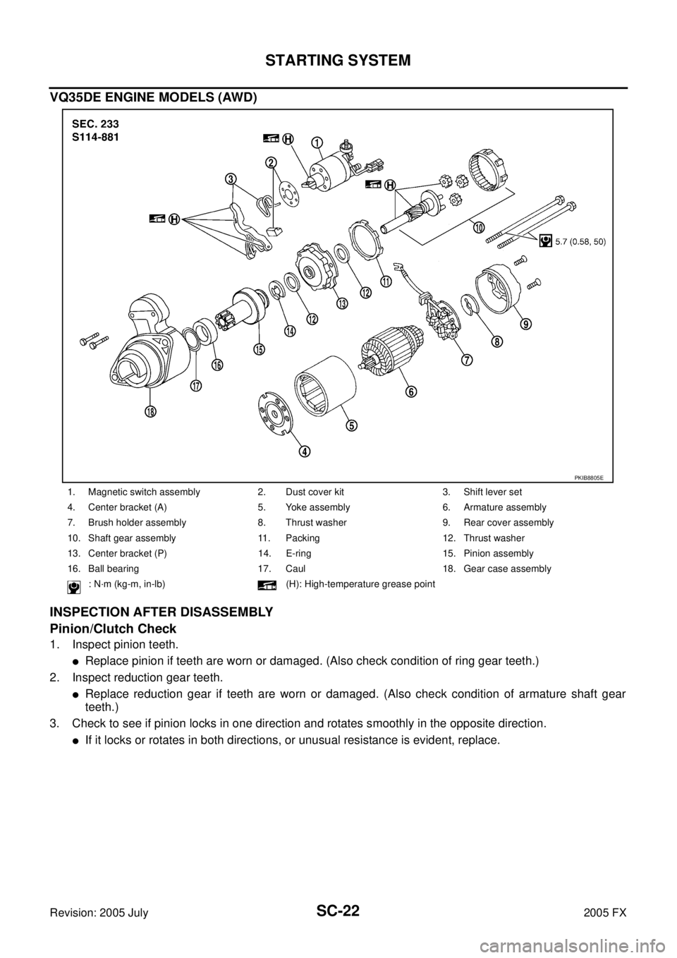
VQ35DE ENGINE MODELS (AWD)
INSPECTION AFTER DISASSEMBLY
Pinion/Clutch Check
1. Inspect pinion teeth.
�Replace pinion if teeth are worn or damaged. (Also check condition of ring gear teeth.)
2. Inspect reduction gear teeth.
�Replace reduction gear if teeth are worn or damaged. (Also check condition of armature shaft gear
teeth.)
3. Check to see if pinion locks in one direction and rotates smoothly in the opposite direction.
�If it locks or rotates in both directions, or unusual resistance is evident, replace.
1. Magnetic switch assembly 2. Dust cover kit 3. Shift lever set
4. Center bracket (A) 5. Yoke assembly 6. Armature assembly
7. Brush holder assembly 8. Thrust washer 9. Rear cover assembly
10. Shaft gear assembly 11. Packing 12. Thrust washer
13. Center bracket (P) 14. E-ring 15. Pinion assembly
16. Ball bearing 17. Caul 18. Gear case assembly
: N·m (kg-m, in-lb) (H): High-temperature grease point
PKIB8805E
Page 4458 of 4731

CHARGING SYSTEM SC-23
C
D E
F
G H
I
J
L
M A
B
SC
Revision: 2005 July 2005 FX
CHARGING SYSTEMPFP:23100
System DescriptionAKS0079I
The alternator provides DC voltage to operate the vehicle's electrical system and to keep the battery charged.
The voltage output is controlled by the IC regulator.
Power is supplied at all times
�through 10A fuse (No. 33, located in the fuse and fusible link block)
�to alternator terminal 4 (“S” terminal).
“B” Terminal supplies power to charge the battery and operate the vehicle's electrical system. Output voltage
is controlled by the IC regulator at terminal 4 (“S” terminal) detecting the input voltage.
The charging circuit is protected by the 120A fusible link (VK45DE and VQ35DE AWD).
The alternator is grounded to the engine block.
With the ignition switch in the ON or START position, power is supplied
�through 10A fuse [No. 14, located in the fuse block (J/B)]
�to combination meter terminal 7 for the charge warning lamp.
Ground is supplied
�to combination meter terminal 2
�through alternator terminal 3 (“L” terminal)
�to alternator terminal 2 (“E” terminal) (VK45DE) or through case ground (VQ35DE)
�through ground E304 (VK45DE).
With power and ground supplied, the charge warning lamp will illuminate. When the alternator is providing suf-
ficient voltage with the engine running, the ground is opened and the charge warning lamp will go off.
If the charge warning lamp illuminates with the engine running, a malfunction is indicated.
MALFUNCTION INDICATOR
The IC regulator warning function activates to illuminate charge warning lamp, if any of the following symp-
toms occur while alternator is operating:
�Excessive voltage is produced.
�No voltage is produced.
Page 4460 of 4731
CHARGING SYSTEM SC-25
C
D E
F
G H
I
J
L
M A
B
SC
Revision: 2005 July 2005 FX
VQ35DE ENGINE MODELS
TKWM0551E
Page 4463 of 4731
SC-28
CHARGING SYSTEM
Revision: 2005 July 2005 FX
WORK FLOW
*1SC-30, "Check “L” Terminal Circuit
(Open)"
*2SC-31, "Check “L” Terminal Circuit
(Short)"
*3SC-31, "Check “S” Terminal Circuit"
*4SC-32, "Check “B” Terminal Circuit"*5SC-34, "Alternator Pulley Inspec-
tion" (VK45DE)
SC-35, "
Alternator Pulley Inspec-
tion" (VQ35DE)
SKIB0527E
Page 4464 of 4731
CHARGING SYSTEM SC-29
C
D E
F
G H
I
J
L
M A
B
SC
Revision: 2005 July 2005 FX
PRELIMINARY INSPECTION
1. CHECK BATTERY TERMINALS CONNECTION
Check if battery terminals are clean and tight.
OK or NG
OK >> GO TO 2.
NG >> Repair battery terminals connection.
2. CHECK FUSE AND FUSIBLE LINK
Check for blown alternator and combination meter fuses.
OK or NG
OK >> GO TO 3.
NG >> If fuse is blown, be sure eliminate cause of malfunction before installing new fuse.
3. CHECK “E” TERMINAL CONNECTION
Check if “E” terminal is clean and tight.
OK or NG
OK >> GO TO 4.
NG >> Repair “E” terminal connection.
4. CHECK ALTERNATOR DRIVE BELT TENSION
Check alternator drive belt tension. Refer to EM-173, "
Checking Drive Belts" (VK45DE) or EM-15, "Checking
Drive Belts" (VQ35DE).
OK or NG
OK >> INSPECTION END
NG >> Repair as needed.
Unit Power source (Power supply terminals) Fuse No.
Alternator Battery (“S” terminal) 33
Combination meter Ignition switch ON (“L” terminal) 14
Page 4465 of 4731
SC-30
CHARGING SYSTEM
Revision: 2005 July 2005 FX
DIAGNOSTIC PROCEDURE 1
Check “L” Terminal Circuit (Open)
1. CHECK “L” TERMINAL CONNECTION
1. Turn ignition switch OFF.
2. Check if “L” terminal is clean and tight.
OK or NG
OK >> GO TO 2.
NG >> Repair “L” terminal connection. Confirm repair by performing complete Battery/Starting/Charging system test.
2. CHECK “L” TERMINAL CIRCUIT (OPEN)
1. Disconnect alternator connector.
2. Apply ground to alternator harness connector E311 (VK45DE) or F26 (VQ35DE) terminal 3 (OR) with the ignition switch in the ON
position.
OK or NG
OK >> Go to SC-28, "WORK FLOW" .
NG >> Check the following.
�Charge warning lamp (combination meter)
�Harness for open between combination meter and fuse
�Harness for open between combination meter and alternator
3 (OR) – Ground : Charge warning lamp should
light up.
SKIB0599E

Removal
1. Disconnect the battery cable from the negative terminal.
2. Remove eng")

1. Magnetic switch assembly 2. Dust cover kit 3. Shift lever set
4. Center bracket")

\"
*2SC-31, \"Check “L” Terminal Circuit
(Short)\"
*3SC-31, \"Check “S” Terminal Circui")


1. CHECK “L” TERMINAL CONNECTION
1. Turn ignition switch OFF.
2. Check if “L”")