2005 CHRYSLER CARAVAN belt
[x] Cancel search: beltPage 1331 of 2339
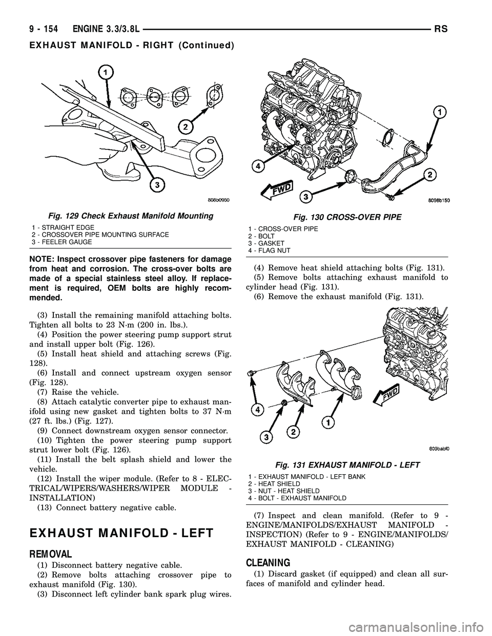
NOTE: Inspect crossover pipe fasteners for damage
from heat and corrosion. The cross-over bolts are
made of a special stainless steel alloy. If replace-
ment is required, OEM bolts are highly recom-
mended.
(3) Install the remaining manifold attaching bolts.
Tighten all bolts to 23 N´m (200 in. lbs.).
(4) Position the power steering pump support strut
and install upper bolt (Fig. 126).
(5) Install heat shield and attaching screws (Fig.
128).
(6) Install and connect upstream oxygen sensor
(Fig. 128).
(7) Raise the vehicle.
(8) Attach catalytic converter pipe to exhaust man-
ifold using new gasket and tighten bolts to 37 N´m
(27 ft. lbs.) (Fig. 127).
(9) Connect downstream oxygen sensor connector.
(10) Tighten the power steering pump support
strut lower bolt (Fig. 126).
(11) Install the belt splash shield and lower the
vehicle.
(12) Install the wiper module. (Refer to 8 - ELEC-
TRICAL/WIPERS/WASHERS/WIPER MODULE -
INSTALLATION)
(13) Connect battery negative cable.
EXHAUST MANIFOLD - LEFT
REMOVAL
(1) Disconnect battery negative cable.
(2) Remove bolts attaching crossover pipe to
exhaust manifold (Fig. 130).
(3) Disconnect left cylinder bank spark plug wires.(4) Remove heat shield attaching bolts (Fig. 131).
(5) Remove bolts attaching exhaust manifold to
cylinder head (Fig. 131).
(6) Remove the exhaust manifold (Fig. 131).
(7) Inspect and clean manifold. (Refer to 9 -
ENGINE/MANIFOLDS/EXHAUST MANIFOLD -
INSPECTION) (Refer to 9 - ENGINE/MANIFOLDS/
EXHAUST MANIFOLD - CLEANING)CLEANING
(1) Discard gasket (if equipped) and clean all sur-
faces of manifold and cylinder head.
Fig. 129 Check Exhaust Manifold Mounting
1 - STRAIGHT EDGE
2 - CROSSOVER PIPE MOUNTING SURFACE
3 - FEELER GAUGE
Fig. 130 CROSS-OVER PIPE
1 - CROSS-OVER PIPE
2 - BOLT
3 - GASKET
4 - FLAG NUT
Fig. 131 EXHAUST MANIFOLD - LEFT
1 - EXHAUST MANIFOLD - LEFT BANK
2 - HEAT SHIELD
3 - NUT - HEAT SHIELD
4 - BOLT - EXHAUST MANIFOLD
9 - 154 ENGINE 3.3/3.8LRS
EXHAUST MANIFOLD - RIGHT (Continued)
Page 1333 of 2339
(4) Apply force in the reverse direction to the fol-
lowing torque:
²41 N´m (30 ft. lb.) with cylinder heads installed
²20 N´m (15 ft. lb.) with cylinder heads removed
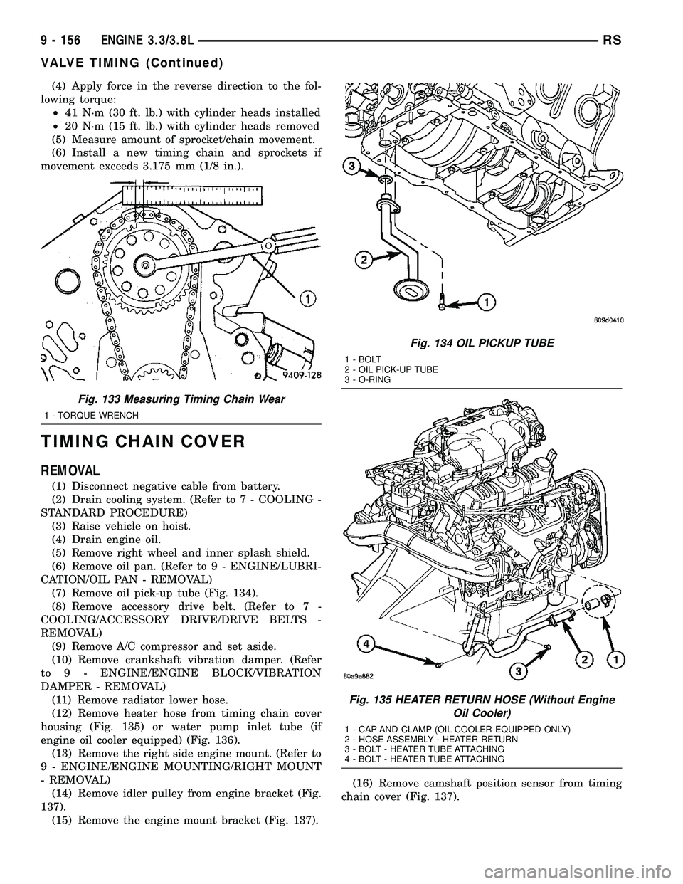
(5) Measure amount of sprocket/chain movement.
(6) Install a new timing chain and sprockets if
movement exceeds 3.175 mm (1/8 in.).
TIMING CHAIN COVER
REMOVAL
(1) Disconnect negative cable from battery.
(2) Drain cooling system. (Refer to 7 - COOLING -
STANDARD PROCEDURE)
(3) Raise vehicle on hoist.
(4) Drain engine oil.
(5) Remove right wheel and inner splash shield.
(6) Remove oil pan. (Refer to 9 - ENGINE/LUBRI-
CATION/OIL PAN - REMOVAL)
(7) Remove oil pick-up tube (Fig. 134).
(8) Remove accessory drive belt. (Refer to 7 -
COOLING/ACCESSORY DRIVE/DRIVE BELTS -
REMOVAL)
(9) Remove A/C compressor and set aside.
(10) Remove crankshaft vibration damper. (Refer
to 9 - ENGINE/ENGINE BLOCK/VIBRATION
DAMPER - REMOVAL)
(11) Remove radiator lower hose.
(12) Remove heater hose from timing chain cover
housing (Fig. 135) or water pump inlet tube (if
engine oil cooler equipped) (Fig. 136).
(13) Remove the right side engine mount. (Refer to
9 - ENGINE/ENGINE MOUNTING/RIGHT MOUNT
- REMOVAL)
(14) Remove idler pulley from engine bracket (Fig.
137).
(15) Remove the engine mount bracket (Fig. 137).(16) Remove camshaft position sensor from timing
chain cover (Fig. 137).
Fig. 133 Measuring Timing Chain Wear
1 - TORQUE WRENCH
Fig. 134 OIL PICKUP TUBE
1 - BOLT
2 - OIL PICK-UP TUBE
3 - O-RING
Fig. 135 HEATER RETURN HOSE (Without Engine
Oil Cooler)
1 - CAP AND CLAMP (OIL COOLER EQUIPPED ONLY)
2 - HOSE ASSEMBLY - HEATER RETURN
3 - BOLT - HEATER TUBE ATTACHING
4 - BOLT - HEATER TUBE ATTACHING
9 - 156 ENGINE 3.3/3.8LRS
VALVE TIMING (Continued)
Page 1336 of 2339
(17) Install accessory drive belt. (Refer to 7 -
COOLING/ACCESSORY DRIVE/DRIVE BELTS -
INSTALLATION)
(18) Install oil pump pick-up tube with new
O-ring. Tighten attaching bolt to 28 N´m (250 in.
lbs.).
(19) Install oil pan. (Refer to 9 - ENGINE/LUBRI-
CATION/OIL PAN - INSTALLATION)
(20) Install inner splash shield and right front
wheel.
(21) Fill crankcase with engine oil to proper level.
(22) Fill cooling system. (Refer to 7 - COOLING -
STANDARD PROCEDURE)
(23) Connect negative cable to battery.
TIMING CHAIN AND
SPROCKETS
REMOVAL
REMOVAL - TIMING CHAIN AND CAMSHAFT
SPROCKET
(1) Disconnect negative cable from battery.
(2) Remove the timing chain cover. (Refer to 9 -
ENGINE/VALVE TIMING/TIMING BELT / CHAIN
COVER(S) - REMOVAL)
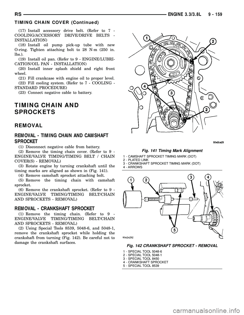
(3) Rotate engine by turning crankshaft until the
timing marks are aligned as shown in (Fig. 141).
(4) Remove camshaft sprocket attaching bolt.
(5) Remove the timing chain with camshaft
sprocket.
(6) Remove the crankshaft sprocket. (Refer to 9 -
ENGINE/VALVE TIMING/TIMING BELT/CHAIN
AND SPROCKETS - REMOVAL)
REMOVAL - CRANKSHAFT SPROCKET
(1) Remove the timing chain. (Refer to 9 -
ENGINE/VALVE TIMING/TIMING BELT/CHAIN
AND SPROCKETS - REMOVAL)
(2) Using Special Tools 8539, 5048-6, and 5048-1,
remove the crankshaft sprocket while holding the
crankshaft from turning (Fig. 142). Be careful not to
damage the crankshaft surfaces.
Fig. 141 Timing Mark Alignment
1 - CAMSHAFT SPROCKET TIMING MARK (DOT)
2 - PLATED LINK
3 - CRANKSHAFT SPROCKET TIMING MARK (DOT)
4 - ARROWS
Fig. 142 CRANKSHAFT SPROCKET - REMOVAL
1 - SPECIAL TOOL 5048-6
2 - SPECIAL TOOL 5048-1
3 - SPECIAL TOOL 8450
4 - CRANKSHAFT SPROCKET
5 - SPECIAL TOOL 8539
RSENGINE 3.3/3.8L9 - 159
TIMING CHAIN COVER (Continued)
Page 1337 of 2339
INSTALLATION
INSTALLATION - CRANKSHAFT SPROCKET
(1) Position the sprocket on the crankshaft (timing
mark out) with the timing slot aligned with the tim-
ing pin.
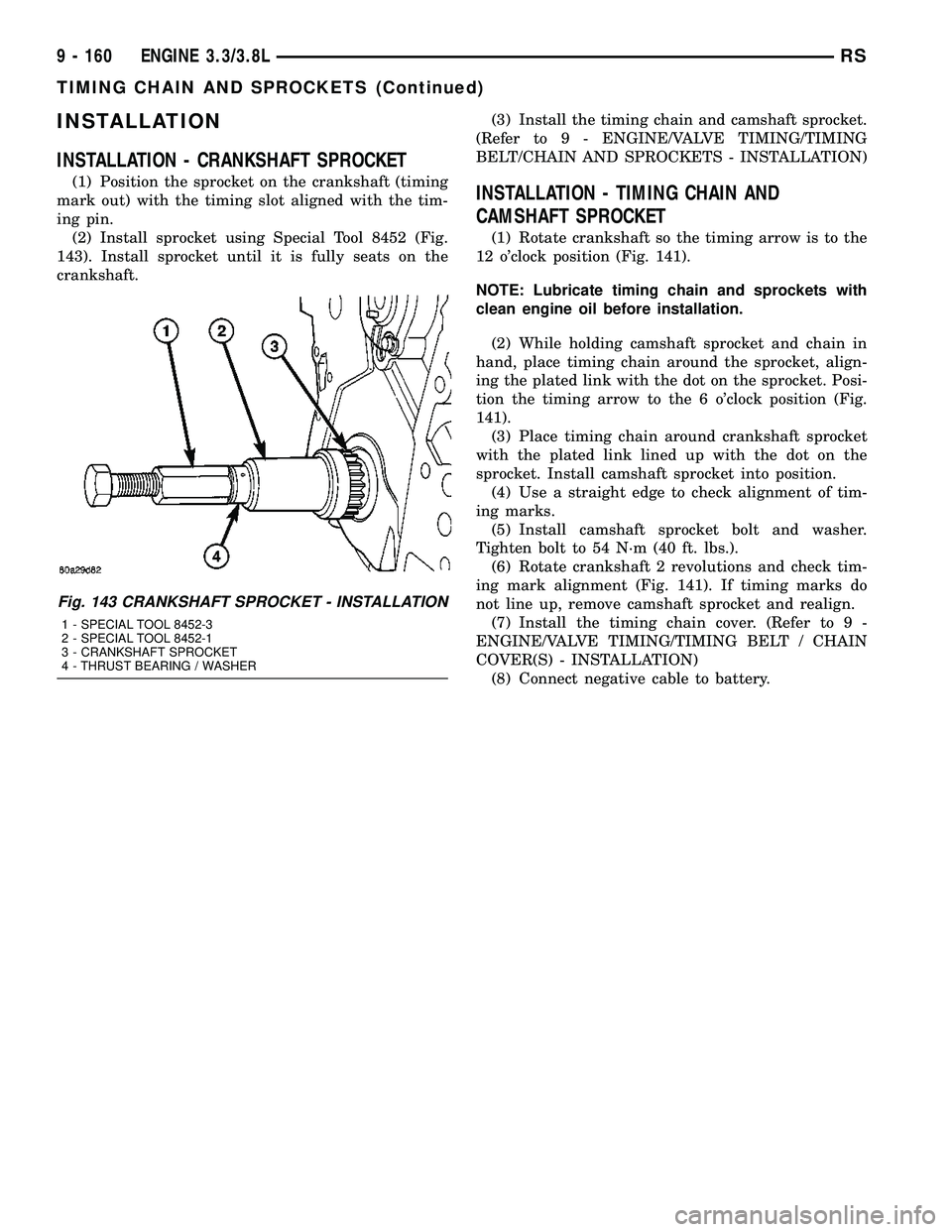
(2) Install sprocket using Special Tool 8452 (Fig.
143). Install sprocket until it is fully seats on the
crankshaft.(3) Install the timing chain and camshaft sprocket.
(Refer to 9 - ENGINE/VALVE TIMING/TIMING
BELT/CHAIN AND SPROCKETS - INSTALLATION)INSTALLATION - TIMING CHAIN AND
CAMSHAFT SPROCKET
(1) Rotate crankshaft so the timing arrow is to the
12 o'clock position (Fig. 141).
NOTE: Lubricate timing chain and sprockets with
clean engine oil before installation.
(2) While holding camshaft sprocket and chain in
hand, place timing chain around the sprocket, align-
ing the plated link with the dot on the sprocket. Posi-
tion the timing arrow to the 6 o'clock position (Fig.
141).
(3) Place timing chain around crankshaft sprocket
with the plated link lined up with the dot on the
sprocket. Install camshaft sprocket into position.
(4) Use a straight edge to check alignment of tim-
ing marks.
(5) Install camshaft sprocket bolt and washer.
Tighten bolt to 54 N´m (40 ft. lbs.).
(6) Rotate crankshaft 2 revolutions and check tim-
ing mark alignment (Fig. 141). If timing marks do
not line up, remove camshaft sprocket and realign.
(7) Install the timing chain cover. (Refer to 9 -
ENGINE/VALVE TIMING/TIMING BELT / CHAIN
COVER(S) - INSTALLATION)
(8) Connect negative cable to battery.
Fig. 143 CRANKSHAFT SPROCKET - INSTALLATION
1 - SPECIAL TOOL 8452-3
2 - SPECIAL TOOL 8452-1
3 - CRANKSHAFT SPROCKET
4 - THRUST BEARING / WASHER
9 - 160 ENGINE 3.3/3.8LRS
TIMING CHAIN AND SPROCKETS (Continued)
Page 1394 of 2339
CRANKSHAFT POSITION
SENSOR
DESCRIPTION
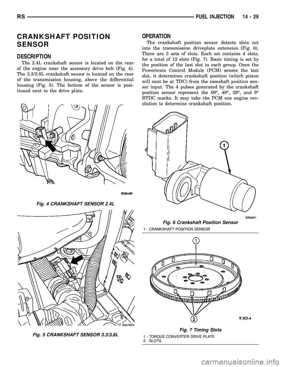
The 2.4L crankshaft sensor is located on the rear
of the engine near the accessory drive belt (Fig. 4).
The 3.3/3.8L crankshaft sensor is located on the rear
of the transmission housing, above the differential
housing (Fig. 5). The bottom of the sensor is posi-
tioned next to the drive plate.
OPERATION
The crankshaft position sensor detects slots cut
into the transmission driveplate extension (Fig. 6).
There are 3 sets of slots. Each set contains 4 slots,
for a total of 12 slots (Fig. 7). Basic timing is set by
the position of the last slot in each group. Once the
Powertrain Control Module (PCM) senses the last
slot, it determines crankshaft position (which piston
will next be at TDC) from the camshaft position sen-
sor input. The 4 pulses generated by the crankshaft
position sensor represent the 69É, 49É, 29É, and 9É
BTDC marks. It may take the PCM one engine rev-
olution to determine crankshaft position.
Fig. 4 CRANKSHAFT SENSOR 2.4L
Fig. 5 CRANKSHAFT SENSOR 3.3/3.8L
Fig. 6 Crankshaft Position Sensor
1 - CRANKSHAFT POSITION SENSOR
Fig. 7 Timing Slots
1 - TORQUE CONVERTER DRIVE PLATE
2 - SLOTS
RSFUEL INJECTION14-29
Page 1408 of 2339
STEERING
TABLE OF CONTENTS
page page
STEERING
DESCRIPTION - POWER STEERING SYSTEM . . 1
OPERATION - POWER STEERING SYSTEM . . . 1
DIAGNOSIS AND TESTING
DIAGNOSIS AND TESTING - POWER
STEERING SYSTEM FLOW AND
PRESSURE TEST......................1
DIAGNOSIS AND TESTING - STEERING
SYSTEM DIAGNOSIS CHARTS............3SPECIFICATIONS
POWER STEERING FASTENER TORQUE . . . 9
SPECIAL TOOLS
POWER STEERING....................9
COLUMN..............................10
GEAR.................................26
PUMP.................................36
STEERING
DESCRIPTION - POWER STEERING SYSTEM
This vehicle comes with power steering as stan-
dard equipment. The power steering system consists
of these major components:
²POWER STEERING PUMP
²POWER STEERING GEAR
²POWER STEERING FLUID
²POWER STEERING FLUID COOLER (If
Equipped)
²POWER STEERING FLUID RESERVOIR
²POWER STEERING FLUID SUPPLY HOSE
²POWER STEERING FLUID PRESSURE HOSE
²POWER STEERING FLUID RETURN HOSE
For information on the first two components, refer
to their respective sections within this service man-
ual group. Information on all other components can
be found in POWER STEERING PUMP.
OPERATION - POWER STEERING SYSTEM
Turning of the steering wheel is converted into lin-
ear (side-to-side) travel through the meshing of the
helical pinion teeth with the rack teeth within the
steering gear. The lateral travel pushes and pulls the
tie rods to change the direction of the vehicle's front
wheels.
Power assist steering is provided by a belt driven
rotary type pump. It directs fluid through power
steering fluid hoses to the power steering gear where
it is used to assist the driver's turning effort.
Manual steering control of the vehicle can be main-
tained if power steering assist is lost. However,
under this condition, steering effort is significantly
increased.
DIAGNOSIS AND TESTING
DIAGNOSIS AND TESTING - POWER STEERING
SYSTEM FLOW AND PRESSURE TEST
ALL ENGINES
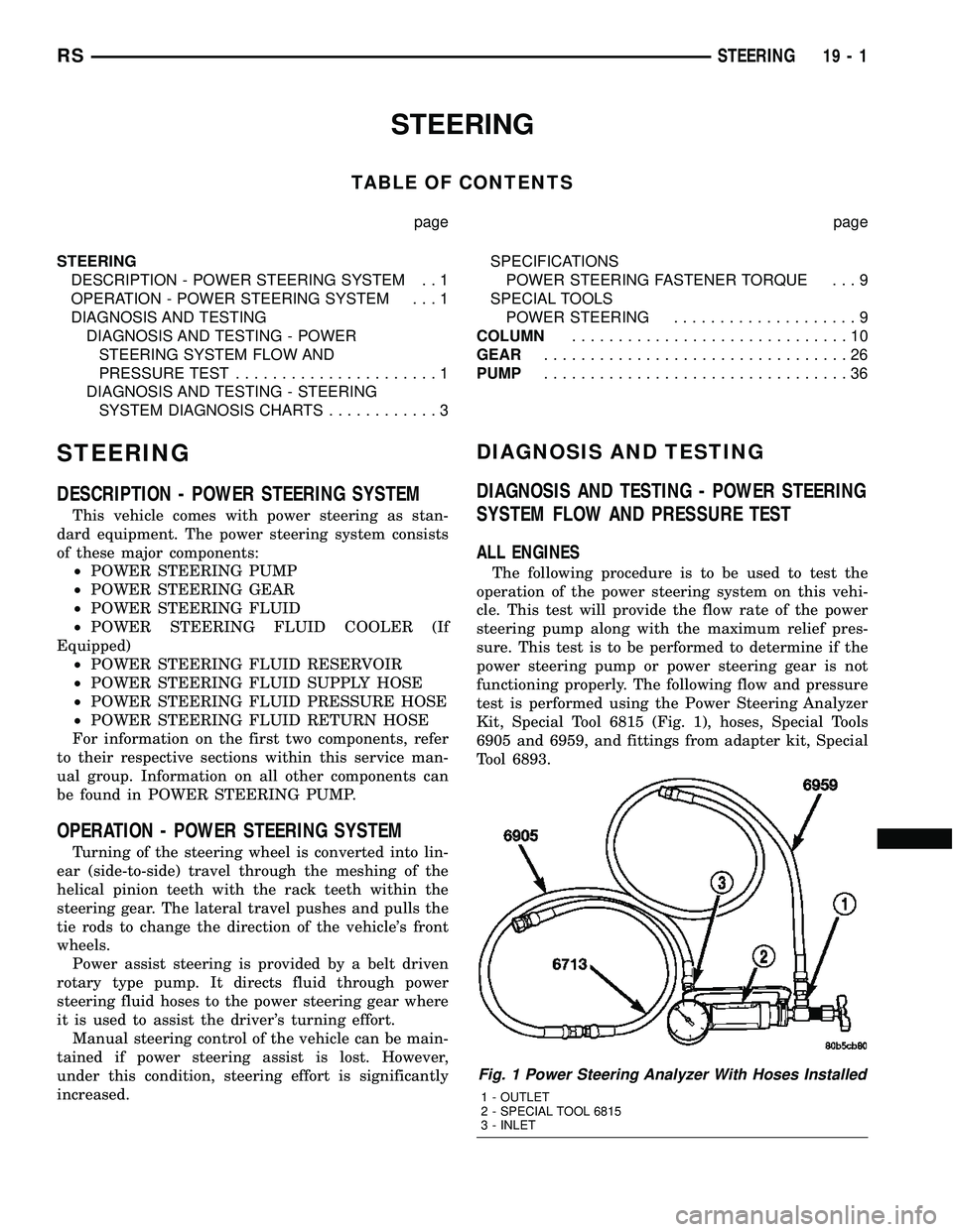
The following procedure is to be used to test the
operation of the power steering system on this vehi-
cle. This test will provide the flow rate of the power
steering pump along with the maximum relief pres-
sure. This test is to be performed to determine if the
power steering pump or power steering gear is not
functioning properly. The following flow and pressure
test is performed using the Power Steering Analyzer
Kit, Special Tool 6815 (Fig. 1), hoses, Special Tools
6905 and 6959, and fittings from adapter kit, Special
Tool 6893.
Fig. 1 Power Steering Analyzer With Hoses Installed
1 - OUTLET
2 - SPECIAL TOOL 6815
3 - INLET
RSSTEERING19-1
Page 1409 of 2339
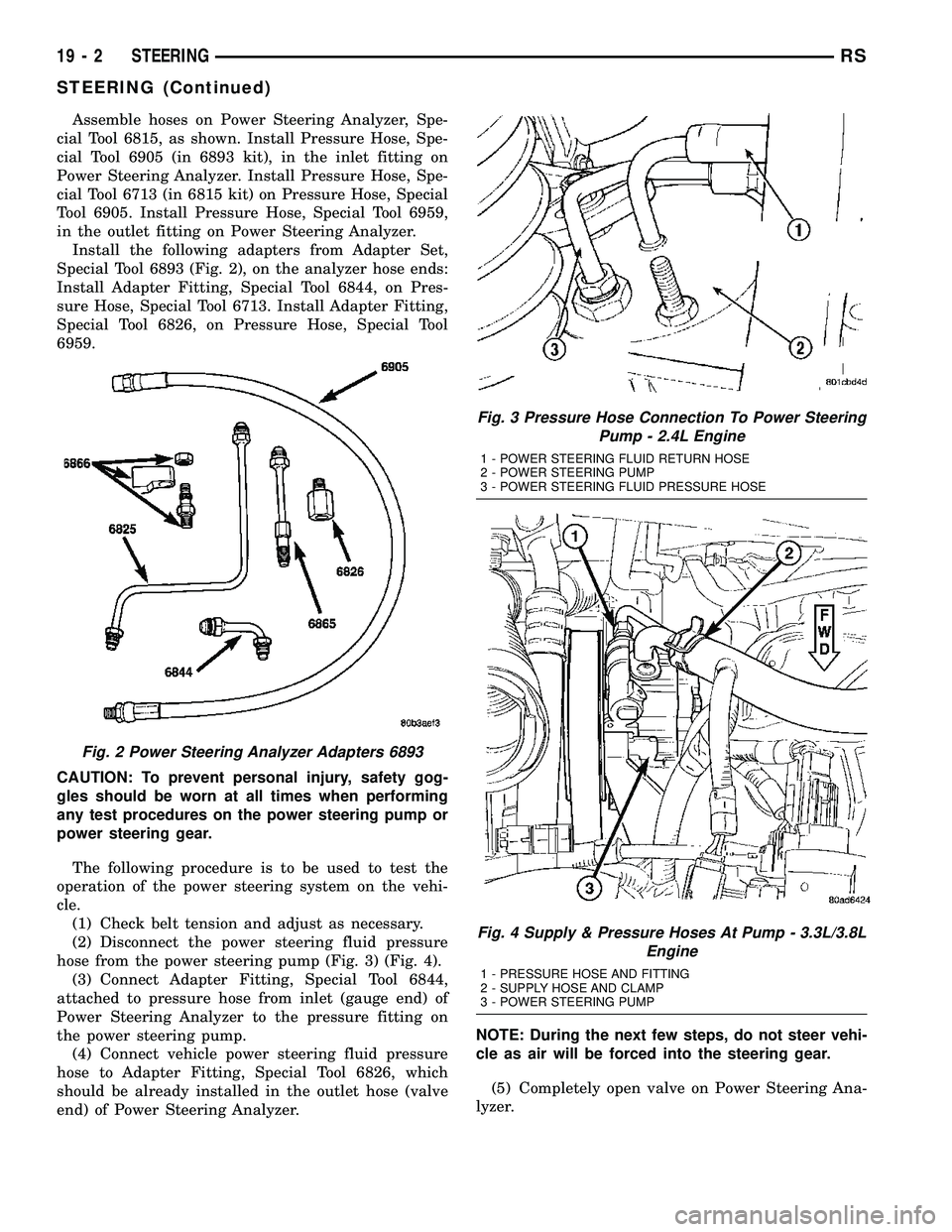
Assemble hoses on Power Steering Analyzer, Spe-
cial Tool 6815, as shown. Install Pressure Hose, Spe-
cial Tool 6905 (in 6893 kit), in the inlet fitting on
Power Steering Analyzer. Install Pressure Hose, Spe-
cial Tool 6713 (in 6815 kit) on Pressure Hose, Special
Tool 6905. Install Pressure Hose, Special Tool 6959,
in the outlet fitting on Power Steering Analyzer.
Install the following adapters from Adapter Set,
Special Tool 6893 (Fig. 2), on the analyzer hose ends:
Install Adapter Fitting, Special Tool 6844, on Pres-
sure Hose, Special Tool 6713. Install Adapter Fitting,
Special Tool 6826, on Pressure Hose, Special Tool
6959.
CAUTION: To prevent personal injury, safety gog-
gles should be worn at all times when performing
any test procedures on the power steering pump or
power steering gear.
The following procedure is to be used to test the
operation of the power steering system on the vehi-
cle.
(1) Check belt tension and adjust as necessary.
(2) Disconnect the power steering fluid pressure
hose from the power steering pump (Fig. 3) (Fig. 4).
(3) Connect Adapter Fitting, Special Tool 6844,
attached to pressure hose from inlet (gauge end) of
Power Steering Analyzer to the pressure fitting on
the power steering pump.
(4) Connect vehicle power steering fluid pressure
hose to Adapter Fitting, Special Tool 6826, which
should be already installed in the outlet hose (valve
end) of Power Steering Analyzer.NOTE: During the next few steps, do not steer vehi-
cle as air will be forced into the steering gear.
(5) Completely open valve on Power Steering Ana-
lyzer.
Fig. 2 Power Steering Analyzer Adapters 6893
Fig. 3 Pressure Hose Connection To Power Steering
Pump - 2.4L Engine
1 - POWER STEERING FLUID RETURN HOSE
2 - POWER STEERING PUMP
3 - POWER STEERING FLUID PRESSURE HOSE
Fig. 4 Supply & Pressure Hoses At Pump - 3.3L/3.8L
Engine
1 - PRESSURE HOSE AND FITTING
2 - SUPPLY HOSE AND CLAMP
3 - POWER STEERING PUMP
19 - 2 STEERINGRS
STEERING (Continued)
Page 1411 of 2339
CONDITION POSSIBLE CAUSES CORRECTION
4. Loose lower control arm mounting
bolts at front suspension
crossmember.4. Tighten control arm mounting bolts to
the specified torques.
5. Lower control arm pivot bushing
worn.5. Replace lower control arm pivot
bushing.
6. Loose strut assembly mounting
fasteners at tower or knuckle.6. Tighten strut assembly fasteners to
the specified torque.
7. Power steering fluid hose touching
the body of the vehicle.7. Adjust hose to proper position by
loosening, repositioning, and tightening
attachments to specified torque. Do not
bend tubing.
8. Damaged front suspension
crossmember.8. Replace front suspension
crossmember.
9. Stabilizer bar link ball joints worn. 9. Replace stabilizer bar link.
10. Lug nuts loose. 10. Tighten lug nuts to specifications.
11. Excessive Wheel bearing
free-play.11. Verify correct halfshaft hub nut
torque. Replace hub and bearing if
torque is okay.
12. Internal power steering gear
noise.12. Replace power steering gear.
POPPING NOISE 1. Worn outer tie rod. 1. Check ball joint for free-play;
Replace outer tie rod.
2. Loose inner tie rod. 2. Replace power steering gear.
CHIRP OR SQUEAL
(POWER STEERING
PUMP)1. Loose power steering pump drive
belt.1. Check and adjust power steering
pump drive belt to specifications or
replace automatic tensioner where
applicable. Replace belt if worn or
glazed.
2. Malfuctioning belt auto-tensioner 2. Replace belt auto-tensioner.
WHINE, GROWL, MOAN
OR GROAN (POWER
STEERING PUMP)***1. Low fluid level. 1. Fill power steering fluid reservoir to
proper level and check for leaks (make
sure all air is bled from the system
fluid).
2. Power steering hose touching
vehicle body or frame.2. Adjust hose to proper position by
loosening, repositioning, and tightening
fitting to specified torque. Do not bend
tubing. Replace hose if damaged.
3. Extremely low ambient
temperature.3. Some noise can be expected, but will
go away as vehicle warms. Replace
pump if noise is excessive.
4. Extreme wear of power steering
pump internal components.4. Replace power steering pump and
flush system as necessary.
19 - 4 STEERINGRS
STEERING (Continued)