2005 CHRYSLER CARAVAN belt
[x] Cancel search: beltPage 1801 of 2339
(7) Disengage clip holding door lock linkage to
door latch.
(8) Remove lock linkage from latch.
(9) Remove nuts holding outside door handle to
door outer panel.
(10) Remove outside door handle from vehicle.
INSTALLATION
If outside door handle replacement is necessary,
transfer lock cylinder from the original handle to the
new one.
(1) Place outside door handle in position on vehi-
cle.
(2) Install nuts attaching outside door handle to
door outer panel (Fig. 11). Tighten nuts to 6 N´m (50
in. lbs.).
(3) Insert lock linkage into door latch.
(4) Engage clip to hold door lock linkage to latch.
(5) Insert latch linkage into door latch.
(6) Engage clip to hold door latch linkage to latch.
(7) Install push-in fasteners to hold VTSS switch
harness to inner door reinforcement bar, if equipped.
(8) Connect VTSS switch connector into door har-
ness, if equipped.
(9) Verify door latch operation.
(10) Install sound shield and door trim panel.
WINDOW REGULATOR -
POWER
REMOVAL
(1) Remove watershield. (Refer to 23 - BODY/
DOOR - FRONT/WATERSHIELD - REMOVAL)
(2) Remove inner belt molding.(Refer to 23 -
BODY/WEATHERSTRIP/SEALS/FDR INNER BELT
WEATHERSTRIP - REMOVAL)
(3) Remove door glass. (Refer to 23 - BODY/DOOR
- FRONT/DOOR GLASS - REMOVAL).
(4) Disconnect wire connector from power window
motor.
(5) Loosen screws attaching front and rear window
guide rails to inner door panel.
(6) Remove screw heads on guide rails from key
hole slots in inner door panel.
(7) Loosen screws attaching motor/housing to inner
door panel.
(8) Remove regulator from inner door panel.
(9) Extract rear guide rail through inner door
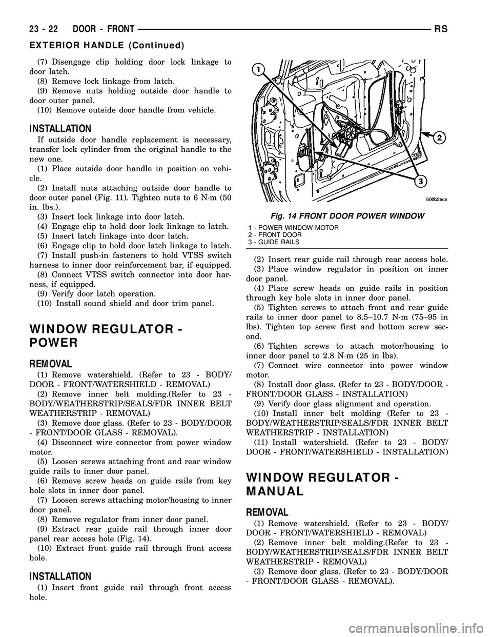
panel rear access hole (Fig. 14).
(10) Extract front guide rail through front access
hole.
INSTALLATION
(1) Insert front guide rail through front access
hole.(2) Insert rear guide rail through rear access hole.
(3) Place window regulator in position on inner
door panel.
(4) Place screw heads on guide rails in position
through key hole slots in inner door panel.
(5) Tighten screws to attach front and rear guide
rails to inner door panel to 8.5±10.7 N´m (75±95 in
lbs). Tighten top screw first and bottom screw sec-
ond.
(6) Tighten screws to attach motor/housing to
inner door panel to 2.8 N´m (25 in lbs).
(7) Connect wire connector into power window
motor.
(8) Install door glass. (Refer to 23 - BODY/DOOR -
FRONT/DOOR GLASS - INSTALLATION)
(9) Verify door glass alignment and operation.
(10) Install inner belt molding (Refer to 23 -
BODY/WEATHERSTRIP/SEALS/FDR INNER BELT
WEATHERSTRIP - INSTALLATION)
(11) Install watershield. (Refer to 23 - BODY/
DOOR - FRONT/WATERSHIELD - INSTALLATION)
WINDOW REGULATOR -
MANUAL
REMOVAL
(1) Remove watershield. (Refer to 23 - BODY/
DOOR - FRONT/WATERSHIELD - REMOVAL)
(2) Remove inner belt molding.(Refer to 23 -
BODY/WEATHERSTRIP/SEALS/FDR INNER BELT
WEATHERSTRIP - REMOVAL)
(3) Remove door glass. (Refer to 23 - BODY/DOOR
- FRONT/DOOR GLASS - REMOVAL).
Fig. 14 FRONT DOOR POWER WINDOW
1 - POWER WINDOW MOTOR
2 - FRONT DOOR
3 - GUIDE RAILS
23 - 22 DOOR - FRONTRS
EXTERIOR HANDLE (Continued)
Page 1802 of 2339
(4) Loosen screws attaching front and rear window
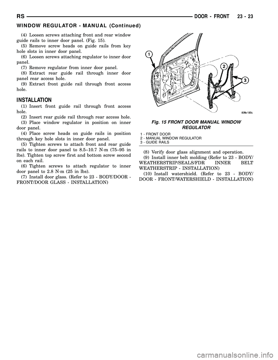
guide rails to inner door panel. (Fig. 15).
(5) Remove screw heads on guide rails from key
hole slots in inner door panel.
(6) Loosen screws attaching regulator to inner door
panel.
(7) Remove regulator from inner door panel.
(8) Extract rear guide rail through inner door
panel rear access hole.
(9) Extract front guide rail through front access
hole.
INSTALLATION
(1) Insert front guide rail through front access
hole.
(2) Insert rear guide rail through rear access hole.
(3) Place window regulator in position on inner
door panel.
(4) Place screw heads on guide rails in position
through key hole slots in inner door panel.
(5) Tighten screws to attach front and rear guide
rails to inner door panel to 8.5±10.7 N´m (75±95 in
lbs). Tighten top screw first and bottom screw second
on each rail.
(6) Tighten screws to attach regulator to inner
door panel to 2.8 N´m (25 in lbs).
(7) Install door glass. (Refer to 23 - BODY/DOOR -
FRONT/DOOR GLASS - INSTALLATION)(8) Verify door glass alignment and operation.
(9) Install inner belt molding (Refer to 23 - BODY/
WEATHERSTRIP/SEALS/FDR INNER BELT
WEATHERSTRIP - INSTALLATION)
(10) Install watershield. (Refer to 23 - BODY/
DOOR - FRONT/WATERSHIELD - INSTALLATION)
Fig. 15 FRONT DOOR MANUAL WINDOW
REGULATOR
1 - FRONT DOOR
2 - MANUAL WINDOW REGULATOR
3 - GUIDE RAILS
RSDOOR - FRONT23-23
WINDOW REGULATOR - MANUAL (Continued)
Page 1846 of 2339
INSTRUMENT PANEL
ASSEMBLY
REMOVAL
WARNING: TO AVOID PERSONAL INJURY OR
DEATH, ON VEHICLES EQUIPPED WITH AIRBAGS,
DISABLE THE SUPPLEMENTAL RESTRAINT SYS-
TEM BEFORE ATTEMPTING ANY STEERING
WHEEL, STEERING COLUMN, AIRBAG, OCCUPANT
CLASSIFICATION SYSTEM, SEAT BELT TEN-
SIONER, IMPACT SENSOR, OR INSTRUMENT
PANEL COMPONENT DIAGNOSIS OR SERVICE.
DISCONNECT AND ISOLATE THE BATTERY NEGA-
TIVE (GROUND) CABLE, THEN WAIT TWO MINUTES
FOR THE SYSTEM CAPACITOR TO DISCHARGE
BEFORE PERFORMING FURTHER DIAGNOSIS OR
SERVICE. THIS IS THE ONLY SURE WAY TO DIS-
ABLE THE SUPPLEMENTAL RESTRAINT SYSTEM.
FAILURE TO TAKE THE PROPER PRECAUTIONS
COULD RESULT IN ACCIDENTAL AIRBAG DEPLOY-
MENT.
WARNING: TO AVOID PERSONAL INJURY OR
DEATH ON VEHICLES EQUIPPED WITH THE OCCU-
PANT CLASSIFICATION SYSTEM (OCS), ONLY THE
OCCUPANT CLASSIFICATION MODULE (OCM) AND
THE SEAT CUSHION TRIM MAY BE SERVICED SEP-
ARATELY. ALL OTHER COMPONENTS OF THE PAS-
SENGER SIDE FRONT SEAT CUSHION ASSEMBLY
MUST BE SERVICED ONLY AS A COMPLETE FAC-
TORY-CALIBRATED, ASSEMBLED AND TAMPER-EV-
IDENT SERVICE REPLACEMENT PACKAGE. THIS
PACKAGE INCLUDES THE FRAME, SPRINGS, PAD,
BLADDER, SENSOR, FOAM, WIRING AND A CALI-
BRATED OCM. WHEN INSTALLING THIS PACKAGE
ALWAYS REPLACE ALL OF THE EXISTING COMPO-
NENTS WITH THE NEW COMPONENTS AS A UNIT.
DO NOT ATTEMPT TO SEPARATE OR DISCONNECT
ANY OF THE NEW OCS COMPONENTS IN THE SER-
VICE REPLACEMENT PACKAGE FROM EACH
OTHER, AND DO NOT ATTEMPT TO REUSE ANY OF
THE REPLACED COMPONENTS IN THIS OR ANY
OTHER VEHICLE. FAILURE TO TAKE THE PROPER
PRECAUTIONS COULD RESULT IN FAILURE OF
THE PASSENGER AIRBAG TO DEPLOY WHEN
REQUIRED, OR IN PASSENGER AIRBAG DEPLOY-
MENT WHEN NOT REQUIRED.
(1) Disconnect and isolate the battery negative
cable.
(2) Remove the lower console:
(a) Remove five retaining screws.
(b) Pull rearward and disconnect the auxiliary
power outlet.(c) Remove lower console from vehicle.
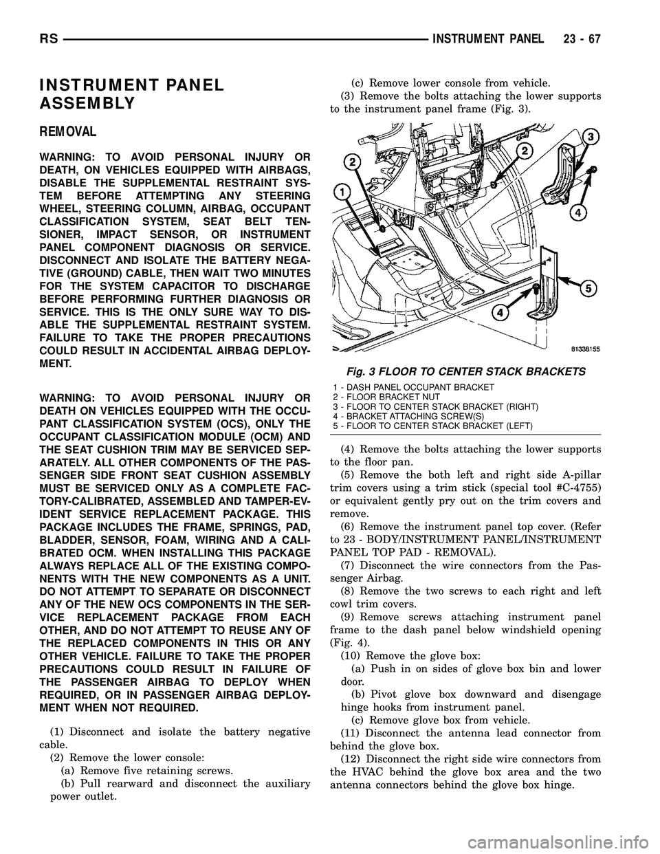
(3) Remove the bolts attaching the lower supports
to the instrument panel frame (Fig. 3).
(4) Remove the bolts attaching the lower supports
to the floor pan.
(5) Remove the both left and right side A-pillar
trim covers using a trim stick (special tool #C-4755)
or equivalent gently pry out on the trim covers and
remove.
(6) Remove the instrument panel top cover. (Refer
to 23 - BODY/INSTRUMENT PANEL/INSTRUMENT
PANEL TOP PAD - REMOVAL).
(7) Disconnect the wire connectors from the Pas-
senger Airbag.
(8) Remove the two screws to each right and left
cowl trim covers.
(9) Remove screws attaching instrument panel
frame to the dash panel below windshield opening
(Fig. 4).
(10) Remove the glove box:
(a) Push in on sides of glove box bin and lower
door.
(b) Pivot glove box downward and disengage
hinge hooks from instrument panel.
(c) Remove glove box from vehicle.
(11) Disconnect the antenna lead connector from
behind the glove box.
(12) Disconnect the right side wire connectors from
the HVAC behind the glove box area and the two
antenna connectors behind the glove box hinge.
Fig. 3 FLOOR TO CENTER STACK BRACKETS
1 - DASH PANEL OCCUPANT BRACKET
2 - FLOOR BRACKET NUT
3 - FLOOR TO CENTER STACK BRACKET (RIGHT)
4 - BRACKET ATTACHING SCREW(S)
5 - FLOOR TO CENTER STACK BRACKET (LEFT)
RSINSTRUMENT PANEL23-67
Page 1849 of 2339
(29) Remove both the left and right power mirrors:
(a) Using a trim stick or equivalent, gently pry
out on mirror trim cover.
(b) Open door and remove the three torx retain-
ing screws.
(c) Disconnect the wire connector and remove
mirror from the vehicle.
(30) Feed power mirror wire harness inboard
through the A-pillar.
(31) Loosen the left side roll down bolt (Fig. 8).
(32) Remove the left side A-pillar retaining bolts.
There are two 13 mm bolts and one 10 mm bolt (Fig.
8).
(33) With the help of an assistant remove the
instrument panel from vehicle. Lift the instrument
panel up off the HVAC so you won't damage the seal-
ing surface of the distribution duct.
(34) If the instrument panel is being replaced,
transfer all parts to the new instrument panel
assembly.
INSTALLATION
WARNING: TO AVOID PERSONAL INJURY OR
DEATH, ON VEHICLES EQUIPPED WITH AIRBAGS,
DISABLE THE SUPPLEMENTAL RESTRAINT SYS-
TEM BEFORE ATTEMPTING ANY STEERING
WHEEL, STEERING COLUMN, AIRBAG, OCCUPANT
CLASSIFICATION SYSTEM, SEAT BELT TEN-
SIONER, IMPACT SENSOR, OR INSTRUMENT
PANEL COMPONENT DIAGNOSIS OR SERVICE.
DISCONNECT AND ISOLATE THE BATTERY NEGA-
TIVE (GROUND) CABLE, THEN WAIT TWO MINUTESFOR THE SYSTEM CAPACITOR TO DISCHARGE
BEFORE PERFORMING FURTHER DIAGNOSIS OR
SERVICE. THIS IS THE ONLY SURE WAY TO DIS-
ABLE THE SUPPLEMENTAL RESTRAINT SYSTEM.
FAILURE TO TAKE THE PROPER PRECAUTIONS
COULD RESULT IN ACCIDENTAL AIRBAG DEPLOY-
MENT.
WARNING: TO AVOID PERSONAL INJURY OR
DEATH ON VEHICLES EQUIPPED WITH THE OCCU-
PANT CLASSIFICATION SYSTEM (OCS), ONLY THE
OCCUPANT CLASSIFICATION MODULE (OCM) AND
THE SEAT CUSHION TRIM MAY BE SERVICED SEP-
ARATELY. ALL OTHER COMPONENTS OF THE PAS-
SENGER SIDE FRONT SEAT CUSHION ASSEMBLY
MUST BE SERVICED ONLY AS A COMPLETE FAC-
TORY-CALIBRATED, ASSEMBLED AND TAMPER-EV-
IDENT SERVICE REPLACEMENT PACKAGE. THIS
PACKAGE INCLUDES THE FRAME, SPRINGS, PAD,
BLADDER, SENSOR, FOAM, WIRING AND A CALI-
BRATED OCM. WHEN INSTALLING THIS PACKAGE
ALWAYS REPLACE ALL OF THE EXISTING COMPO-
NENTS WITH THE NEW COMPONENTS AS A UNIT.
DO NOT ATTEMPT TO SEPARATE OR DISCONNECT
ANY OF THE NEW OCS COMPONENTS IN THE SER-
VICE REPLACEMENT PACKAGE FROM EACH
OTHER, AND DO NOT ATTEMPT TO REUSE ANY OF
THE REPLACED COMPONENTS IN THIS OR ANY
OTHER VEHICLE. FAILURE TO TAKE THE PROPER
PRECAUTIONS COULD RESULT IN FAILURE OF
THE PASSENGER AIRBAG TO DEPLOY WHEN
REQUIRED, OR IN PASSENGER AIRBAG DEPLOY-
MENT WHEN NOT REQUIRED.
(1) With the help of an assistant place the instru-
ment panel into vehicle on roll down bolts. As you
roll the instrument panel up, lift the instrument
panel up so the duct work does not bind or bend and
you can set it down on the HVAC housing to get the
proper seal at the distribution duct. Get one bolt
started in the dash panel.
(2) Start the locator screw and install the right
side A-pillar retaining bolts (Fig. 5). There are two 13
mm bolts and one 10 mm bolt.
(3) Install the left side A-pillar retaining bolts.
There are two 13 mm bolts and one 10 mm bolt (Fig.
8).
(4) Tighten the right and left side cowl side roll
down bolt.
(5) Feed power mirror wire harness outboard
through the A-pillar.
(6) Install both the left and right power mirrors:
(a) Connect the wire connector and install the
mirror onto the vehicle.
(b) Install the three torx retaining screws.
(c) Using a firm push, snap the mirror trim
cover into place.
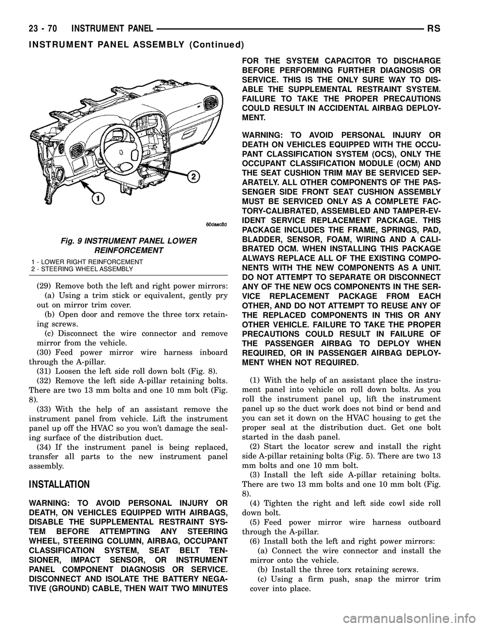
Fig. 9 INSTRUMENT PANEL LOWER
REINFORCEMENT
1 - LOWER RIGHT REINFORCEMENT
2 - STEERING WHEEL ASSEMBLY
23 - 70 INSTRUMENT PANELRS
INSTRUMENT PANEL ASSEMBLY (Continued)
Page 1853 of 2339
LOWER STEERING COLUMN
COVER
REMOVAL
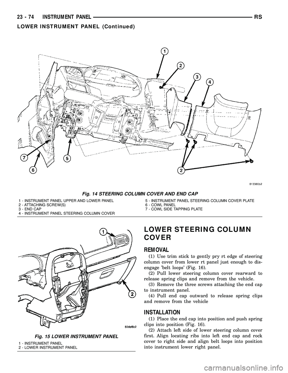
(1) Use trim stick to gently pry rt edge of steering
column cover from lower rt panel just enough to dis-
engage 'belt loops' (Fig. 16).
(2) Pull lower steering column cover rearward to
release spring clips and remove from the vehicle.
(3) Remove the three screws attaching the end cap
to instrument panel.
(4) Pull end cap outward to release spring clips
and remove from the vehicle
INSTALLATION
(1) Place the end cap into position and push spring
clips into position (Fig. 16).
(2) Attach left side of lower steering column cover
first. Align locating ribs into left end cap and rock
cover to right side and align belt loops into position
into instrument lower right panel.
Fig. 14 STEERING COLUMN COVER AND END CAP
1 - INSTRUMENT PANEL UPPER AND LOWER PANEL
2 - ATTACHING SCREW(S)
3 - END CAP
4 - INSTRUMENT PANEL STEERING COLUMN COVER5 - INSTRUMENT PANEL STEERING COLUMN COVER PLATE
6 - COWL PANEL
7 - COWL SIDE TAPPING PLATE
Fig. 15 LOWER INSTRUMENT PANEL
1 - INSTRUMENT PANEL
2 - LOWER INSTRUMENT PANEL
23 - 74 INSTRUMENT PANELRS
LOWER INSTRUMENT PANEL (Continued)
Page 1858 of 2339
A-PILLAR LOWER EXTENSION
TRIM
REMOVAL
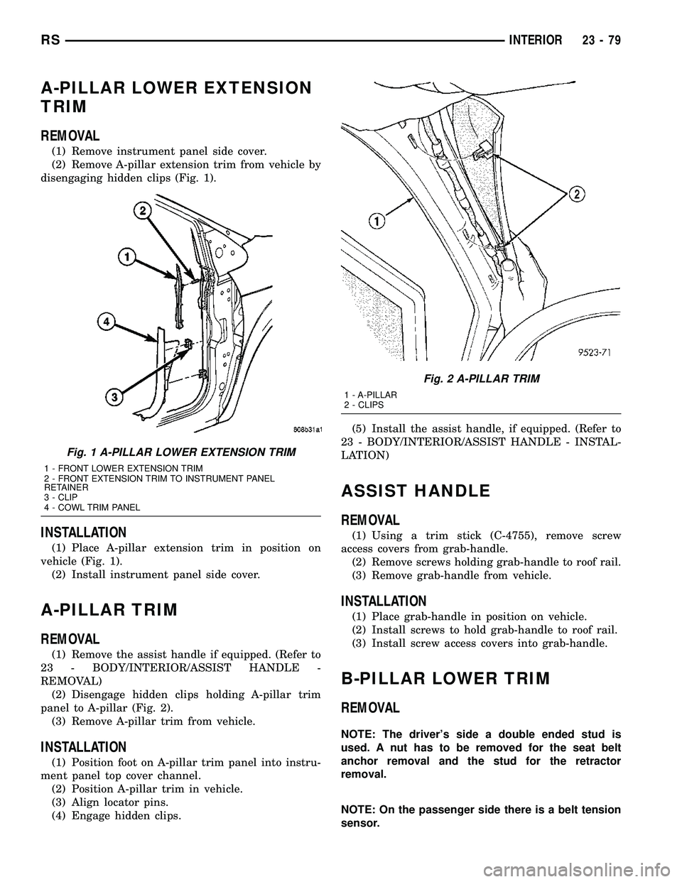
(1) Remove instrument panel side cover.
(2) Remove A-pillar extension trim from vehicle by
disengaging hidden clips (Fig. 1).
INSTALLATION
(1) Place A-pillar extension trim in position on
vehicle (Fig. 1).
(2) Install instrument panel side cover.
A-PILLAR TRIM
REMOVAL
(1) Remove the assist handle if equipped. (Refer to
23 - BODY/INTERIOR/ASSIST HANDLE -
REMOVAL)
(2) Disengage hidden clips holding A-pillar trim
panel to A-pillar (Fig. 2).
(3) Remove A-pillar trim from vehicle.
INSTALLATION
(1) Position foot on A-pillar trim panel into instru-
ment panel top cover channel.
(2) Position A-pillar trim in vehicle.
(3) Align locator pins.
(4) Engage hidden clips.(5) Install the assist handle, if equipped. (Refer to
23 - BODY/INTERIOR/ASSIST HANDLE - INSTAL-
LATION)
ASSIST HANDLE
REMOVAL
(1) Using a trim stick (C-4755), remove screw
access covers from grab-handle.
(2) Remove screws holding grab-handle to roof rail.
(3) Remove grab-handle from vehicle.
INSTALLATION
(1) Place grab-handle in position on vehicle.
(2) Install screws to hold grab-handle to roof rail.
(3) Install screw access covers into grab-handle.
B-PILLAR LOWER TRIM
REMOVAL
NOTE: The driver's side a double ended stud is
used. A nut has to be removed for the seat belt
anchor removal and the stud for the retractor
removal.
NOTE: On the passenger side there is a belt tension
sensor.
Fig. 1 A-PILLAR LOWER EXTENSION TRIM
1 - FRONT LOWER EXTENSION TRIM
2 - FRONT EXTENSION TRIM TO INSTRUMENT PANEL
RETAINER
3 - CLIP
4 - COWL TRIM PANEL
Fig. 2 A-PILLAR TRIM
1 - A-PILLAR
2 - CLIPS
RSINTERIOR23-79
Page 1859 of 2339
(1) Slide lower seat belt cover rearward to expose
anchor fastener.
(2) Remove bolt/nut attaching lower seat belt
anchor to floor.
(3) Remove upper B-pillar trim cover.
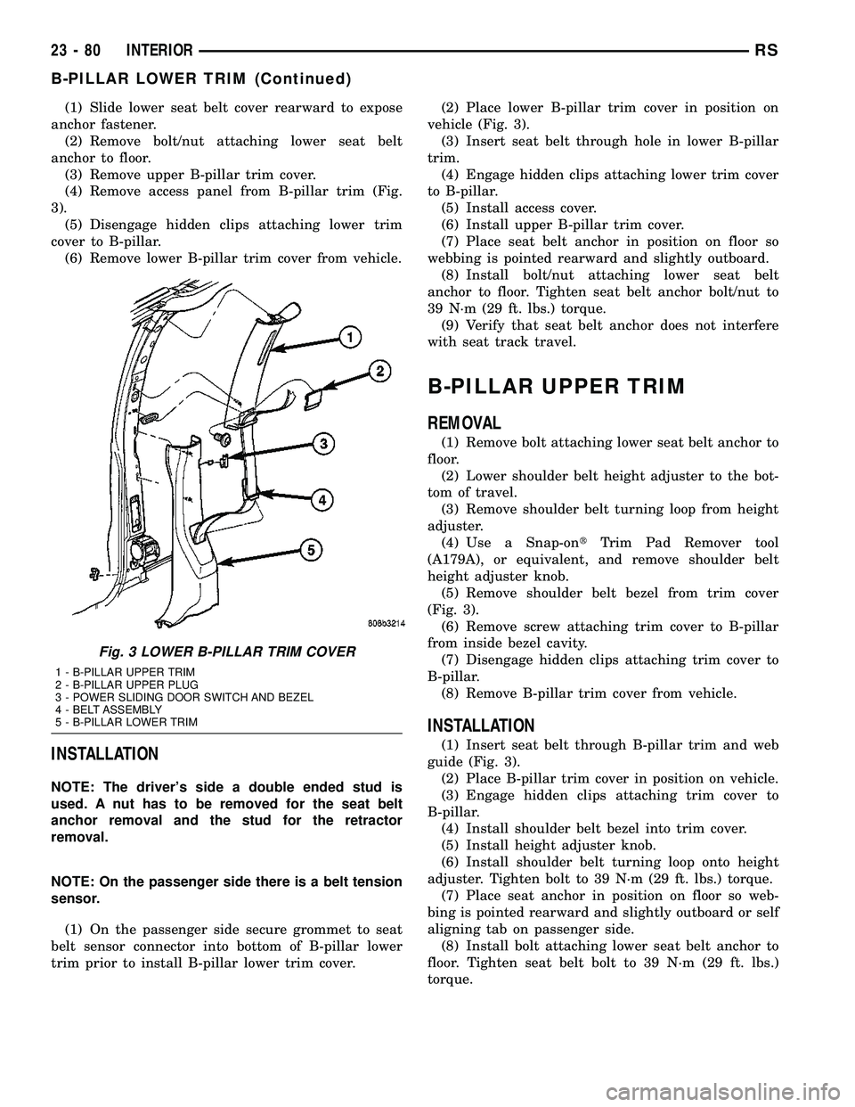
(4) Remove access panel from B-pillar trim (Fig.
3).
(5) Disengage hidden clips attaching lower trim
cover to B-pillar.
(6) Remove lower B-pillar trim cover from vehicle.
INSTALLATION
NOTE: The driver's side a double ended stud is
used. A nut has to be removed for the seat belt
anchor removal and the stud for the retractor
removal.
NOTE: On the passenger side there is a belt tension
sensor.
(1) On the passenger side secure grommet to seat
belt sensor connector into bottom of B-pillar lower
trim prior to install B-pillar lower trim cover.(2) Place lower B-pillar trim cover in position on
vehicle (Fig. 3).
(3) Insert seat belt through hole in lower B-pillar
trim.
(4) Engage hidden clips attaching lower trim cover
to B-pillar.
(5) Install access cover.
(6) Install upper B-pillar trim cover.
(7) Place seat belt anchor in position on floor so
webbing is pointed rearward and slightly outboard.
(8) Install bolt/nut attaching lower seat belt
anchor to floor. Tighten seat belt anchor bolt/nut to
39 N´m (29 ft. lbs.) torque.
(9) Verify that seat belt anchor does not interfere
with seat track travel.
B-PILLAR UPPER TRIM
REMOVAL
(1) Remove bolt attaching lower seat belt anchor to
floor.
(2) Lower shoulder belt height adjuster to the bot-
tom of travel.
(3) Remove shoulder belt turning loop from height
adjuster.
(4) Use a Snap-ontTrim Pad Remover tool
(A179A), or equivalent, and remove shoulder belt
height adjuster knob.
(5) Remove shoulder belt bezel from trim cover
(Fig. 3).
(6) Remove screw attaching trim cover to B-pillar
from inside bezel cavity.
(7) Disengage hidden clips attaching trim cover to
B-pillar.
(8) Remove B-pillar trim cover from vehicle.
INSTALLATION
(1) Insert seat belt through B-pillar trim and web
guide (Fig. 3).
(2) Place B-pillar trim cover in position on vehicle.
(3) Engage hidden clips attaching trim cover to
B-pillar.
(4) Install shoulder belt bezel into trim cover.
(5) Install height adjuster knob.
(6) Install shoulder belt turning loop onto height
adjuster. Tighten bolt to 39 N´m (29 ft. lbs.) torque.
(7) Place seat anchor in position on floor so web-
bing is pointed rearward and slightly outboard or self
aligning tab on passenger side.
(8) Install bolt attaching lower seat belt anchor to
floor. Tighten seat belt bolt to 39 N´m (29 ft. lbs.)
torque.
Fig. 3 LOWER B-PILLAR TRIM COVER
1 - B-PILLAR UPPER TRIM
2 - B-PILLAR UPPER PLUG
3 - POWER SLIDING DOOR SWITCH AND BEZEL
4 - BELT ASSEMBLY
5 - B-PILLAR LOWER TRIM
23 - 80 INTERIORRS
B-PILLAR LOWER TRIM (Continued)
Page 1861 of 2339
CARPETS - FOLD-IN-FLOOR
REMOVAL
(1) Remove floor mats.
(2) Remove front seats. (Refer to 23 - BODY/
SEATS/SEAT - REMOVAL)
(3) Remove instrument panel lower console. (Refer
to 23 - BODY/INSTRUMENT PANEL/STORAGE
BIN - REMOVAL).
(4) Remove the floor console base tray and discon-
nect wire connector from the base tray.(Refer to 23 -
BODY/INTERIOR/FLOOR CONSOLE BASE TRAY -
REMOVAL)
(5) Remove heel blocker (plastic block below accel-
erator pedal).
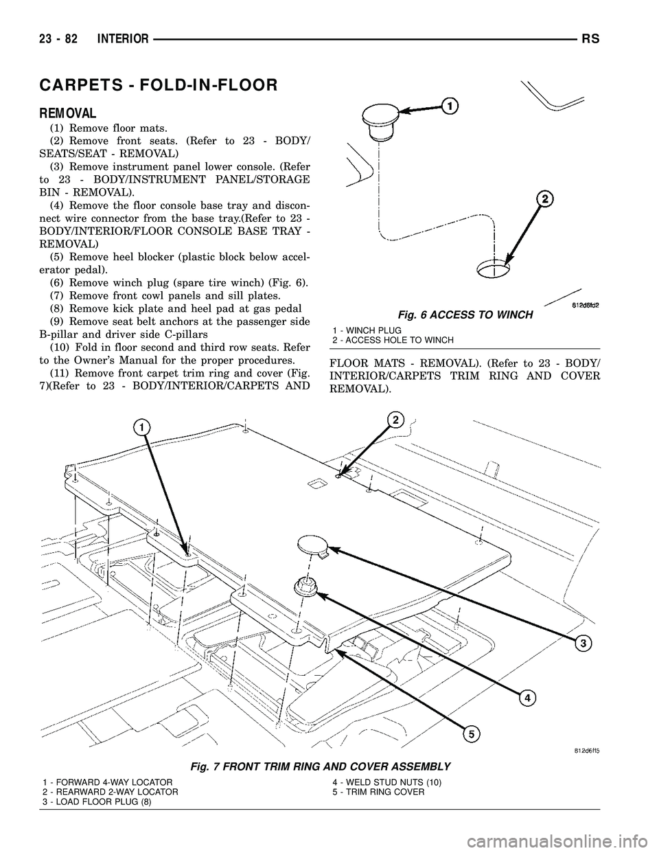
(6) Remove winch plug (spare tire winch) (Fig. 6).
(7) Remove front cowl panels and sill plates.
(8) Remove kick plate and heel pad at gas pedal
(9) Remove seat belt anchors at the passenger side
B-pillar and driver side C-pillars
(10) Fold in floor second and third row seats. Refer
to the Owner's Manual for the proper procedures.
(11) Remove front carpet trim ring and cover (Fig.
7)(Refer to 23 - BODY/INTERIOR/CARPETS ANDFLOOR MATS - REMOVAL). (Refer to 23 - BODY/
INTERIOR/CARPETS TRIM RING AND COVER
REMOVAL).
Fig. 6 ACCESS TO WINCH
1 - WINCH PLUG
2 - ACCESS HOLE TO WINCH
Fig. 7 FRONT TRIM RING AND COVER ASSEMBLY
1 - FORWARD 4-WAY LOCATOR
2 - REARWARD 2-WAY LOCATOR
3 - LOAD FLOOR PLUG (8)4 - WELD STUD NUTS (10)
5 - TRIM RING COVER
23 - 82 INTERIORRS