2005 CHRYSLER CARAVAN belt
[x] Cancel search: beltPage 1789 of 2339
(a) If the heat staked or component seam loca-
tion is loose, hold the two components tightly
together and using a soldering gun with a flat tip,
melt the material securing the components
together. Do not over heat the affected area, dam-
age to the exterior of the trim panel may occur.
(b) If the heat staked material is broken or miss-
ing, use a hot glue gun to apply new material to
the area to be repaired. The panels that are being
heat staked must be held together while the apply-ing the glue. Once the new material is in place, it
may be necessary to use a soldering gun to melt
the newly applied material. Do not over heat the
affected area, damage to the exterior of the trim
panel may occur.
(4) Allow the repaired area to cool and verify the
repair.
(5) Install trim panel.
SPECIFICATIONS
TORQUE
TORQUE SPECIFICATIONS
DESCRIPTION N´m Ft. Lbs. In. Lbs.
All seat belt anchor bolts 39 29 Ð
Armrest shoulder bolt 29 21 Ð
Bench seat riser bolts 48 35 Ð
Bench seat track nuts 48 35 Ð
Quad bucket seat track to cushion frame bolts 40 30 Ð
Bucket seat back pivot bolts 33 24 Ð
Center seat to seat track bolts 24 17 Ð
Child seat module screws (bench seats) 7 Ð 62
Child seat module screws (quad seats) 13.5 10 Ð
Crossmember to radiator closure panel bolts 28 21 Ð
Door check strap to door end frame 12 Ð 105
Door latch to door end frame bolts 10 Ð 89
Floor latch to seat cushion frame bolts 27 19 Ð
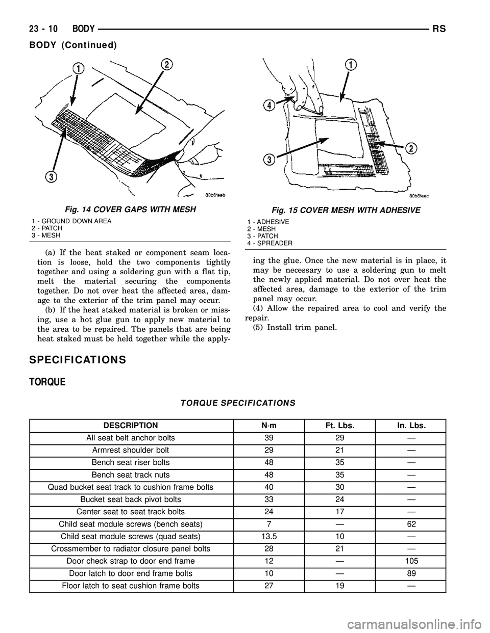
Fig. 14 COVER GAPS WITH MESH
1 - GROUND DOWN AREA
2 - PATCH
3 - MESH
Fig. 15 COVER MESH WITH ADHESIVE
1 - ADHESIVE
2 - MESH
3 - PATCH
4 - SPREADER
23 - 10 BODYRS
BODY (Continued)
Page 1790 of 2339
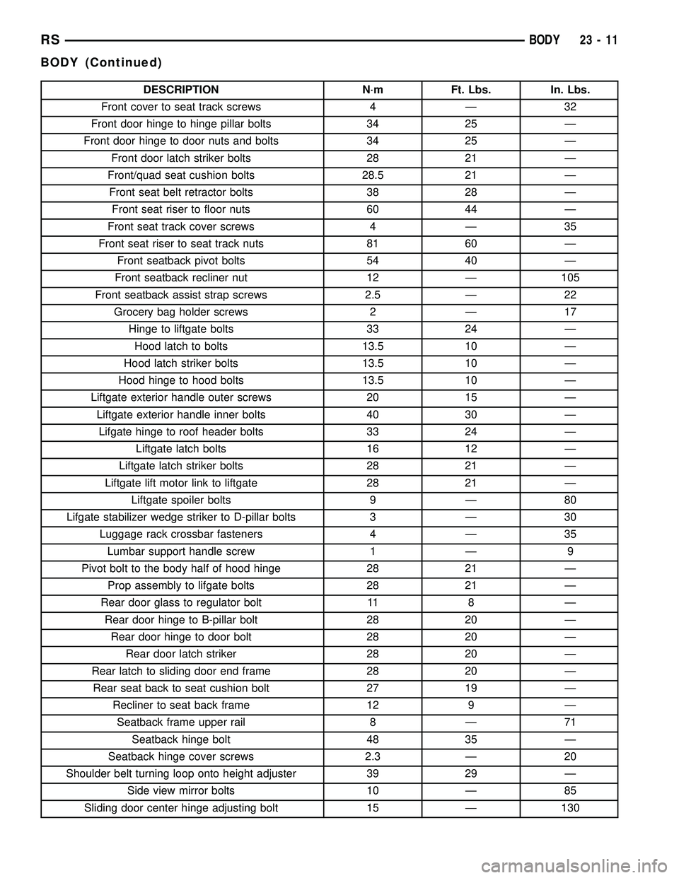
DESCRIPTION N´m Ft. Lbs. In. Lbs.
Front cover to seat track screws 4 Ð 32
Front door hinge to hinge pillar bolts 34 25 Ð
Front door hinge to door nuts and bolts 34 25 Ð
Front door latch striker bolts 28 21 Ð
Front/quad seat cushion bolts 28.5 21 Ð
Front seat belt retractor bolts 38 28 Ð
Front seat riser to floor nuts 60 44 Ð
Front seat track cover screws 4 Ð 35
Front seat riser to seat track nuts 81 60 Ð
Front seatback pivot bolts 54 40 Ð
Front seatback recliner nut 12 Ð 105
Front seatback assist strap screws 2.5 Ð 22
Grocery bag holder screws 2 Ð 17
Hinge to liftgate bolts 33 24 Ð
Hood latch to bolts 13.5 10 Ð
Hood latch striker bolts 13.5 10 Ð
Hood hinge to hood bolts 13.5 10 Ð
Liftgate exterior handle outer screws 20 15 Ð
Liftgate exterior handle inner bolts 40 30 Ð
Lifgate hinge to roof header bolts 33 24 Ð
Liftgate latch bolts 16 12 Ð
Liftgate latch striker bolts 28 21 Ð
Liftgate lift motor link to liftgate 28 21 Ð
Liftgate spoiler bolts 9 Ð 80
Lifgate stabilizer wedge striker to D-pillar bolts 3 Ð 30
Luggage rack crossbar fasteners 4 Ð 35
Lumbar support handle screw 1 Ð 9
Pivot bolt to the body half of hood hinge 28 21 Ð
Prop assembly to lifgate bolts 28 21 Ð
Rear door glass to regulator bolt 11 8 Ð
Rear door hinge to B-pillar bolt 28 20 Ð
Rear door hinge to door bolt 28 20 Ð
Rear door latch striker 28 20 Ð
Rear latch to sliding door end frame 28 20 Ð
Rear seat back to seat cushion bolt 27 19 Ð
Recliner to seat back frame 12 9 Ð
Seatback frame upper rail 8 Ð 71
Seatback hinge bolt 48 35 Ð
Seatback hinge cover screws 2.3 Ð 20
Shoulder belt turning loop onto height adjuster 39 29 Ð
Side view mirror bolts 10 Ð 85
Sliding door center hinge adjusting bolt 15 Ð 130
RSBODY23-11
BODY (Continued)
Page 1792 of 2339
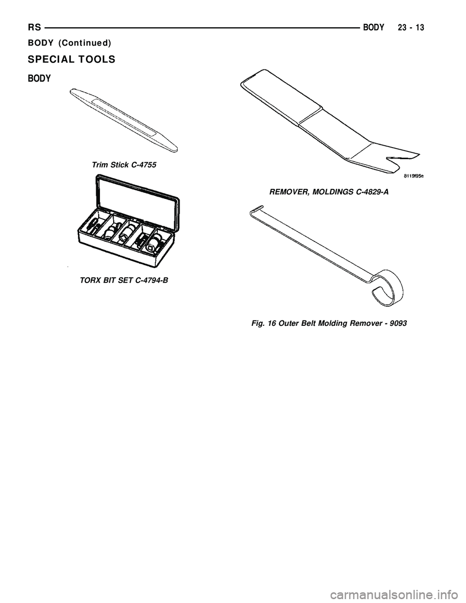
SPECIAL TOOLS
BODY
Trim Stick C-4755
TORX BIT SET C-4794-B
REMOVER, MOLDINGS C-4829-A
Fig. 16 Outer Belt Molding Remover - 9093
RSBODY23-13
BODY (Continued)
Page 1793 of 2339
DOOR - FRONT
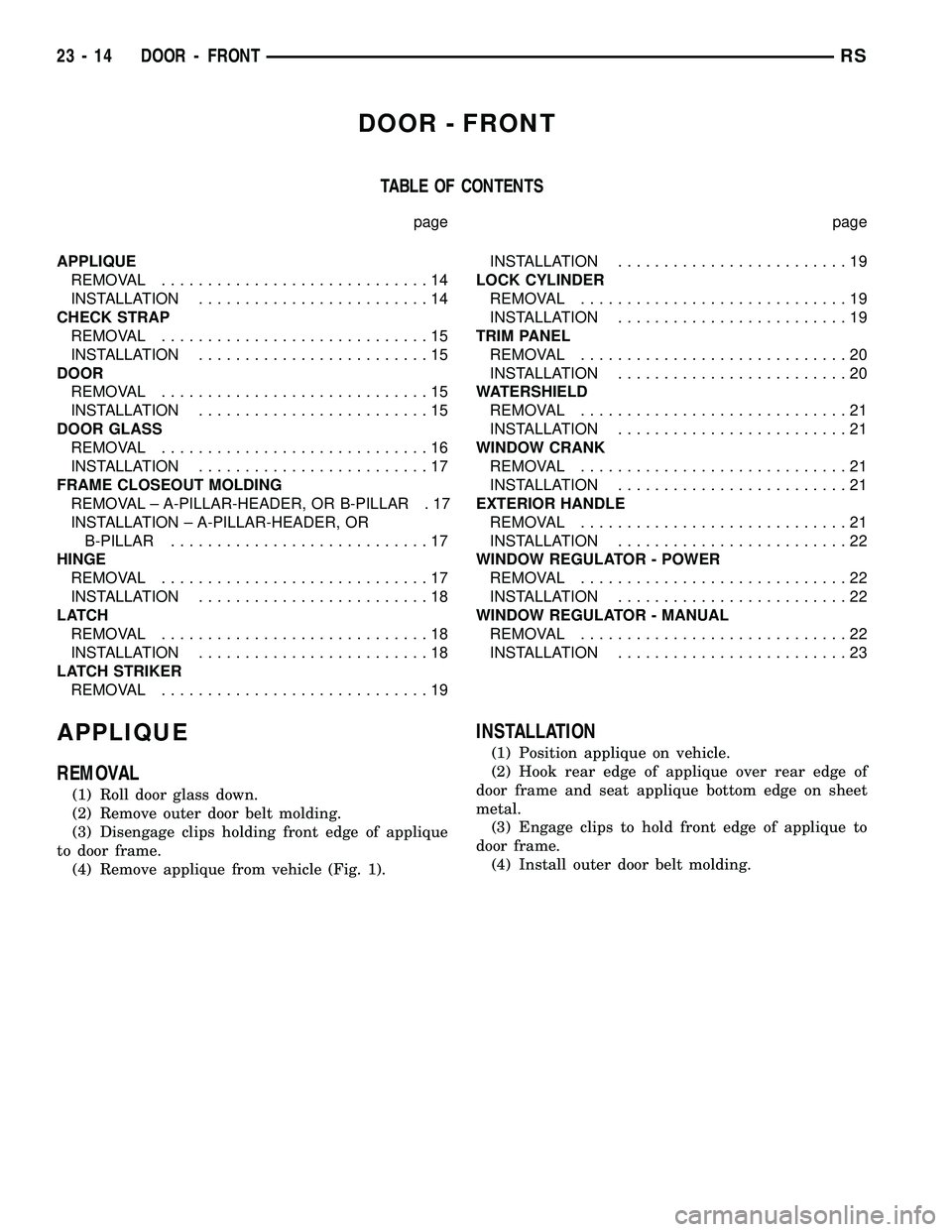
TABLE OF CONTENTS
page page
APPLIQUE
REMOVAL.............................14
INSTALLATION.........................14
CHECK STRAP
REMOVAL.............................15
INSTALLATION.........................15
DOOR
REMOVAL.............................15
INSTALLATION.........................15
DOOR GLASS
REMOVAL.............................16
INSTALLATION.........................17
FRAME CLOSEOUT MOLDING
REMOVAL ± A-PILLAR-HEADER, OR B-PILLAR . 17
INSTALLATION ± A-PILLAR-HEADER, OR
B-PILLAR............................17
HINGE
REMOVAL.............................17
INSTALLATION.........................18
LATCH
REMOVAL.............................18
INSTALLATION.........................18
LATCH STRIKER
REMOVAL.............................19INSTALLATION.........................19
LOCK CYLINDER
REMOVAL.............................19
INSTALLATION.........................19
TRIM PANEL
REMOVAL.............................20
INSTALLATION.........................20
WATERSHIELD
REMOVAL.............................21
INSTALLATION.........................21
WINDOW CRANK
REMOVAL.............................21
INSTALLATION.........................21
EXTERIOR HANDLE
REMOVAL.............................21
INSTALLATION.........................22
WINDOW REGULATOR - POWER
REMOVAL.............................22
INSTALLATION.........................22
WINDOW REGULATOR - MANUAL
REMOVAL.............................22
INSTALLATION.........................23
APPLIQUE
REMOVAL
(1) Roll door glass down.
(2) Remove outer door belt molding.
(3) Disengage clips holding front edge of applique
to door frame.
(4) Remove applique from vehicle (Fig. 1).
INSTALLATION
(1) Position applique on vehicle.
(2) Hook rear edge of applique over rear edge of
door frame and seat applique bottom edge on sheet
metal.
(3) Engage clips to hold front edge of applique to
door frame.
(4) Install outer door belt molding.
23 - 14 DOOR - FRONTRS
Page 1795 of 2339
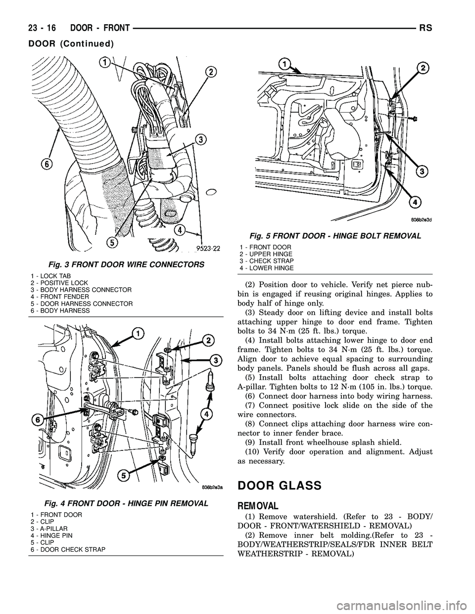
(2) Position door to vehicle. Verify net pierce nub-
bin is engaged if reusing original hinges. Applies to
body half of hinge only.
(3) Steady door on lifting device and install bolts
attaching upper hinge to door end frame. Tighten
bolts to 34 N´m (25 ft. lbs.) torque.
(4) Install bolts attaching lower hinge to door end
frame. Tighten bolts to 34 N´m (25 ft. lbs.) torque.
Align door to achieve equal spacing to surrounding
body panels. Panels should be flush across all gaps.
(5) Install bolts attaching door check strap to
A-pillar. Tighten bolts to 12 N´m (105 in. lbs.) torque.
(6) Connect door harness into body wiring harness.
(7) Connect positive lock slide on the side of the
wire connectors.
(8) Connect clips attaching door harness wire con-
nector to inner fender brace.
(9) Install front wheelhouse splash shield.
(10) Verify door operation and alignment. Adjust
as necessary.
DOOR GLASS
REMOVAL
(1) Remove watershield. (Refer to 23 - BODY/
DOOR - FRONT/WATERSHIELD - REMOVAL)
(2) Remove inner belt molding.(Refer to 23 -
BODY/WEATHERSTRIP/SEALS/FDR INNER BELT
WEATHERSTRIP - REMOVAL)
Fig. 3 FRONT DOOR WIRE CONNECTORS
1 - LOCK TAB
2 - POSITIVE LOCK
3 - BODY HARNESS CONNECTOR
4 - FRONT FENDER
5 - DOOR HARNESS CONNECTOR
6 - BODY HARNESS
Fig. 4 FRONT DOOR - HINGE PIN REMOVAL
1 - FRONT DOOR
2 - CLIP
3 - A-PILLAR
4 - HINGE PIN
5 - CLIP
6 - DOOR CHECK STRAP
Fig. 5 FRONT DOOR - HINGE BOLT REMOVAL
1 - FRONT DOOR
2 - UPPER HINGE
3 - CHECK STRAP
4 - LOWER HINGE
23 - 16 DOOR - FRONTRS
DOOR (Continued)
Page 1796 of 2339
(3) Position glass to gain access to front and rear
regulator lift plates through front and rear access
holes in door panel.
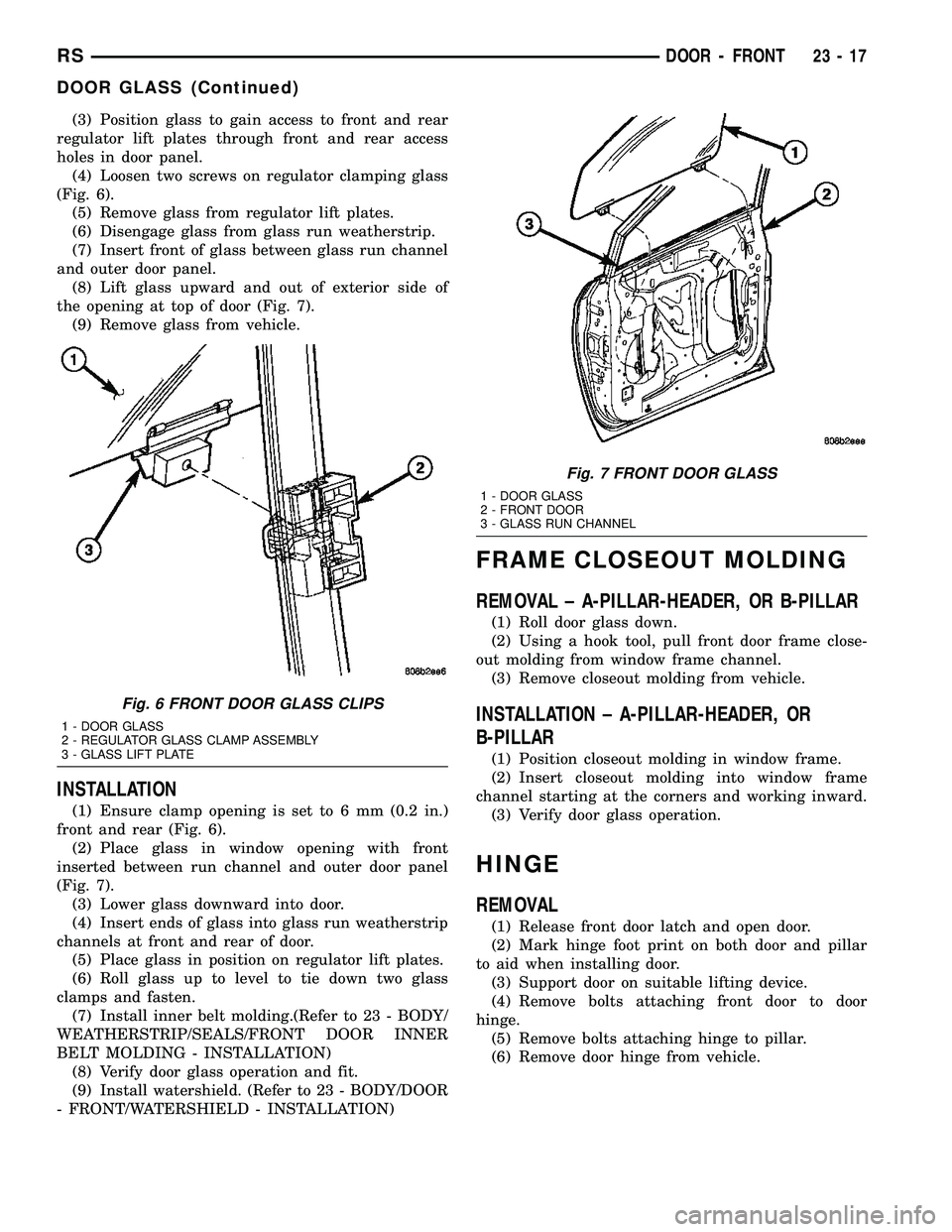
(4) Loosen two screws on regulator clamping glass
(Fig. 6).
(5) Remove glass from regulator lift plates.
(6) Disengage glass from glass run weatherstrip.
(7) Insert front of glass between glass run channel
and outer door panel.
(8) Lift glass upward and out of exterior side of
the opening at top of door (Fig. 7).
(9) Remove glass from vehicle.
INSTALLATION
(1) Ensure clamp opening is set to 6 mm (0.2 in.)
front and rear (Fig. 6).
(2) Place glass in window opening with front
inserted between run channel and outer door panel
(Fig. 7).
(3) Lower glass downward into door.
(4) Insert ends of glass into glass run weatherstrip
channels at front and rear of door.
(5) Place glass in position on regulator lift plates.
(6) Roll glass up to level to tie down two glass
clamps and fasten.
(7) Install inner belt molding.(Refer to 23 - BODY/
WEATHERSTRIP/SEALS/FRONT DOOR INNER
BELT MOLDING - INSTALLATION)
(8) Verify door glass operation and fit.
(9) Install watershield. (Refer to 23 - BODY/DOOR
- FRONT/WATERSHIELD - INSTALLATION)
FRAME CLOSEOUT MOLDING
REMOVAL ± A-PILLAR-HEADER, OR B-PILLAR
(1) Roll door glass down.
(2) Using a hook tool, pull front door frame close-
out molding from window frame channel.
(3) Remove closeout molding from vehicle.
INSTALLATION ± A-PILLAR-HEADER, OR
B-PILLAR
(1) Position closeout molding in window frame.
(2) Insert closeout molding into window frame
channel starting at the corners and working inward.
(3) Verify door glass operation.
HINGE
REMOVAL
(1) Release front door latch and open door.
(2) Mark hinge foot print on both door and pillar
to aid when installing door.
(3) Support door on suitable lifting device.
(4) Remove bolts attaching front door to door
hinge.
(5) Remove bolts attaching hinge to pillar.
(6) Remove door hinge from vehicle.
Fig. 6 FRONT DOOR GLASS CLIPS
1 - DOOR GLASS
2 - REGULATOR GLASS CLAMP ASSEMBLY
3 - GLASS LIFT PLATE
Fig. 7 FRONT DOOR GLASS
1 - DOOR GLASS
2 - FRONT DOOR
3 - GLASS RUN CHANNEL
RSDOOR - FRONT23-17
DOOR GLASS (Continued)
Page 1799 of 2339
TRIM PANEL
REMOVAL
(1) Remove the plug and remove screw attaching
door pull cup to inner door panel.
(2) Remove switch bezel and disconnect power win-
dow/memory switch.
(3) Remove screws attaching trim panel to door
from below map pocket.
(4) If equipped, remove window crank. (Refer to 23
- BODY/DOOR - FRONT/WINDOW CRANK -
REMOVAL)
(5) Remove screw holding door trim to door panel
from behind inside latch release handle.
(6) Disengage clips attaching door trim to door
frame around perimeter of panel.
(7) Lift trim panel upward to disengage flange
from inner belt molding at top of door.
(8) Tilt top of trim panel away from door to gain
access to latch linkage.
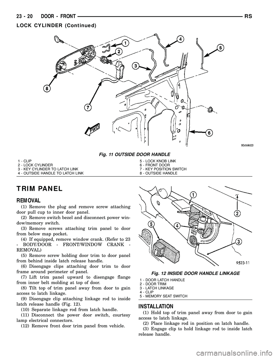
(9) Disengage clip attaching linkage rod to inside
latch release handle (Fig. 12).
(10) Separate linkage rod from latch handle.
(11) Disconnect the power door switch, courtesy
lamp electrical connectors.
(12) Remove front door trim panel from vehicle.
INSTALLATION
(1) Hold top of trim panel away from door to gain
access to latch linkage.
(2) Place linkage rod in position on latch handle.
(3) Engage clip to hold linkage rod to inside latch
release handle.
Fig. 11 OUTSIDE DOOR HANDLE
1 - CLIP
2 - LOCK CYLINDER
3 - KEY CYLINDER TO LATCH LINK
4 - OUTSIDE HANDLE TO LATCH LINK5 - LOCK KNOB LINK
6 - FRONT DOOR
7 - KEY POSITION SWITCH
8 - OUTSIDE HANDLE
Fig. 12 INSIDE DOOR HANDLE LINKAGE
1 - DOOR LATCH HANDLE
2 - DOOR TRIM
3 - LATCH LINKAGE
4 - CLIP
5 - MEMORY SEAT SWITCH
23 - 20 DOOR - FRONTRS
LOCK CYLINDER (Continued)
Page 1800 of 2339
(4) Place front door trim panel in position on door.
(5) Install trim panel into inner belt molding at
top of door.
(6) Install clips to attach door trim to door frame
around perimeter of panel.
(7) If equipped, install screw to attach door trim to
door panel behind inside latch release handle.
(8) If equipped, connect power switch into wire
connector.
(9) Place power accessary switch in position on
door trim.
(10) Connect wire connector into memory seat/mir-
ror switch and install switch into trim panel.
(11) Install screws to attach accessary switch
panel to door trim.
(12) Install screw cover into switch panel.
(13) If equipped, install window crank.
(14) If equipped, install screws to attach trim
panel to door inside map pocket.
(15) If equipped, install screw to attach door pull
cup to inner door panel.
(16) If equipped, install screws to attach door
assist handle to inner door panel.
(17) Connect wire connector into courtesy lamp.
(18) Install lamp in door trim.
(19) Install switch bezel.
WATERSHIELD
REMOVAL
(1) Remove door trim panel. (Refer to 23 - BODY/
DOOR - FRONT/TRIM PANEL - REMOVAL)
(2) Remove the front door speaker. (Refer to 8 -
ELECTRICAL/AUDIO/SPEAKER - REMOVAL)
(3) Peel watershield away from adhesive around
perimeter of inner door panel.
INSTALLATION
(1) Insure that enough adhesive remains to
securely retain the water dam. Replace as necessary.
(2) Place the shield into position and press
securely to adhesive making sure to properly route
wiring and linkages.
(3) Install the front door speaker. (Refer to 8 -
ELECTRICAL/AUDIO/SPEAKER - INSTALLATION)
(4) Install door trim panel. (Refer to 23 - BODY/
DOOR - FRONT/TRIM PANEL - INSTALLATION)
WINDOW CRANK
REMOVAL
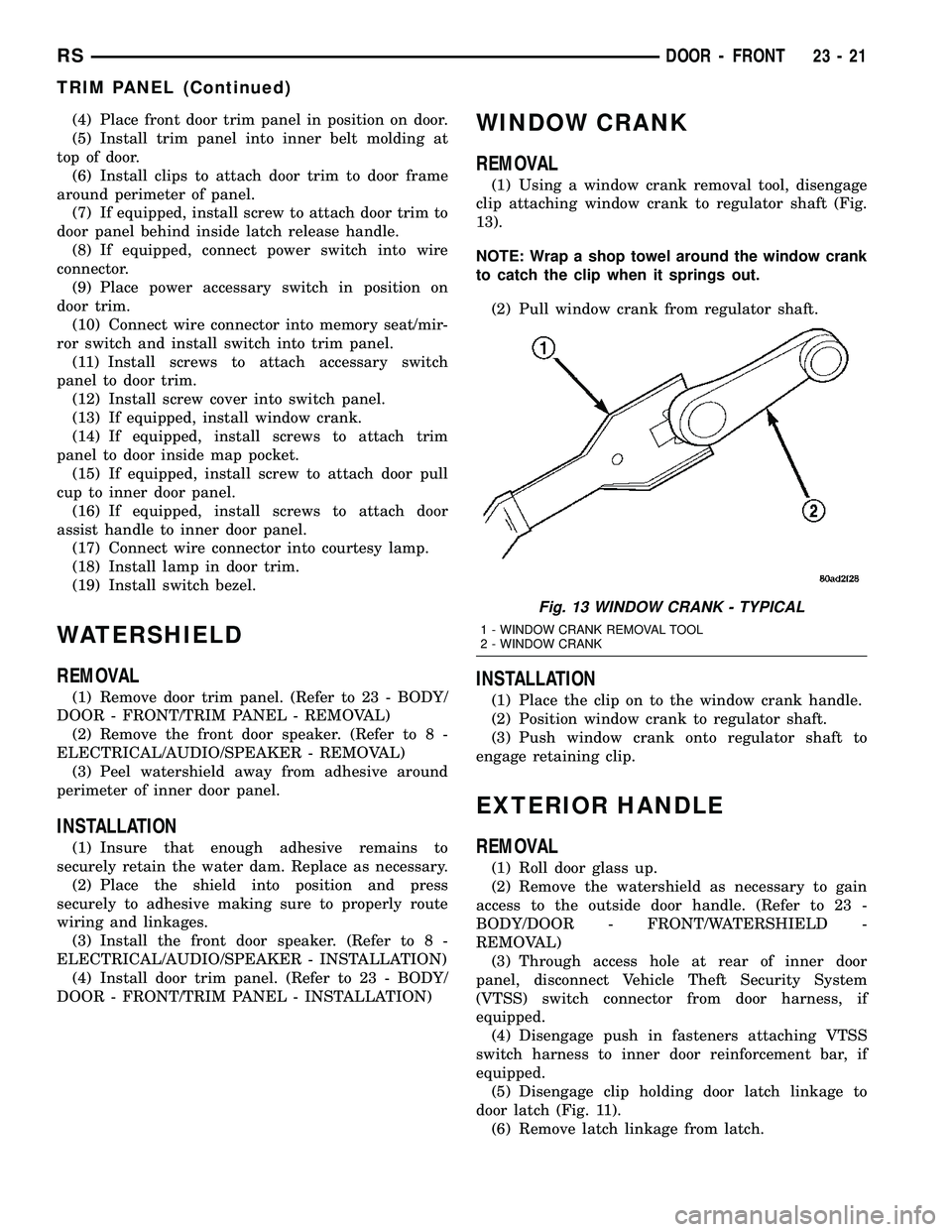
(1) Using a window crank removal tool, disengage
clip attaching window crank to regulator shaft (Fig.
13).
NOTE: Wrap a shop towel around the window crank
to catch the clip when it springs out.
(2) Pull window crank from regulator shaft.
INSTALLATION
(1) Place the clip on to the window crank handle.
(2) Position window crank to regulator shaft.
(3) Push window crank onto regulator shaft to
engage retaining clip.
EXTERIOR HANDLE
REMOVAL
(1) Roll door glass up.
(2) Remove the watershield as necessary to gain
access to the outside door handle. (Refer to 23 -
BODY/DOOR - FRONT/WATERSHIELD -
REMOVAL)
(3) Through access hole at rear of inner door
panel, disconnect Vehicle Theft Security System
(VTSS) switch connector from door harness, if
equipped.
(4) Disengage push in fasteners attaching VTSS
switch harness to inner door reinforcement bar, if
equipped.
(5) Disengage clip holding door latch linkage to
door latch (Fig. 11).
(6) Remove latch linkage from latch.
Fig. 13 WINDOW CRANK - TYPICAL
1 - WINDOW CRANK REMOVAL TOOL
2 - WINDOW CRANK
RSDOOR - FRONT23-21
TRIM PANEL (Continued)