2005 CHRYSLER CARAVAN belt
[x] Cancel search: beltPage 1936 of 2339
INSTALLATION
(1) Place seat back frame into position.
(2) Install two bolts on each side of seat back
frame.
(3) Install strap at top of frame (Fig. 123).
(4) Install seat back cover and foam. (Refer to 23 -
BODY/SEATS/SEAT BACK COVER - INSTALLA-
TION).
SEAT BELT CENTER LAP BELT
- FOLD-IN-FLOOR
REMOVAL
(1) Set third row seat in the upright position.
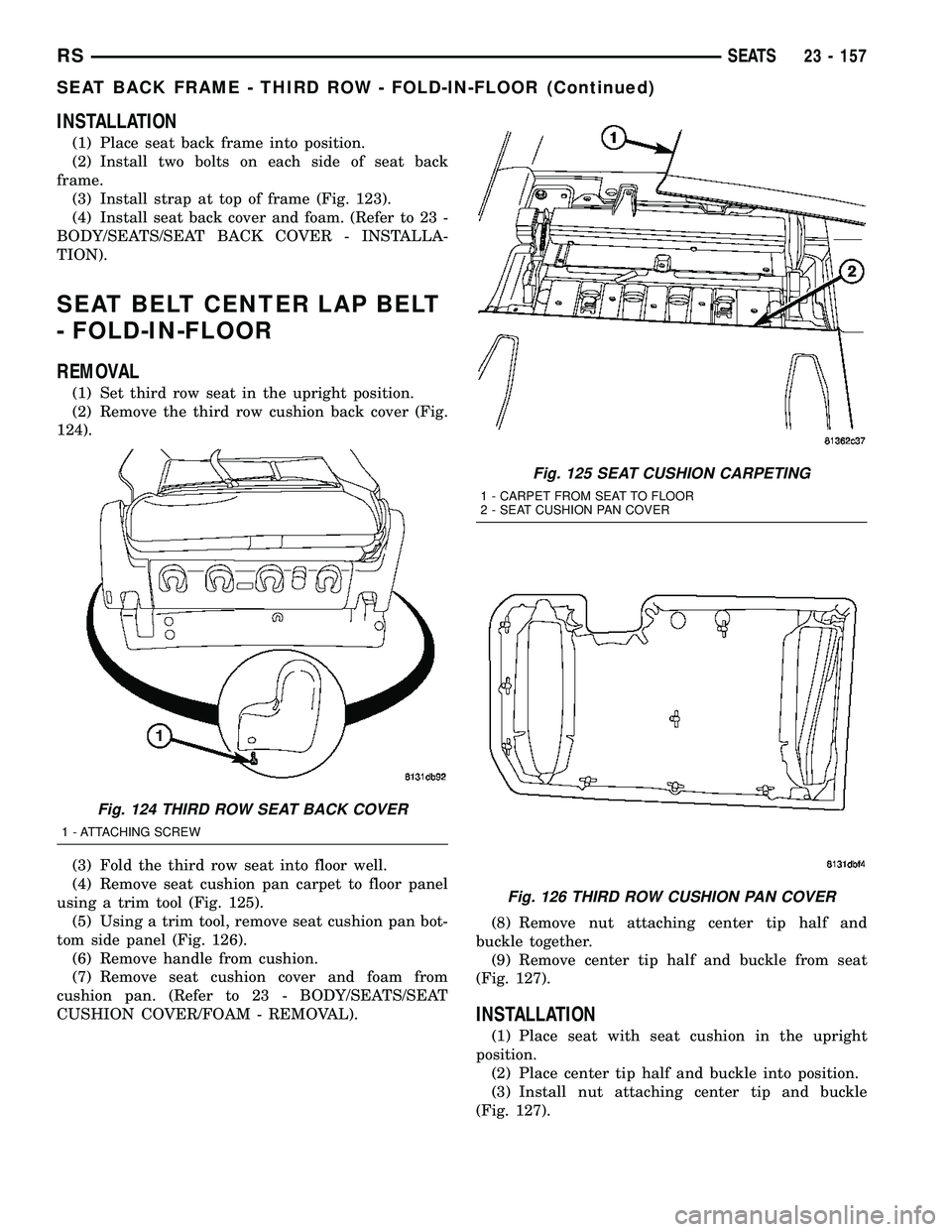
(2) Remove the third row cushion back cover (Fig.
124).
(3) Fold the third row seat into floor well.
(4) Remove seat cushion pan carpet to floor panel
using a trim tool (Fig. 125).
(5) Using a trim tool, remove seat cushion pan bot-
tom side panel (Fig. 126).
(6) Remove handle from cushion.
(7) Remove seat cushion cover and foam from
cushion pan. (Refer to 23 - BODY/SEATS/SEAT
CUSHION COVER/FOAM - REMOVAL).(8) Remove nut attaching center tip half and
buckle together.
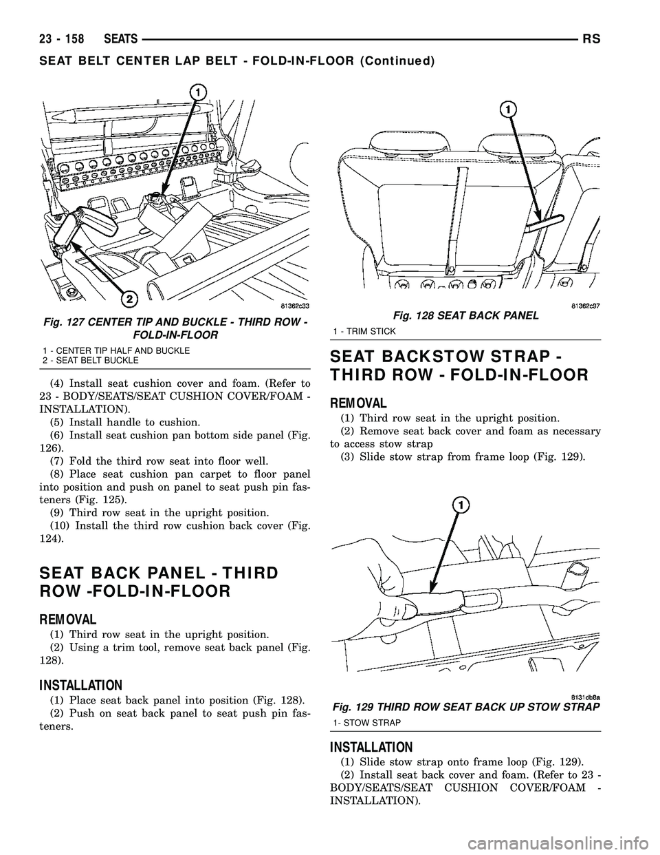
(9) Remove center tip half and buckle from seat
(Fig. 127).
INSTALLATION
(1) Place seat with seat cushion in the upright
position.
(2) Place center tip half and buckle into position.
(3) Install nut attaching center tip and buckle
(Fig. 127).
Fig. 124 THIRD ROW SEAT BACK COVER
1 - ATTACHING SCREW
Fig. 125 SEAT CUSHION CARPETING
1 - CARPET FROM SEAT TO FLOOR
2 - SEAT CUSHION PAN COVER
Fig. 126 THIRD ROW CUSHION PAN COVER
RSSEATS23 - 157
SEAT BACK FRAME - THIRD ROW - FOLD-IN-FLOOR (Continued)
Page 1937 of 2339
(4) Install seat cushion cover and foam. (Refer to
23 - BODY/SEATS/SEAT CUSHION COVER/FOAM -
INSTALLATION).
(5) Install handle to cushion.
(6) Install seat cushion pan bottom side panel (Fig.
126).
(7) Fold the third row seat into floor well.
(8) Place seat cushion pan carpet to floor panel
into position and push on panel to seat push pin fas-
teners (Fig. 125).
(9) Third row seat in the upright position.
(10) Install the third row cushion back cover (Fig.
124).
SEAT BACK PANEL - THIRD
ROW -FOLD-IN-FLOOR
REMOVAL
(1) Third row seat in the upright position.
(2) Using a trim tool, remove seat back panel (Fig.
128).
INSTALLATION
(1) Place seat back panel into position (Fig. 128).
(2) Push on seat back panel to seat push pin fas-
teners.
SEAT BACKSTOW STRAP -
THIRD ROW - FOLD-IN-FLOOR
REMOVAL
(1) Third row seat in the upright position.
(2) Remove seat back cover and foam as necessary
to access stow strap
(3) Slide stow strap from frame loop (Fig. 129).
INSTALLATION
(1) Slide stow strap onto frame loop (Fig. 129).
(2) Install seat back cover and foam. (Refer to 23 -
BODY/SEATS/SEAT CUSHION COVER/FOAM -
INSTALLATION).
Fig. 127 CENTER TIP AND BUCKLE - THIRD ROW -
FOLD-IN-FLOOR
1 - CENTER TIP HALF AND BUCKLE
2 - SEAT BELT BUCKLE
Fig. 128 SEAT BACK PANEL
1 - TRIM STICK
Fig. 129 THIRD ROW SEAT BACK UP STOW STRAP
1- STOW STRAP
23 - 158 SEATSRS
SEAT BELT CENTER LAP BELT - FOLD-IN-FLOOR (Continued)
Page 1945 of 2339
WEATHERSTRIP/SEALS
TABLE OF CONTENTS
page page
FRONT DOOR GLASS RUN WEATHERSTRIP
REMOVAL............................166
INSTALLATION........................166
FRONT DOOR OUTER BELT MOLDING
REMOVAL............................167
INSTALLATION........................167
FRONT DOOR WEATHERSTRIP
REMOVAL............................168INSTALLATION........................168
SLIDING DOOR WEATHERSTRIP
REMOVAL............................168
INSTALLATION........................168
FRONT DOOR INNER BELT MOLDING
REMOVAL............................168
INSTALLATION........................168
FRONT DOOR GLASS RUN
WEATHERSTRIP
REMOVAL
(1) Remove door frame closeout moldings.
(2) Pull weatherstrip from glass run channel at
rear of door frame, working from the bottom to the
top.
(3) Disengage clip attaching weatherstrip to door
frame.
(4) Pull weatherstrip from lip along top of door
frame (Fig. 1).
(5) Remove door trim panel.
(6) Remove door speaker, if equipped.
(7) Remove watershed as necessary to gain access
to screw attaching front lower corner of glass run
weatherstrip to inner door panel.
(8) Remove screw attaching glass run weatherstrip
to inner door panel.
(9) Remove inner belt weatherstrip.
(10) Pull weatherstrip from front glass run chan-
nel.
(11) Remove glass run weatherstrip from vehicle.
INSTALLATION
(1) Position glass run weatherstrip on vehicle (Fig.
1).
(2) Insert A-pillar section of the glass run into door
through belt line and lower to bottom of door using
molded corners as a guide.
NOTE: Care must be taken not to damage the medal
bracket when installing through the belt opening.
(3) Locate the top corner portion of the B-pillar
glass run section onto the roll frame and slide it up
until the part bottoms out on the header portion of
the roll frame.
NOTE: Do not JAM the corner into place.
(4) Install the entire B-pillar glass run onto roll
frame.
(5) Working from the B-pillar forward install the
first eight to twelve inches of the header glass run
onto the roll frame.
NOTE: Use care not to push or pull the header sec-
tion and the molded corner out of location.
23 - 166 WEATHERSTRIP/SEALSRS
Page 1946 of 2339

(6) Install fully the entire A-pillar glass run sec-
tion by indexing the molded corner detail into the
roll frame. Slide the glass run up the A-pillar until
the rubber molded joint just touches the roll frame.
(7) Verify that the tertiary seal is on the correct
side of the roll frame prior to seating the glass run
fully onto the frame. Verify the glass runs is fully
seated for the header, and A-pillar and B-pillar
(8) Install screw attaching glass run weatherstrip
to inner door panel.
(9) Install inner belt weatherstrip.
(10) Install watershed.
(11) Push weatherstrip groove onto lip along top of
door frame.
(12) Engage clip into slot in door frame.
(13) Push weatherstrip into channel at rear of door
frame, working from the top to bottom.
(14) Install door frame closeout moldings.
(15) Install door speaker, if equipped.
(16) Install door trim panel.FRONT DOOR OUTER BELT
MOLDING
REMOVAL
(1) Remove the side view mirror. (Refer to 23 -
BODY/EXTERIOR/SIDE VIEW MIRROR -
REMOVAL)
(2) Remove door trim panel.
(3) Roll door glass down.
(4) Using a hook tool, disengage interlocking lip at
the base of the inward edge of the belt molding (Fig.
1).
(5) Remove belt molding from door.
INSTALLATION
(1) Place belt molding in position on door (Fig. 1).
NOTE: Make sure end of applique is against outer
belt.
(2) Engage interlocking lip at the base of the
inward edge of the belt molding on door panel.
(3) Install door trim panel.
Fig. 1 FRONT DOOR WEATHERSTRIP
1 - DOOR GLASS RUN WEATHERSTRIP
2 - FRONT INNER DOOR
3 - DOOR BELT OUTER WEATHERSTRIP4 - DOOR MOUNTED WEATHERSTRIP
5 - DOOR OUTER BELT WEATHERSTRIP
RSWEATHERSTRIP/SEALS23 - 167
FRONT DOOR GLASS RUN WEATHERSTRIP (Continued)
Page 1947 of 2339
FRONT DOOR WEATHERSTRIP
REMOVAL
(1) Open front door.
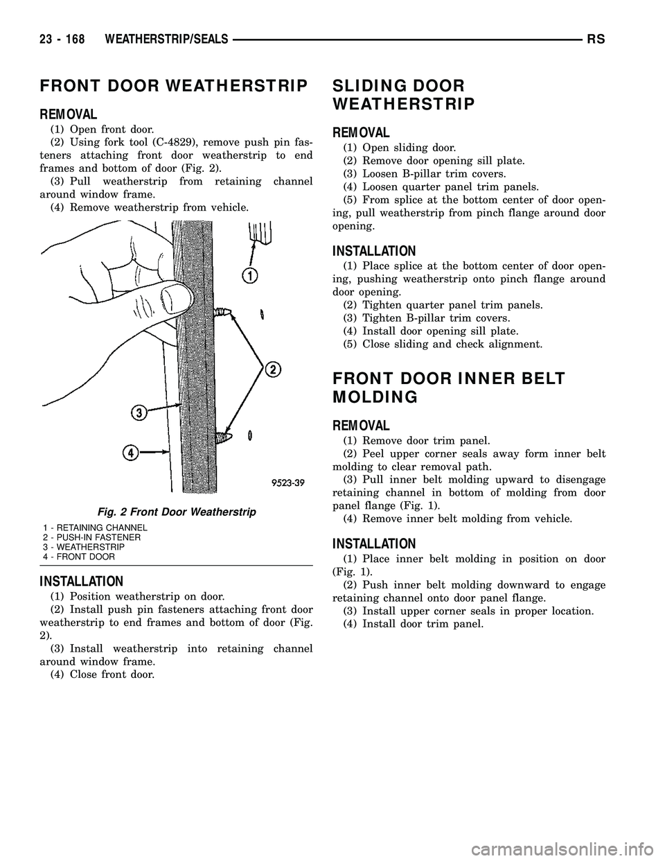
(2) Using fork tool (C-4829), remove push pin fas-
teners attaching front door weatherstrip to end
frames and bottom of door (Fig. 2).
(3) Pull weatherstrip from retaining channel
around window frame.
(4) Remove weatherstrip from vehicle.
INSTALLATION
(1) Position weatherstrip on door.
(2) Install push pin fasteners attaching front door
weatherstrip to end frames and bottom of door (Fig.
2).
(3) Install weatherstrip into retaining channel
around window frame.
(4) Close front door.
SLIDING DOOR
WEATHERSTRIP
REMOVAL
(1) Open sliding door.
(2) Remove door opening sill plate.
(3) Loosen B-pillar trim covers.
(4) Loosen quarter panel trim panels.
(5) From splice at the bottom center of door open-
ing, pull weatherstrip from pinch flange around door
opening.
INSTALLATION
(1) Place splice at the bottom center of door open-
ing, pushing weatherstrip onto pinch flange around
door opening.
(2) Tighten quarter panel trim panels.
(3) Tighten B-pillar trim covers.
(4) Install door opening sill plate.
(5) Close sliding and check alignment.
FRONT DOOR INNER BELT
MOLDING
REMOVAL
(1) Remove door trim panel.
(2) Peel upper corner seals away form inner belt
molding to clear removal path.
(3) Pull inner belt molding upward to disengage
retaining channel in bottom of molding from door
panel flange (Fig. 1).
(4) Remove inner belt molding from vehicle.
INSTALLATION
(1) Place inner belt molding in position on door
(Fig. 1).
(2) Push inner belt molding downward to engage
retaining channel onto door panel flange.
(3) Install upper corner seals in proper location.
(4) Install door trim panel.
Fig. 2 Front Door Weatherstrip
1 - RETAINING CHANNEL
2 - PUSH-IN FASTENER
3 - WEATHERSTRIP
4 - FRONT DOOR
23 - 168 WEATHERSTRIP/SEALSRS
Page 1951 of 2339
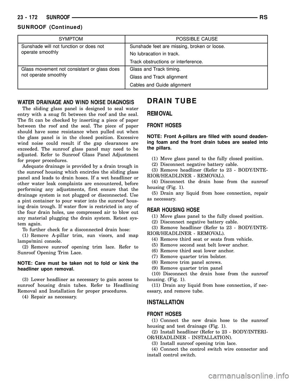
SYMPTOM POSSIBLE CAUSE
Sunshade will not function or does not
operate smoothlySunshade feet are missing, broken or loose.
No lubracation in track.
Track obstructions or interference.
Glass movement not consistant or glass does
not operate smoothlyGlass and Track timing.
Glass and Track alignment
Cables and Guide alignment
WATER DRAINAGE AND WIND NOISE DIAGNOSIS
The sliding glass panel is designed to seal water
entry with a snug fit between the roof and the seal.
The fit can be checked by inserting a piece of paper
between the roof and the seal. The piece of paper
should have some resistance when pulled out when
the glass panel is in the closed position. Excessive
wind noise could result if the gap clearances are
exceeded. The sunroof glass panel may need to be
adjusted. Refer to Sunroof Glass Panel Adjustment
for proper procedures.
Adequate drainage is provided by a drain trough in
the sunroof housing which encircles the sliding glass
panel and leads to drain hoses. If a wet headliner or
other water leak complaints are encountered, before
performing any adjustments, first ensure that the
drainage system is not plugged or disconnected. Use
a pint container to pour water into the sunroof hous-
ing drain trough. If water flow is restricted in any of
the four drain holes, use compressed air to blow out
any material plugging the drain system. Retest sys-
tem again.
To further check for a disconnected drain hose:
(1) Remove A-pillar trim, sun visors, and map
lamps/mini console.
(2) Remove sunroof opening trim lace. Refer to
Sunroof Opening Trim Lace.
NOTE: Care must be taken not to fold or kink the
headliner upon removal.
(3) Lower headliner as necessary to gain access to
sunroof housing drain tubes. Refer to Headlining
Removal and Installation for proper procedures.
(4) Repair as necessary.
DRAIN TUBE
REMOVAL
FRONT HOSES
NOTE: Front A-pillars are filled with sound deaden-
ing foam and the front drain tubes are sealed into
the pillars.
(1) Move glass panel to the fully closed position.
(2) Disconnect negative battery cable.
(3) Remove headliner (Refer to 23 - BODY/INTE-
RIOR/HEADLINER - REMOVAL).
(4) Disconnect the drain hose from the sunroof
housing (Fig. 1).
(5) Drain any liquid from hose connection, repair
as necessary.
REAR HOUSING HOSE
(1) Move glass panel to the fully closed position.
(2) Disconnect negative battery cable.
(3) Remove headliner (Refer to 23 - BODY/INTE-
RIOR/HEADLINER - REMOVAL).
(4) Remove third seat or seats from vehicle.
(5) Remove second seat belt lower anchor.
(6) Remove third seat lower anchor.
(7) Remove quarter trim bolster.
(8) Remove trim panel screws.
(9) Remove quarter trim panel
(10) Disconnect the drain hose from the sunroof
housing. (Fig. 1).
(11) Drain any liquid from hose connection, if nec-
essary, and remove tube.
INSTALLATION
FRONT HOSES
(1) Connect the new drain hose to the sunroof
housing and test drainage (Fig. 1).
(2) Install headliner (Refer to 23 - BODY/INTERI-
OR/HEADLINER - INSTALLATION).
(3) Install sunroof opening trim lace.
(4) Connect the control switch wire connector and
install control switch.
23 - 172 SUNROOFRS
SUNROOF (Continued)
Page 1963 of 2339
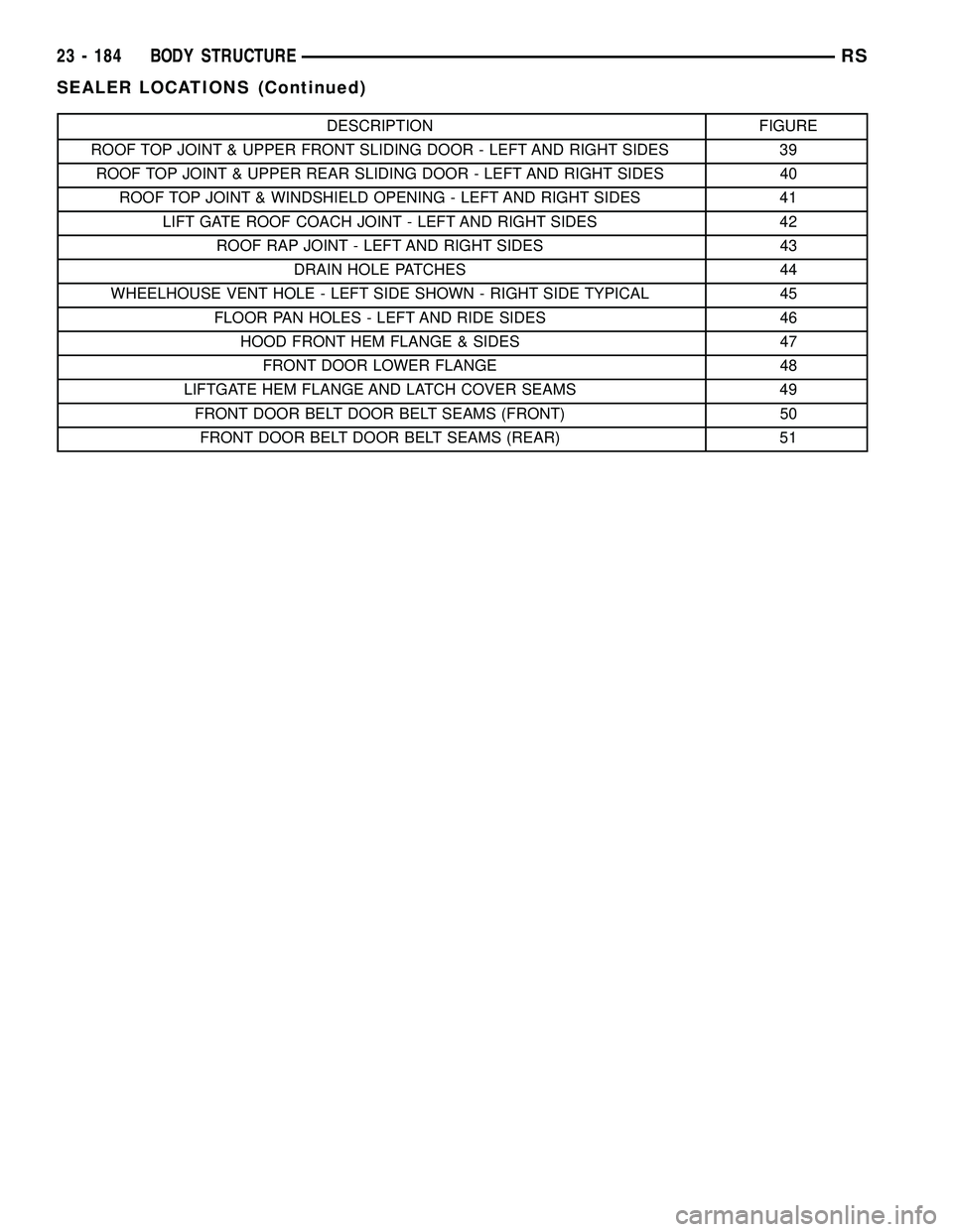
DESCRIPTION FIGURE
ROOF TOP JOINT & UPPER FRONT SLIDING DOOR - LEFT AND RIGHT SIDES 39
ROOF TOP JOINT & UPPER REAR SLIDING DOOR - LEFT AND RIGHT SIDES 40
ROOF TOP JOINT & WINDSHIELD OPENING - LEFT AND RIGHT SIDES 41
LIFT GATE ROOF COACH JOINT - LEFT AND RIGHT SIDES 42
ROOF RAP JOINT - LEFT AND RIGHT SIDES 43
DRAIN HOLE PATCHES 44
WHEELHOUSE VENT HOLE - LEFT SIDE SHOWN - RIGHT SIDE TYPICAL 45
FLOOR PAN HOLES - LEFT AND RIDE SIDES 46
HOOD FRONT HEM FLANGE & SIDES 47
FRONT DOOR LOWER FLANGE 48
LIFTGATE HEM FLANGE AND LATCH COVER SEAMS 49
FRONT DOOR BELT DOOR BELT SEAMS (FRONT) 50
FRONT DOOR BELT DOOR BELT SEAMS (REAR) 51
23 - 184 BODY STRUCTURERS
SEALER LOCATIONS (Continued)
Page 1987 of 2339
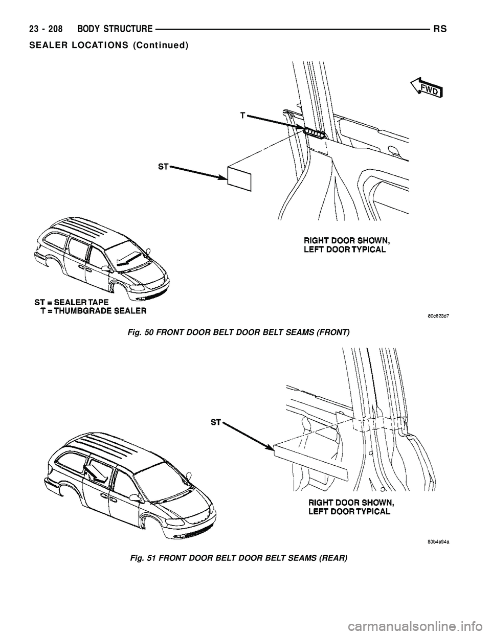
Fig. 50 FRONT DOOR BELT DOOR BELT SEAMS (FRONT)
Fig. 51 FRONT DOOR BELT DOOR BELT SEAMS (REAR)
23 - 208 BODY STRUCTURERS
SEALER LOCATIONS (Continued)