2005 CHRYSLER CARAVAN belt
[x] Cancel search: beltPage 2014 of 2339
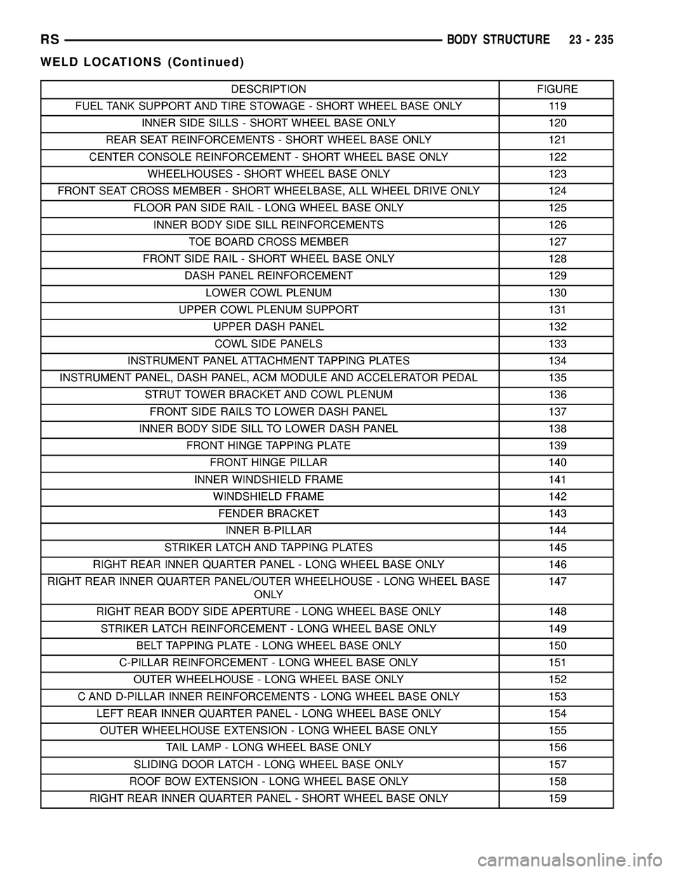
DESCRIPTION FIGURE
FUEL TANK SUPPORT AND TIRE STOWAGE - SHORT WHEEL BASE ONLY 119
INNER SIDE SILLS - SHORT WHEEL BASE ONLY 120
REAR SEAT REINFORCEMENTS - SHORT WHEEL BASE ONLY 121
CENTER CONSOLE REINFORCEMENT - SHORT WHEEL BASE ONLY 122
WHEELHOUSES - SHORT WHEEL BASE ONLY 123
FRONT SEAT CROSS MEMBER - SHORT WHEELBASE, ALL WHEEL DRIVE ONLY 124
FLOOR PAN SIDE RAIL - LONG WHEEL BASE ONLY 125
INNER BODY SIDE SILL REINFORCEMENTS 126
TOE BOARD CROSS MEMBER 127
FRONT SIDE RAIL - SHORT WHEEL BASE ONLY 128
DASH PANEL REINFORCEMENT 129
LOWER COWL PLENUM 130
UPPER COWL PLENUM SUPPORT 131
UPPER DASH PANEL 132
COWL SIDE PANELS 133
INSTRUMENT PANEL ATTACHMENT TAPPING PLATES 134
INSTRUMENT PANEL, DASH PANEL, ACM MODULE AND ACCELERATOR PEDAL 135
STRUT TOWER BRACKET AND COWL PLENUM 136
FRONT SIDE RAILS TO LOWER DASH PANEL 137
INNER BODY SIDE SILL TO LOWER DASH PANEL 138
FRONT HINGE TAPPING PLATE 139
FRONT HINGE PILLAR 140
INNER WINDSHIELD FRAME 141
WINDSHIELD FRAME 142
FENDER BRACKET 143
INNER B-PILLAR 144
STRIKER LATCH AND TAPPING PLATES 145
RIGHT REAR INNER QUARTER PANEL - LONG WHEEL BASE ONLY 146
RIGHT REAR INNER QUARTER PANEL/OUTER WHEELHOUSE - LONG WHEEL BASE
ONLY147
RIGHT REAR BODY SIDE APERTURE - LONG WHEEL BASE ONLY 148
STRIKER LATCH REINFORCEMENT - LONG WHEEL BASE ONLY 149
BELT TAPPING PLATE - LONG WHEEL BASE ONLY 150
C-PILLAR REINFORCEMENT - LONG WHEEL BASE ONLY 151
OUTER WHEELHOUSE - LONG WHEEL BASE ONLY 152
C AND D-PILLAR INNER REINFORCEMENTS - LONG WHEEL BASE ONLY 153
LEFT REAR INNER QUARTER PANEL - LONG WHEEL BASE ONLY 154
OUTER WHEELHOUSE EXTENSION - LONG WHEEL BASE ONLY 155
TAIL LAMP - LONG WHEEL BASE ONLY 156
SLIDING DOOR LATCH - LONG WHEEL BASE ONLY 157
ROOF BOW EXTENSION - LONG WHEEL BASE ONLY 158
RIGHT REAR INNER QUARTER PANEL - SHORT WHEEL BASE ONLY 159
RSBODY STRUCTURE23 - 235
WELD LOCATIONS (Continued)
Page 2016 of 2339
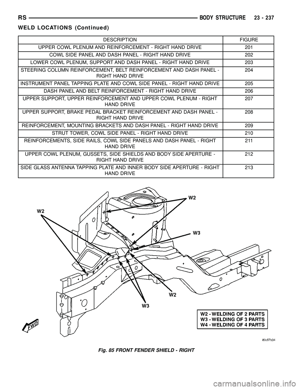
DESCRIPTION FIGURE
UPPER COWL PLENUM AND REINFORCEMENT - RIGHT HAND DRIVE 201
COWL SIDE PANEL AND DASH PANEL - RIGHT HAND DRIVE 202
LOWER COWL PLENUM, SUPPORT AND DASH PANEL - RIGHT HAND DRIVE 203
STEERING COLUMN REINFORCEMENT, BELT REINFORCEMENT AND DASH PANEL -
RIGHT HAND DRIVE204
INSTRUMENT PANEL TAPPING PLATE AND COWL SIDE PANEL - RIGHT HAND DRIVE 205
DASH PANEL AND BELT REINFORCEMENT - RIGHT HAND DRIVE 206
UPPER SUPPORT, UPPER REINFORCEMENT AND UPPER COWL PLENUM - RIGHT
HAND DRIVE207
UPPER SUPPORT, BRAKE PEDAL BRACKET REINFORCEMENT AND DASH PANEL -
RIGHT HAND DRIVE208
REINFORCEMENT, MOUNTING BRACKETS AND DASH PANEL - RIGHT HAND DRIVE 209
STRUT TOWER, COWL SIDE PANEL - RIGHT HAND DRIVE 210
REINFORCEMENTS, SIDE RAILS, COWL SIDE PANELS AND DASH PANEL - RIGHT
HAND DRIVE211
UPPER COWL PLENUM, GUSSETS, SIDE SHIELDS AND BODY SIDE APERTURE -
RIGHT HAND DRIVE212
SIDE GLASS ANTENNA TAPPING PLATE AND INNER BODY SIDE APERTURE - RIGHT
HAND DRIVE213
Fig. 85 FRONT FENDER SHIELD - RIGHT
RSBODY STRUCTURE23 - 237
WELD LOCATIONS (Continued)
Page 2073 of 2339
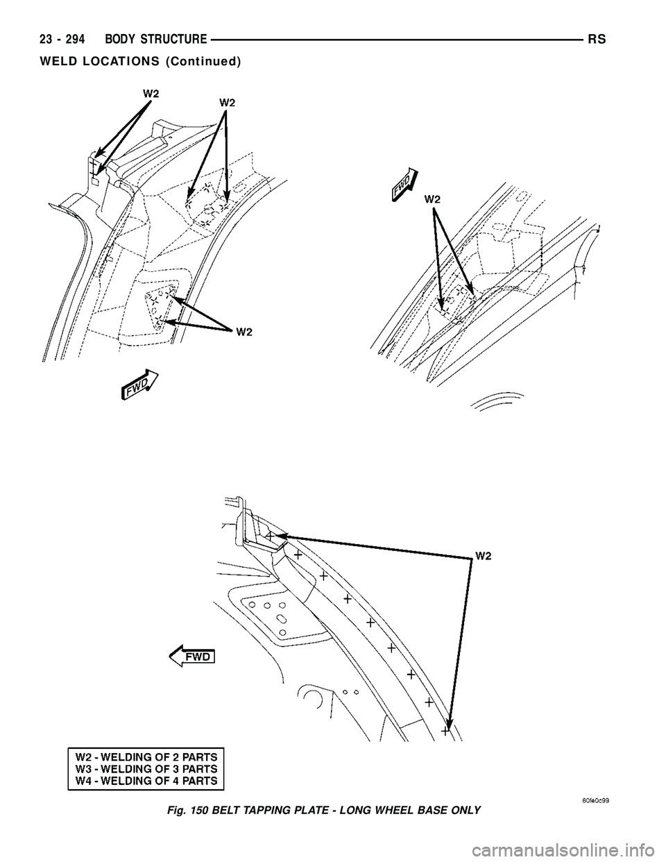
Fig. 150 BELT TAPPING PLATE - LONG WHEEL BASE ONLY
23 - 294 BODY STRUCTURERS
WELD LOCATIONS (Continued)
Page 2120 of 2339
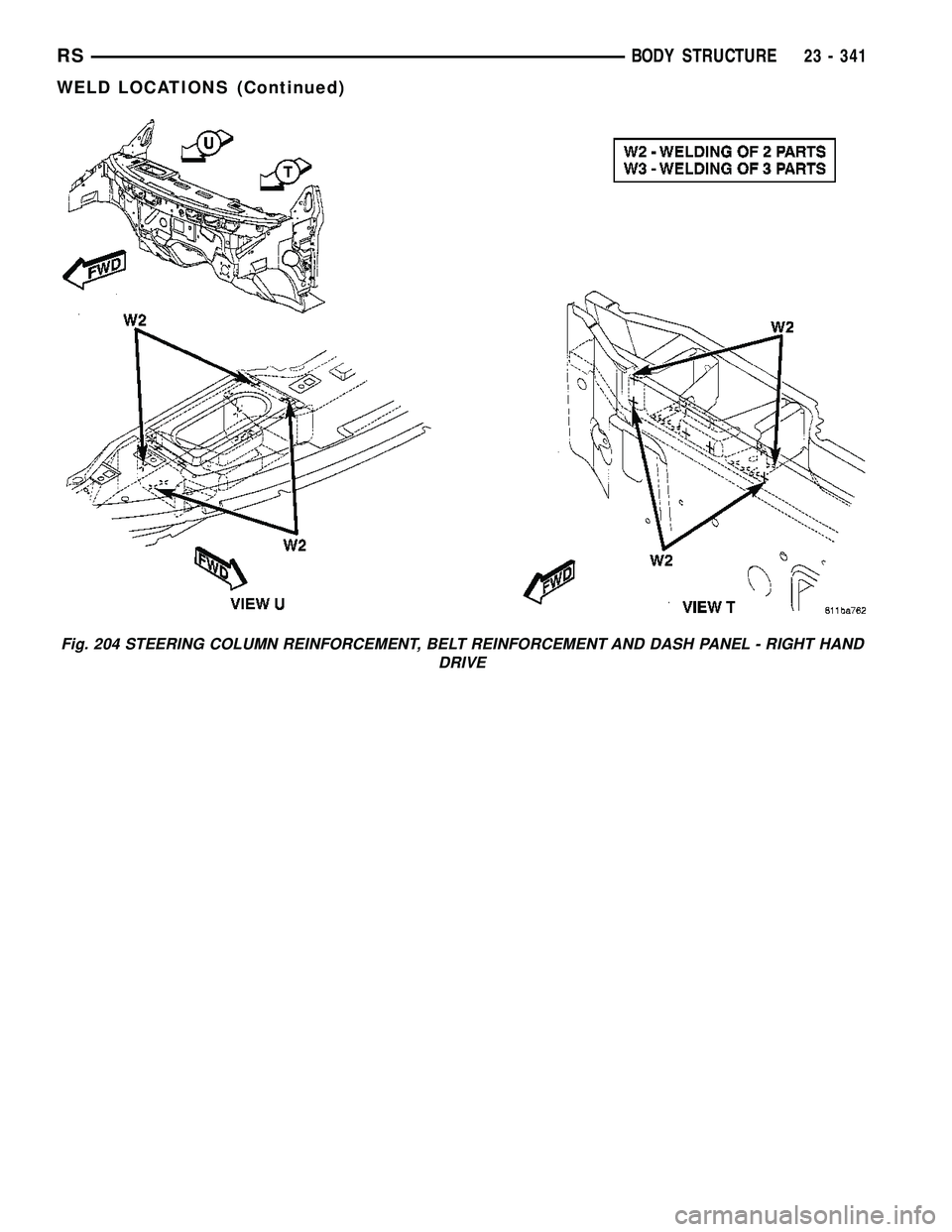
Fig. 204 STEERING COLUMN REINFORCEMENT, BELT REINFORCEMENT AND DASH PANEL - RIGHT HAND
DRIVE
RSBODY STRUCTURE23 - 341
WELD LOCATIONS (Continued)
Page 2122 of 2339
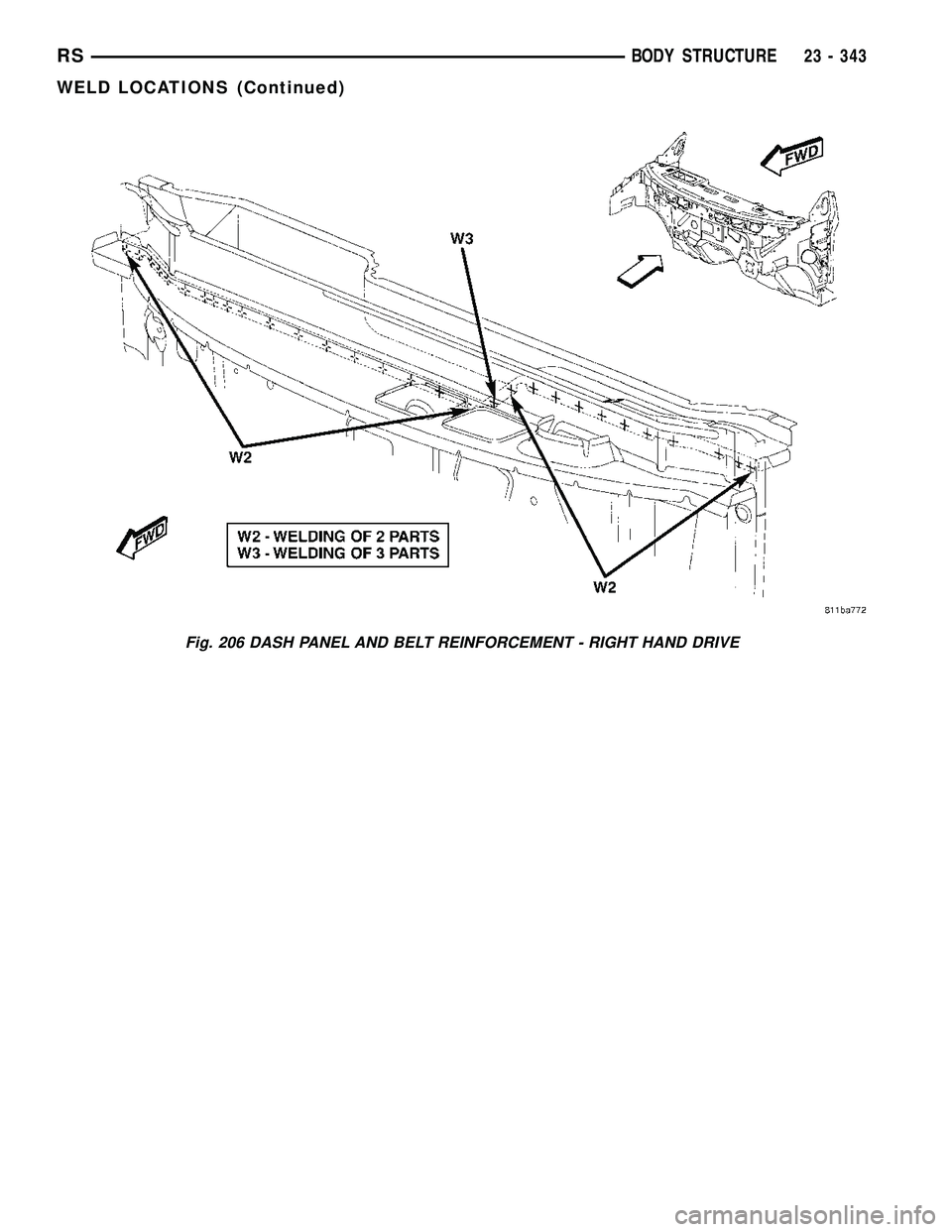
Fig. 206 DASH PANEL AND BELT REINFORCEMENT - RIGHT HAND DRIVE
RSBODY STRUCTURE23 - 343
WELD LOCATIONS (Continued)
Page 2160 of 2339
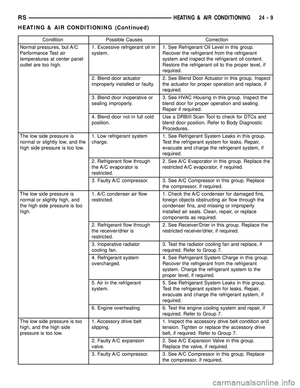
Condition Possible Causes Correction
Normal pressures, but A/C
Performance Test air
temperatures at center panel
outlet are too high.1. Excessive refrigerant oil in
system.1. See Refrigerant Oil Level in this group.
Recover the refrigerant from the refrigerant
system and inspect the refrigerant oil content.
Restore the refrigerant oil to the proper level, if
required.
2. Blend door actuator
improperly installed or faulty.2. See Blend Door Actuator in this group. Inspect
the actuator for proper operation and replace, if
required.
3. Blend door inoperative or
sealing improperly.3. See HVAC Housing in this group. Inspect the
blend door for proper operation and sealing.
Repair if required.
4. Blend door not in full cold
position.Use a DRBIII Scan Tool to check for DTCs and
blend door position. Refer to Body Diagnostic
Procedures.
The low side pressure is
normal or slightly low, and the
high side pressure is too low.1. Low refrigerant system
charge.1. See Refrigerant System Leaks in this group.
Test the refrigerant system for leaks. Repair,
evacuate and charge the refrigerant system, if
required.
2. Refrigerant flow through
the A/C evaporator is
restricted.2. See A/C Evaporator in this group. Replace the
restricted A/C evaporator, if required.
3. Faulty A/C compressor. 3. See A/C Compressor in this group. Replace
the compressor, if required.
The low side pressure is
normal or slightly high, and
the high side pressure is too
high.1. A/C condenser air flow
restricted.1. Check the A/C condenser for damaged fins,
foreign objects obstructing air flow through the
condenser fins, and missing or improperly
installed air seals. Clean, repair, or replace
components as required.
2. Refrigerant flow through
the receiver/drier is
restricted.2. See Receiver/Drier in this group. Replace the
restricted receiver/drier, if required.
3. Inoperative radiator
cooling fan.3. Test the radiator cooling fan and replace, if
required. Refer to Group 7.
4. Refrigerant system
overcharged.4. See Refrigerant System Charge in this group.
Recover the refrigerant from the refrigerant
system. Charge the refrigerant system to the
proper level, if required.
5. Air in the refrigerant
system.5. See Refrigerant System Leaks in this group.
Test the refrigerant system for leaks. Repair,
evacuate and charge the refrigerant system, if
required.
6. Engine overheating. 6. Test the engine cooling system and repair, if
required. Refer to Group 7.
The low side pressure is too
high, and the high side
pressure is too low.1. Accessory drive belt
slipping.1. Inspect the accessory drive belt condition and
tension. Tighten or replace the accessory drive
belt, if required. Refer to Group 7.
2. Faulty A/C expansion
valve.2. See A/C Expansion Valve in this group.
Replace the valve, if required.
3. Faulty A/C compressor. 3. See A/C Compressor in this group. Replace
the compressor, if required.
RSHEATING & AIR CONDITIONING24-9
HEATING & AIR CONDITIONING (Continued)
Page 2161 of 2339
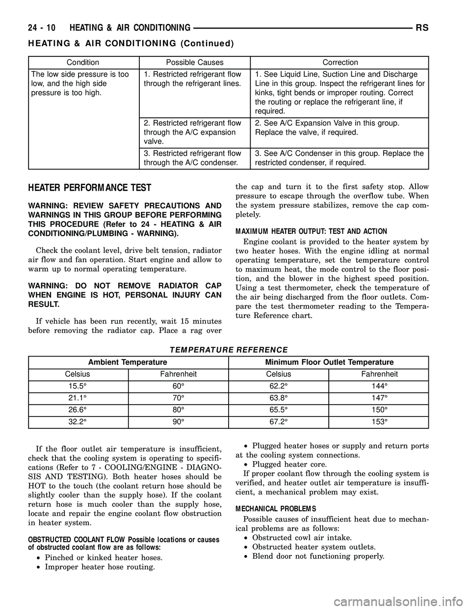
Condition Possible Causes Correction
The low side pressure is too
low, and the high side
pressure is too high.1. Restricted refrigerant flow
through the refrigerant lines.1. See Liquid Line, Suction Line and Discharge
Line in this group. Inspect the refrigerant lines for
kinks, tight bends or improper routing. Correct
the routing or replace the refrigerant line, if
required.
2. Restricted refrigerant flow
through the A/C expansion
valve.2. See A/C Expansion Valve in this group.
Replace the valve, if required.
3. Restricted refrigerant flow
through the A/C condenser.3. See A/C Condenser in this group. Replace the
restricted condenser, if required.
HEATER PERFORMANCE TEST
WARNING: REVIEW SAFETY PRECAUTIONS AND
WARNINGS IN THIS GROUP BEFORE PERFORMING
THIS PROCEDURE (Refer to 24 - HEATING & AIR
CONDITIONING/PLUMBING - WARNING).
Check the coolant level, drive belt tension, radiator
air flow and fan operation. Start engine and allow to
warm up to normal operating temperature.
WARNING: DO NOT REMOVE RADIATOR CAP
WHEN ENGINE IS HOT, PERSONAL INJURY CAN
RESULT.
If vehicle has been run recently, wait 15 minutes
before removing the radiator cap. Place a rag overthe cap and turn it to the first safety stop. Allow
pressure to escape through the overflow tube. When
the system pressure stabilizes, remove the cap com-
pletely.
MAXIMUM HEATER OUTPUT: TEST AND ACTION
Engine coolant is provided to the heater system by
two heater hoses. With the engine idling at normal
operating temperature, set the temperature control
to maximum heat, the mode control to the floor posi-
tion, and the blower in the highest speed position.
Using a test thermometer, check the temperature of
the air being discharged from the floor outlets. Com-
pare the test thermometer reading to the Tempera-
ture Reference chart.
TEMPERATURE REFERENCE
Ambient Temperature Minimum Floor Outlet Temperature
Celsius Fahrenheit Celsius Fahrenheit
15.5É 60É 62.2É 144É
21.1É 70É 63.8É 147É
26.6É 80É 65.5É 150É
32.2É 90É 67.2É 153É
If the floor outlet air temperature is insufficient,
check that the cooling system is operating to specifi-
cations (Refer to 7 - COOLING/ENGINE - DIAGNO-
SIS AND TESTING). Both heater hoses should be
HOT to the touch (the coolant return hose should be
slightly cooler than the supply hose). If the coolant
return hose is much cooler than the supply hose,
locate and repair the engine coolant flow obstruction
in heater system.
OBSTRUCTED COOLANT FLOW Possible locations or causes
of obstructed coolant flow are as follows:
²Pinched or kinked heater hoses.
²Improper heater hose routing.²Plugged heater hoses or supply and return ports
at the cooling system connections.
²Plugged heater core.
If proper coolant flow through the cooling system is
verified, and heater outlet air temperature is insuffi-
cient, a mechanical problem may exist.
MECHANICAL PROBLEMS
Possible causes of insufficient heat due to mechan-
ical problems are as follows:
²Obstructed cowl air intake.
²Obstructed heater system outlets.
²Blend door not functioning properly.
24 - 10 HEATING & AIR CONDITIONINGRS
HEATING & AIR CONDITIONING (Continued)
Page 2164 of 2339
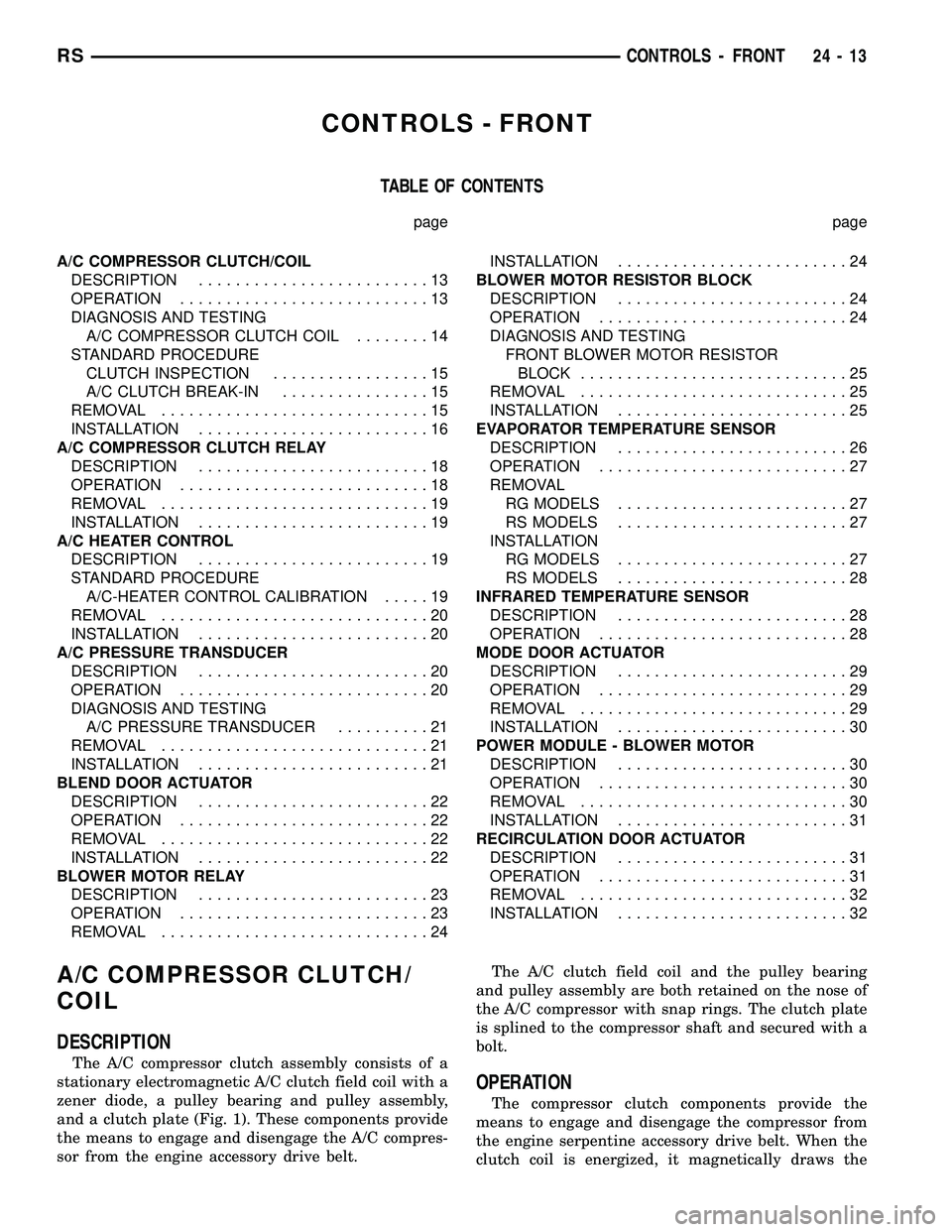
CONTROLS - FRONT
TABLE OF CONTENTS
page page
A/C COMPRESSOR CLUTCH/COIL
DESCRIPTION.........................13
OPERATION...........................13
DIAGNOSIS AND TESTING
A/C COMPRESSOR CLUTCH COIL........14
STANDARD PROCEDURE
CLUTCH INSPECTION.................15
A/C CLUTCH BREAK-IN................15
REMOVAL.............................15
INSTALLATION.........................16
A/C COMPRESSOR CLUTCH RELAY
DESCRIPTION.........................18
OPERATION...........................18
REMOVAL.............................19
INSTALLATION.........................19
A/C HEATER CONTROL
DESCRIPTION.........................19
STANDARD PROCEDURE
A/C-HEATER CONTROL CALIBRATION.....19
REMOVAL.............................20
INSTALLATION.........................20
A/C PRESSURE TRANSDUCER
DESCRIPTION.........................20
OPERATION...........................20
DIAGNOSIS AND TESTING
A/C PRESSURE TRANSDUCER..........21
REMOVAL.............................21
INSTALLATION.........................21
BLEND DOOR ACTUATOR
DESCRIPTION.........................22
OPERATION...........................22
REMOVAL.............................22
INSTALLATION.........................22
BLOWER MOTOR RELAY
DESCRIPTION.........................23
OPERATION...........................23
REMOVAL.............................24INSTALLATION.........................24
BLOWER MOTOR RESISTOR BLOCK
DESCRIPTION.........................24
OPERATION...........................24
DIAGNOSIS AND TESTING
FRONT BLOWER MOTOR RESISTOR
BLOCK.............................25
REMOVAL.............................25
INSTALLATION.........................25
EVAPORATOR TEMPERATURE SENSOR
DESCRIPTION.........................26
OPERATION...........................27
REMOVAL
RG MODELS.........................27
RS MODELS.........................27
INSTALLATION
RG MODELS.........................27
RS MODELS.........................28
INFRARED TEMPERATURE SENSOR
DESCRIPTION.........................28
OPERATION...........................28
MODE DOOR ACTUATOR
DESCRIPTION.........................29
OPERATION...........................29
REMOVAL.............................29
INSTALLATION.........................30
POWER MODULE - BLOWER MOTOR
DESCRIPTION.........................30
OPERATION...........................30
REMOVAL.............................30
INSTALLATION.........................31
RECIRCULATION DOOR ACTUATOR
DESCRIPTION.........................31
OPERATION...........................31
REMOVAL.............................32
INSTALLATION.........................32
A/C COMPRESSOR CLUTCH/
COIL
DESCRIPTION
The A/C compressor clutch assembly consists of a
stationary electromagnetic A/C clutch field coil with a
zener diode, a pulley bearing and pulley assembly,
and a clutch plate (Fig. 1). These components provide
the means to engage and disengage the A/C compres-
sor from the engine accessory drive belt.The A/C clutch field coil and the pulley bearing
and pulley assembly are both retained on the nose of
the A/C compressor with snap rings. The clutch plate
is splined to the compressor shaft and secured with a
bolt.
OPERATION
The compressor clutch components provide the
means to engage and disengage the compressor from
the engine serpentine accessory drive belt. When the
clutch coil is energized, it magnetically draws the
RSCONTROLS - FRONT24-13