2005 CHRYSLER CARAVAN engine oil capacity
[x] Cancel search: engine oil capacityPage 246 of 2339

INSTALLATION
(1)Be sure the air seal is in position before
radiator is installed.Slide radiator down into posi-
tion. Seat the radiator with the rubber isolators into
the mounting holes provided, with a 10 lbs. force.
(2) Position air conditioning condenser onto the
radiator lower mounts and ingage upper mounting
tabs. (Fig. 15).
(3) Install the radiator upper and lower hoses (Fig.
13) or (Fig. 14).
(4) Connect the coolant reserve/recovery hose.
(5) Connect the vapor purge solenoid to the mount-
ing bracket.
(6) Install the radiator fans. (Refer to 7 - COOL-
ING/ENGINE/RADIATOR FAN - INSTALLATION)
(7) Install the radiator upper crossmember sup-
port. (Refer to 23 - BODY/EXTERIOR/GRILLE
OPENING REINFORCEMENT - INSTALLATION)
(8) Fill the cooling system. (Refer to 7 - COOLING
- STANDARD PROCEDURE)
(9) Connect negative cable to battery.
RADIATOR DRAINCOCK
REMOVAL
NOTE: It is not necessary to remove draincock dur-
ing a routine coolant drain.
(1) Drain the cooling system. (Refer to 7 - COOL-
ING - STANDARD PROCEDURE)
(2) Using a screwdriver, open the draincock by
turning it counterclockwise until it stops.
(3) Pull the draincock from the radiator tank.
INSTALLATION
(1) Align draincock stem to radiator tank opening.
(2) Push draincock into the radiator tank opening.
CAUTION: Do not overtighten. The head of the
draincock may break off.
(3) Using a screwdriver, tighten the draincock by
turning clockwise until it stops.
(4) Fill the cooling system. (Refer to 7 - COOLING
- STANDARD PROCEDURE)
RADIATOR PRESSURE CAP
DESCRIPTION
The cooling system pressure cap is located on the
radiator. The cap construction includes; stainless
steel swivel top, rubber seals, and retainer, main
spring, and a spring loaded valve (Fig. 16).
OPERATION
The cooling system is equipped with a pressure cap
that releases excessive pressure; maintaining a range
of 97-124 kPa (14-18 psi).
The cooling system will operate at higher than
atmospheric pressure. The higher pressure raises the
coolant boiling point thus, allowing increased radia-
tor cooling capacity.
There is also a vent valve in the center of the cap.
This valve also opens when coolant is cooling and
contracting, allowing the coolant to return to cooling
system from coolant reserve system tank by vacuum
through a connecting hose.If valve is stuck shut,
or the coolant recovery hose is pinched, the
radiator hoses will be collapsed on cool down.
Clean the vent valve (Fig. 16) and inspect cool-
ant recovery hose routing, to ensure proper
sealing when boiling point is reached.
The gasket in the cap seals the filler neck, so that
vacuum can be maintained, allowing coolant to be
drawn back into the radiator from the reserve tank.
If the gasket is dirty or damaged, a vacuum
may not be achieved, resulting is loss of coolant
and eventual overheating due to low coolant
level in radiator and engine.
Fig. 16 Cooling System Pressure Cap Filler Neck
1 - OVERFLOW NIPPLE
2 - MAIN SPRING
3 - GASKET RETAINER
4 - STAINLESS-STEEL SWIVEL TOP
5 - RUBBER SEALS
6 - VENT VALVE
7 - RADIATOR
8 - FILLER NECK
RSENGINE7-27
RADIATOR (Continued)
Page 2158 of 2339
rator initial temperature, then the cool down test has
been failed and further A/C system diagnosis is
required. If the test is failed, the snowflake icon and
the DELAY text will continue to blink across ignition
cycles until the vehicle has been driven for greater
than 13 km (8 miles).
A/C PERFORMANCE TEST
The A/C system is designed to remove heat and
humidity from the air entering the passenger com-
partment. The evaporator, located in the HVAC hous-
ing, is cooled to temperatures near the freezing point.
As warm damp air passes over the fins in the A/C
evaporator, moisture in the air condenses to water,
dehumidifying the air. Condensation on the evapora-
tor fins reduces the evaporators ability to absorb
heat. During periods of high heat and humidity, an
A/C system will be less effective. With the instru-
ment control set to recirculation mode, only air from
the passenger compartment passes through the A/C
evaporator. As the passenger compartment air dehu-
midifies, A/C performance levels rise.
Humidity has an important bearing on the temper-
ature of the air delivered to the interior of the vehi-
cle. It is important to understand the effect that
humidity has on the performance of the A/C system.
When humidity is high, the A/C evaporator has to
perform a double duty. It must lower the air temper-
ature, and it must lower the temperature of the
moisture in the air that condenses on the evaporator
fins. Condensing the moisture in the air transfers
heat energy into the evaporator fins and tubing. This
reduces the amount of heat the A/C evaporator can
absorb from the air. High humidity greatly reduces
the ability of the A/C evaporator to lower the temper-
ature of the air.
However, evaporator capacity used to reduce the
amount of moisture in the air is not wasted. Wring-
ing some of the moisture out of the air entering the
vehicle adds to the comfort of the passengers.
Although, an owner may expect too much from their
A/C system on humid days. A performance test is the
best way to determine whether the system is per-
forming up to design standards. This test also pro-
vides valuable clues as to the possible cause of
trouble with the A/C system. The ambient air tem-perature in the location where the vehicle will be
tested must be a minimum of 21É C (70É F) for this
test.
PERFORMANCE TEST PROCEDURE
WARNING: REFER TO THE APPLICABLE WARN-
INGS AND CAUTIONS FOR THIS SYSTEM BEFORE
PERFORMING THE FOLLOWING OPERATION (Refer
to 24 - HEATING & AIR CONDITIONING/PLUMBING -
FRONT - WARNING - A/C PLUMBING) and (Refer to
24 - HEATING & AIR CONDITIONING/PLUMBING -
FRONT - CAUTION - A/C PLUMBING).
NOTE: When connecting the service equipment
coupling to the line fitting, verify that the valve of
the coupling is fully closed. This will reduce the
amount of effort required to make the connection.
(1) Connect a tachometer and a manifold gauge
set.
(2) Set the mode control to the Recirculation Mode
position, the temperature control to the full cool posi-
tion and the blower to the highest speed position.
(3) Start the engine and hold at 1,000 rpm with
the A/C compressor clutch engaged.
(4) The engine should be warmed up to operating
temperature with the doors closed and windows
open.
(5) Insert a thermometer in the driver's side center
panel A/C-heater outlet and operate the engine for
five minutes.
(6) If the compressor clutch does not engage, pro-
ceed with diagnosis of the compressor clutch coil.
(Refer to 24 - HEATING & AIR CONDITIONING/
CONTROLS - FRONT/COMPRESSOR CLUTCH
COIL - DIAGNOSIS AND TESTING).
(7) With the A/C compressor clutch engaged, com-
pare the air temperature at the center panel outlet
and the compressor discharge pressure to the A/C
Performance Temperature and Pressure chart. The
compressor clutch may cycle, depending upon the
ambient temperature and humidity. If the clutch
cycles, use the readings obtained before the clutch
disengaged.
RSHEATING & AIR CONDITIONING24-7
HEATING & AIR CONDITIONING (Continued)
Page 2162 of 2339
TEMPERATURE CONTROL
If the heater outlet air temperature cannot be
adjusted with the temperature control knob on the
A/C-heater control panel, the following could require
service:
²Blend door binding.
²Faulty blend door actuator.
²Faulty A/C-heater control.
²Faulty related wiring harness or connectors.²Improper engine coolant temperature.
SPECIFICATIONS
A/C SYSTEM
The R-134a refrigerant system charge capacity for
this vehicle can be found on the underhood Specifica-
tion Label.
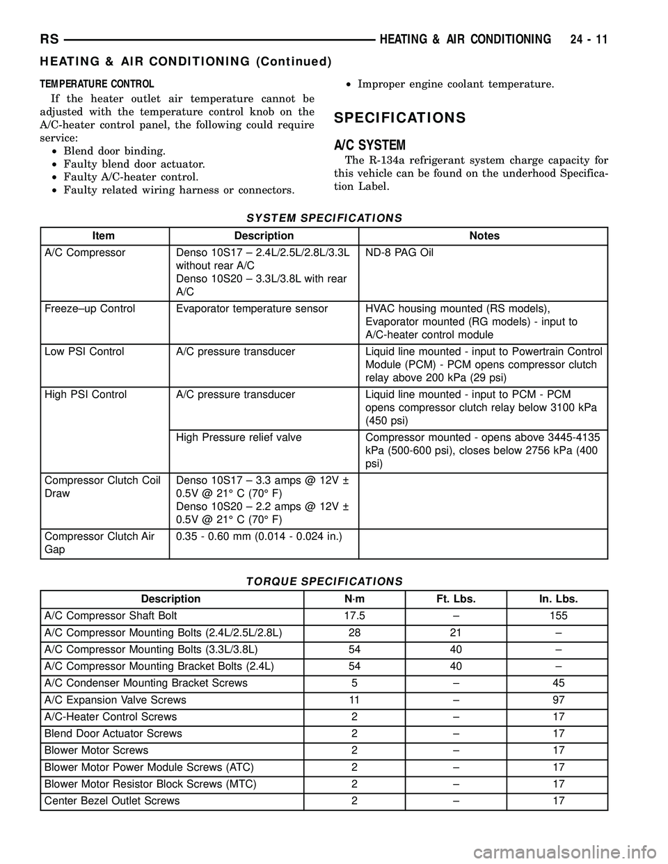
SYSTEM SPECIFICATIONS
Item Description Notes
A/C Compressor Denso 10S17 ± 2.4L/2.5L/2.8L/3.3L
without rear A/C
Denso 10S20 ± 3.3L/3.8L with rear
A/CND-8 PAG Oil
Freeze±up Control Evaporator temperature sensor HVAC housing mounted (RS models),
Evaporator mounted (RG models) - input to
A/C-heater control module
Low PSI Control A/C pressure transducer Liquid line mounted - input to Powertrain Control
Module (PCM) - PCM opens compressor clutch
relay above 200 kPa (29 psi)
High PSI Control A/C pressure transducer Liquid line mounted - input to PCM - PCM
opens compressor clutch relay below 3100 kPa
(450 psi)
High Pressure relief valve Compressor mounted - opens above 3445-4135
kPa (500-600 psi), closes below 2756 kPa (400
psi)
Compressor Clutch Coil
DrawDenso 10S17 ± 3.3 amps @ 12V
0.5V @ 21É C (70É F)
Denso 10S20 ± 2.2 amps @ 12V
0.5V @ 21É C (70É F)
Compressor Clutch Air
Gap0.35 - 0.60 mm (0.014 - 0.024 in.)
TORQUE SPECIFICATIONS
Description N´m Ft. Lbs. In. Lbs.
A/C Compressor Shaft Bolt 17.5 ± 155
A/C Compressor Mounting Bolts (2.4L/2.5L/2.8L) 28 21 ±
A/C Compressor Mounting Bolts (3.3L/3.8L) 54 40 ±
A/C Compressor Mounting Bracket Bolts (2.4L) 54 40 ±
A/C Condenser Mounting Bracket Screws 5 ± 45
A/C Expansion Valve Screws 11 ± 97
A/C-Heater Control Screws 2 ± 17
Blend Door Actuator Screws 2 ± 17
Blower Motor Screws 2 ± 17
Blower Motor Power Module Screws (ATC) 2 ± 17
Blower Motor Resistor Block Screws (MTC) 2 ± 17
Center Bezel Outlet Screws 2 ± 17
RSHEATING & AIR CONDITIONING24-11
HEATING & AIR CONDITIONING (Continued)
Page 2169 of 2339
A/C COMPRESSOR CLUTCH
RELAY
DESCRIPTION
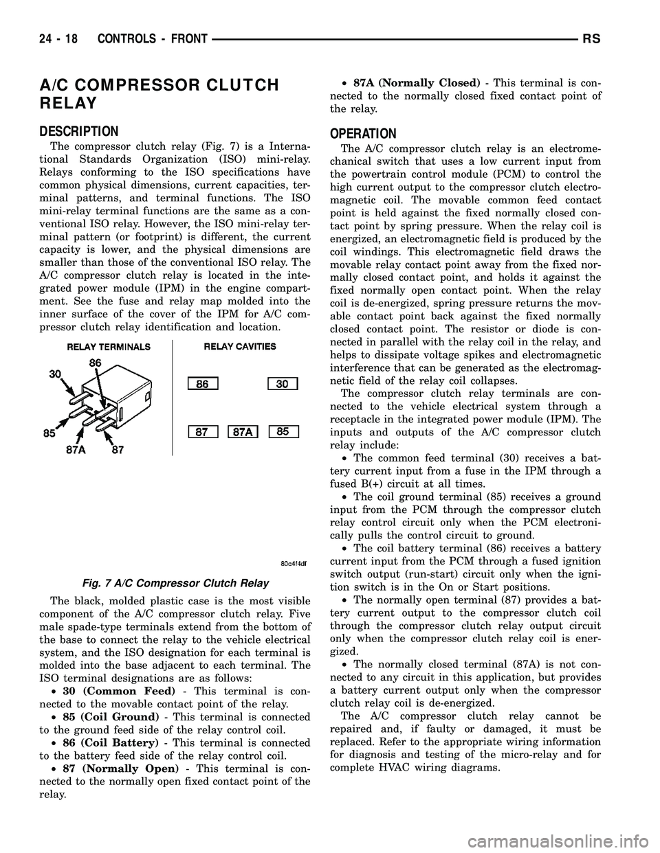
The compressor clutch relay (Fig. 7) is a Interna-
tional Standards Organization (ISO) mini-relay.
Relays conforming to the ISO specifications have
common physical dimensions, current capacities, ter-
minal patterns, and terminal functions. The ISO
mini-relay terminal functions are the same as a con-
ventional ISO relay. However, the ISO mini-relay ter-
minal pattern (or footprint) is different, the current
capacity is lower, and the physical dimensions are
smaller than those of the conventional ISO relay. The
A/C compressor clutch relay is located in the inte-
grated power module (IPM) in the engine compart-
ment. See the fuse and relay map molded into the
inner surface of the cover of the IPM for A/C com-
pressor clutch relay identification and location.
The black, molded plastic case is the most visible
component of the A/C compressor clutch relay. Five
male spade-type terminals extend from the bottom of
the base to connect the relay to the vehicle electrical
system, and the ISO designation for each terminal is
molded into the base adjacent to each terminal. The
ISO terminal designations are as follows:
²30 (Common Feed)- This terminal is con-
nected to the movable contact point of the relay.
²85 (Coil Ground)- This terminal is connected
to the ground feed side of the relay control coil.
²86 (Coil Battery)- This terminal is connected
to the battery feed side of the relay control coil.
²87 (Normally Open)- This terminal is con-
nected to the normally open fixed contact point of the
relay.²87A (Normally Closed)- This terminal is con-
nected to the normally closed fixed contact point of
the relay.
OPERATION
The A/C compressor clutch relay is an electrome-
chanical switch that uses a low current input from
the powertrain control module (PCM) to control the
high current output to the compressor clutch electro-
magnetic coil. The movable common feed contact
point is held against the fixed normally closed con-
tact point by spring pressure. When the relay coil is
energized, an electromagnetic field is produced by the
coil windings. This electromagnetic field draws the
movable relay contact point away from the fixed nor-
mally closed contact point, and holds it against the
fixed normally open contact point. When the relay
coil is de-energized, spring pressure returns the mov-
able contact point back against the fixed normally
closed contact point. The resistor or diode is con-
nected in parallel with the relay coil in the relay, and
helps to dissipate voltage spikes and electromagnetic
interference that can be generated as the electromag-
netic field of the relay coil collapses.
The compressor clutch relay terminals are con-
nected to the vehicle electrical system through a
receptacle in the integrated power module (IPM). The
inputs and outputs of the A/C compressor clutch
relay include:
²The common feed terminal (30) receives a bat-
tery current input from a fuse in the IPM through a
fused B(+) circuit at all times.
²The coil ground terminal (85) receives a ground
input from the PCM through the compressor clutch
relay control circuit only when the PCM electroni-
cally pulls the control circuit to ground.
²The coil battery terminal (86) receives a battery
current input from the PCM through a fused ignition
switch output (run-start) circuit only when the igni-
tion switch is in the On or Start positions.
²The normally open terminal (87) provides a bat-
tery current output to the compressor clutch coil
through the compressor clutch relay output circuit
only when the compressor clutch relay coil is ener-
gized.
²The normally closed terminal (87A) is not con-
nected to any circuit in this application, but provides
a battery current output only when the compressor
clutch relay coil is de-energized.
The A/C compressor clutch relay cannot be
repaired and, if faulty or damaged, it must be
replaced. Refer to the appropriate wiring information
for diagnosis and testing of the micro-relay and for
complete HVAC wiring diagrams.
Fig. 7 A/C Compressor Clutch Relay
24 - 18 CONTROLS - FRONTRS
Page 2216 of 2339
PLUMBING - FRONT
DESCRIPTION
CAUTION: The system must be completely empty
before opening any fitting or connection in the
refrigeration system. Open fittings with caution
even after the system has been emptied. If any
pressure is noticed as a fitting is loosened,
retighten fitting and evacuate the system again.
The use of correct wrenches when making connec-
tions is very important. Improper wrenches or
improper use of wrenches can damage the fittings.
The internal parts of the A/C system will remain sta-
ble as long as moisture-free refrigerant and refrig-
erant oil is used. Abnormal amounts of dirt,
moisture or air can upset the chemical stability.
This may cause operational troubles or even seri-
ous damage if present in more than very small
quantities. Before disconnecting a refrigerant line
or hose, clean the outside of the fittings thoroughly
to prevent contamination from entering the refriger-
ant system.
When opening a refrigeration system, have every-
thing you will need to repair the system ready to
minimize the amount of time the system is opened.
Cap or plug all refrigerant line fittings as soon as
they are opened. This will help prevent the entrance
of dirt and moisture. All new lines and components
should be capped or sealed until they are ready to
be used. Before connecting a refrigerant line or
hose, clean the outside of the fittings thoroughly to
prevent contamination from entering the refrigerant
system.
All tools, including the refrigerant dispensing mani-
fold, manifold gauge set and test hoses should be
kept clean and dry.
The A/C refrigerant lines and hoses are used to
carry the refrigerant between the various A/C system
components. The refrigerant lines and hoses for the
R-134a system on this vehicle consist of a barrier-
hose design with a nylon tube sandwiched between
rubber layers. The nylon tube helps to contain the
R-134a refrigerant, which has a smaller molecular
structure than R-12 refrigerant. The ends of the
refrigerant lines are made from lightweight alumi-
num or steel, and commonly use braze-less fittings.Any kinks or sharp bends in the refrigerant lines
and hoses will reduce the capacity of the entire A/C
system and can reduce the flow of refrigerant in the
system. The radius of all bends in the flexible hose
refrigerant lines should be at least ten times the
diameter of the hose and the refrigerant lines should
be routed so they are at least 80 millimeters (3
inches) away from the exhaust manifold(s) and
exhaust pipe(s).
OPERATION
High pressures are produced in the refrigerant sys-
tem when the A/C compressor is operating. Extreme
care must be exercised to make sure that each of the
refrigerant system connections is pressure-tight and
leak free. It is a good practice to inspect all flexible
hose refrigerant lines at least once a year to make
sure they are in good condition and properly routed.
The refrigerant lines and hoses are coupled to
other A/C system components with block-type fit-
tings. An O-ring seal, or a flat steel gasket with an
integral O-ring (dual plane seal), is used to mate the
refrigerant line fittings with A/C system components
to ensure the integrity of the refrigerant system.
The refrigerant lines and hoses cannot be repaired
and, if faulty or damaged, they must be replaced.
WARNING
ENGINE COOLING SYSTEM
WARNING: THE ENGINE COOLING SYSTEM IS
DESIGNED TO DEVELOP INTERNAL PRESSURES
OF 97 TO 123 KILOPASCALS (14 TO 18 POUNDS
PER SQUARE INCH). DO NOT REMOVE OR
LOOSEN THE COOLANT PRESSURE CAP, CYLIN-
DER BLOCK DRAIN PLUGS, RADIATOR DRAIN,
RADIATOR HOSES, HEATER HOSES, OR HOSE
CLAMPS WHILE THE ENGINE COOLING SYSTEM IS
HOT AND UNDER PRESSURE. FAILURE TO
OBSERVE THIS WARNING CAN RESULT IN SERI-
OUS BURNS FROM THE HEATED ENGINE COOL-
ANT. ALLOW THE VEHICLE TO COOL FOR A
MINIMUM OF 15 MINUTES BEFORE OPENING THE
COOLING SYSTEM FOR SERVICE.
RSPLUMBING - FRONT24-65
Page 2245 of 2339
OPERATION
R-134a refrigerant is not compatible with R-12
refrigerant in an air conditioning system. Even a
small amount of R-12 added to an R-134a refrigerant
system will cause compressor failure, refrigerant oil
sludge or poor air conditioning system performance.
In addition, the PolyAlkylene Glycol (PAG) synthetic
refrigerant oils used in an R-134a refrigerant system
are not compatible with the mineral-based refriger-
ant oils used in an R-12 refrigerant system. R-134a
refrigerant system service ports, service tool couplers
and refrigerant dispensing bottles have all been
designed with unique fittings to ensure that an
R-134a system is not accidentally contaminated with
the wrong refrigerant (R-12). There are also labels
posted in the engine compartment of the vehicle and
on the compressor identifying to service technicians
that the air conditioning system is equipped with
R-134a.
REFRIGERANT OIL
DESCRIPTION
The refrigerant oil used in R-134a refrigerant sys-
tems is a synthetic-based, PolyAlkylene Glycol (PAG),
wax-free lubricant. Mineral-based R-12 refrigerant
oils are not compatible with PAG oils, and should
never be introduced to an R-134a refrigerant system.
There are different PAG oils available, and each con-
tains a different additive package. The compressor
used in this vehicle is designed to use an ND-8 PAG
refrigerant oil. Use only refrigerant oil of this same
type to service the refrigerant system.
OPERATION
After performing any refrigerant recovery or recy-
cling operation, always replenish the refrigerant sys-
tem with the same amount of the recommended
refrigerant oil as was removed. Too little refrigerant
oil can cause compressor damage, and too much can
reduce air conditioning system performance. PAG
refrigerant oil is much more hygroscopic than min-
eral oil, and will absorb any moisture it comes into
contact with, even moisture in the air. The PAG oil
container should always be kept tightly capped until
it is ready to be used. After use, recap the oil con-
tainer immediately to prevent moisture contamina-
tion.
STANDARD PROCEDURE
REFRIGERANT OIL LEVEL
WARNING: REFER TO THE APPLICABLE WARN-
INGS AND CAUTIONS FOR THIS SYSTEM BEFORE
PERFORMING THE FOLLOWING OPERATION (Refer
to 24 - HEATING & AIR CONDITIONING/PLUMBING -
FRONT - WARNING - A/C PLUMBING) and (Refer to
24 - HEATING & AIR CONDITIONING/PLUMBING -
FRONT - CAUTION - A/C PLUMBING).
CAUTION: Use only PAG oils that are designed to
work with R-134a refrigerant and the A/C compres-
sor in the vehicle. Refer to the underhood A/C Sys-
tem Specification Label.
It is important to have the correct amount of lubri-
cant in the A/C refrigerant system to ensure proper
lubrication of the A/C compressor. Too little lubricant
will result in damage to the compressor. Too much
lubricant will reduce the cooling capacity of the A/C
system and consequently result in higher discharge
air temperatures.
The lubricant used in the compressor is polyalka-
lene glycol PAG lubricant. Only the refrigerant lubri-
cant approved for use with this vehicle should be
used to service the system. Do not use any other
lubricant. The lubricant container should be kept
tightly capped until it is ready for use. Refrigerant
lubricant will quickly absorb any moisture it comes
in contact with.
It will not be necessary to check the oil level in the
A/C compressor or to add oil, unless there has been
an oil loss. An oil loss may occur due to a rupture or
leak from a refrigerant line, connector fitting, compo-
nent or component seal. If a leak occurs, add 30 mil-
liliters (1 fluid ounce) of the recommended
refrigerant oil to the refrigerant system after the
repair has been made. Refrigerant oil loss will be evi-
dent at the leak point by the presence of a wet, shiny
surface around the leak.
REFRIGERANT OIL LEVEL CHECK
When an air conditioning system is first assembled
at the factory, all components (except the A/C com-
pressor) are refrigerant oil free. After the refrigerant
system has been charged with (R-134a) refrigerant
and operated, the oil in the A/C compressor is dis-
persed through the lines and components. The A/C
evaporator, A/C condenser, and receiver/drier will
retain a significant amount of oil. Refer to the A/C
Component Refrigerant Oil Capacities table. When a
component is replaced, the specified amount of refrig-
erant oil must be added. When the compressor is
replaced, the amount of oil that is retained in the
24 - 94 PLUMBING - FRONTRS
REFRIGERANT (Continued)