2005 CHRYSLER CARAVAN belt
[x] Cancel search: beltPage 1209 of 2339
INSTALLATION
NOTE: Replace spark plug well seals and bolt
assemblies when installing a new cylinder head
cover gasket.
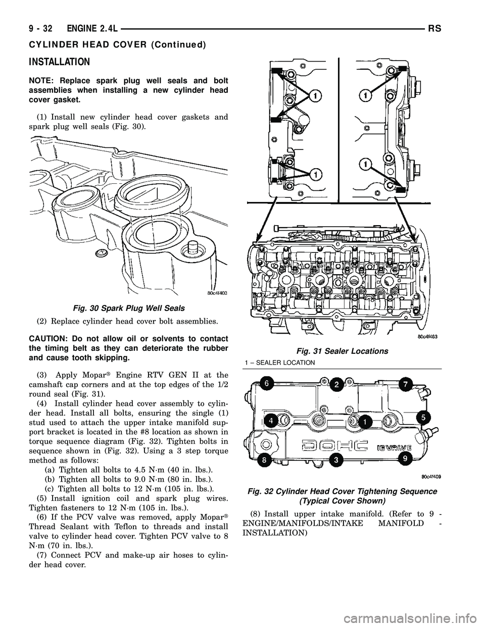
(1) Install new cylinder head cover gaskets and
spark plug well seals (Fig. 30).
(2) Replace cylinder head cover bolt assemblies.
CAUTION: Do not allow oil or solvents to contact
the timing belt as they can deteriorate the rubber
and cause tooth skipping.
(3) Apply MopartEngine RTV GEN II at the
camshaft cap corners and at the top edges of the 1/2
round seal (Fig. 31).
(4) Install cylinder head cover assembly to cylin-
der head. Install all bolts, ensuring the single (1)
stud used to attach the upper intake manifold sup-
port bracket is located in the #8 location as shown in
torque sequence diagram (Fig. 32). Tighten bolts in
sequence shown in (Fig. 32). Using a 3 step torque
method as follows:
(a) Tighten all bolts to 4.5 N´m (40 in. lbs.).
(b) Tighten all bolts to 9.0 N´m (80 in. lbs.).
(c) Tighten all bolts to 12 N´m (105 in. lbs.).
(5) Install ignition coil and spark plug wires.
Tighten fasteners to 12 N´m (105 in. lbs.).
(6) If the PCV valve was removed, apply Mopart
Thread Sealant with Teflon to threads and install
valve to cylinder head cover. Tighten PCV valve to 8
N´m (70 in. lbs.).
(7) Connect PCV and make-up air hoses to cylin-
der head cover.(8) Install upper intake manifold. (Refer to 9 -
ENGINE/MANIFOLDS/INTAKE MANIFOLD -
INSTALLATION)
Fig. 30 Spark Plug Well Seals
Fig. 31 Sealer Locations
1 ± SEALER LOCATION
Fig. 32 Cylinder Head Cover Tightening Sequence
(Typical Cover Shown)
9 - 32 ENGINE 2.4LRS
CYLINDER HEAD COVER (Continued)
Page 1215 of 2339

(6) Drain engine oil and remove oil filter.
(7) Remove crankshaft vibration damper (Refer to
9 - ENGINE/ENGINE BLOCK/VIBRATION
DAMPER - REMOVAL).
(8) Remove engine mount support bracket.
(9) Remove front timing belt covers (Refer to 9 -
ENGINE/VALVE TIMING/TIMING BELT COVER(S)
- REMOVAL).
(10) Remove the timing belt (Refer to 9 - ENGINE/
VALVE TIMING/TIMING BELT AND SPROCKETS -
REMOVAL).
(11) Remove the rear timing belt cover (Refer to 9
- ENGINE/VALVE TIMING/TIMING BELT COV-
ER(S) - REMOVAL).
(12) Remove the oil pan (Refer to 9 - ENGINE/LU-
BRICATION/OIL PAN - REMOVAL).
(13) Remove oil pump pick-up tube.
(14) Remove the crankshaft sprocket and oil pump
(Refer to 9 - ENGINE/LUBRICATION/OIL PUMP -
REMOVAL).
(15) Remove balance shafts and housing assembly
(Refer to 9 - ENGINE/VALVE TIMING/BALANCE
SHAFT - REMOVAL).
(16) Remove crankshaft position sensor.
NOTE: If piston/connecting rod replacement is nec-
essary, remove cylinder head (Refer to 9 - ENGINE/
CYLINDER HEAD - REMOVAL).
(17) Using a permanent ink or paint marker, iden-
tify cylinder number on each connecting rod cap (Fig.
44).
CAUTION: DO NOT use a number stamp or a punch
to mark connecting rods. Damage to connecting
rod could occur.
(18) Remove all connecting rod bolts and caps.
Care should be taken not to damage the fracture rod
and cap surfaces.
NOTE: Do not reuse connecting rod bolts.(19) Remove all bed plate bolts from the engine
block (Fig. 45).
(20) Using a mallet gently tap the bed plate loose
from the engine block dowel pins.
CAUTION: Do not pry up on one side of the bed
plate. Damage may occur to cylinder block to bed
plate alignment and thrust bearing.
(21) Bed plate should be removed evenly from the
cylinder block dowel pins to prevent damage to the
dowel pins and thrust bearing.
CAUTION: Use extreme care when handling crank-
shaft. Tone wheel damage can occur if crankshaft is
mis-handled.
(22) Lift out crankshaft from cylinder block. Do
not damage the main bearings or journals when
removing the crankshaft.
(23) Remove the target ring mounting screws and
discard.
(24) Remove the target ring from the crankshaft.
INSPECTION
For crankshaft specifications (Refer to 9 - ENGINE
- SPECIFICATIONS).
The crankshaft journals should be checked for
excessive wear, taper and scoring (Fig. 46). Limits of
taper or out of round on any crankshaft journals
should be held to 0.025 mm (0.001 in.). Journal
grinding should not exceed 0.305 mm (0.012 in.)
under the standard journal diameter. DO NOT grind
Fig. 44 Identify Connecting Rod to Cylinder-Typical
Fig. 45 Bed Plate Bolt Removal Sequence
9 - 38 ENGINE 2.4LRS
CRANKSHAFT (Continued)
Page 1218 of 2339
(14) Turn bolts (1±10) an additional 1/4 turn in
sequence shown in (Fig. 51).
(15) Install main bearing bed plate to engine
block bolts (11±20), and torque each bolt to 28 N´m
(250 in. lbs.) in sequence shown in. (Fig. 51)
(16) Tighten bolts (11±20) again to 28 N´m (250 in.
lbs.) in sequence shown in (Fig. 51).
(17) After the main bearing bed plate is installed,
check the crankshaft turning torque. The turning
torque should not exceed 5.6 N´m (50 in. lbs.).
(18) Check crankshaft end play (Refer to 9 -
ENGINE/ENGINE BLOCK/CRANKSHAFT - STAN-
DARD PROCEDURE).
(19) Install connecting rod bearings and caps.Do
Not Reuse Connecting Rod Bolts.Torque connect-
ing rod bolts to 27 N´m (20 ft. lbs.) plus 1/4 turn.
(20) Install balance shafts and housing assembly
(Refer to 9 - ENGINE/VALVE TIMING/BALANCE
SHAFT - INSTALLATION).
(21) Install the oil pump (Refer to 9 - ENGINE/
LUBRICATION/OIL PUMP - INSTALLATION).
(22) Install oil pump pick-up tube. Torque fastener
to 28 N´m (20 ft.. lbs.).
(23) Install the oil pan (Refer to 9 - ENGINE/LU-
BRICATION/OIL PAN - INSTALLATION).
(24) Install crankshaft position sensor.
(25) Install cylinder head if it was removed (Refer
to 9 - ENGINE/CYLINDER HEAD - INSTALLA-
TION).
(26) Install the timing belt rear cover (Refer to 9 -
ENGINE/VALVE TIMING/TIMING BELT COVER(S)
- INSTALLATION).
(27) Install crankshaft sprocket (Refer to 9 -
ENGINE/VALVE TIMING/TIMING BELT AND
SPROCKETS - INSTALLATION).
(28) Install the timing belt (Refer to 9 - ENGINE/
VALVE TIMING/TIMING BELT AND SPROCKETS -
INSTALLATION).
(29) Install the timing belt front covers (Refer to 9
- ENGINE/VALVE TIMING/TIMING BELT COV-
ER(S) - INSTALLATION).
(30) Install engine mount support bracket.
(31) InstallNEWoil filter.
(32) Install crankshaft rear oil seal (Refer to 9 -
ENGINE/ENGINE BLOCK/CRANKSHAFT OIL
SEAL - REAR - INSTALLATION).
(33) Install flex plate. Apply MopartLock & Seal
Adhesive to bolt threads and tighten to 95 N´m (70
ft. lbs.).
(34) Attach transaxle to engine. Tighten attaching
bolts to 101 N´m (75 ft. lbs.).
(35) Install the engine assembly (Refer to 9 -
ENGINE - INSTALLATION).CRANKSHAFT OIL SEAL -
FRONT
REMOVAL
(1) Remove the crankshaft vibration damper.
(Refer to 9 - ENGINE/ENGINE BLOCK/VIBRATION
DAMPER - REMOVAL)
(2) Remove timing belt. (Refer to 9 - ENGINE/
VALVE TIMING/TIMING BELT/CHAIN AND
SPROCKETS - REMOVAL)
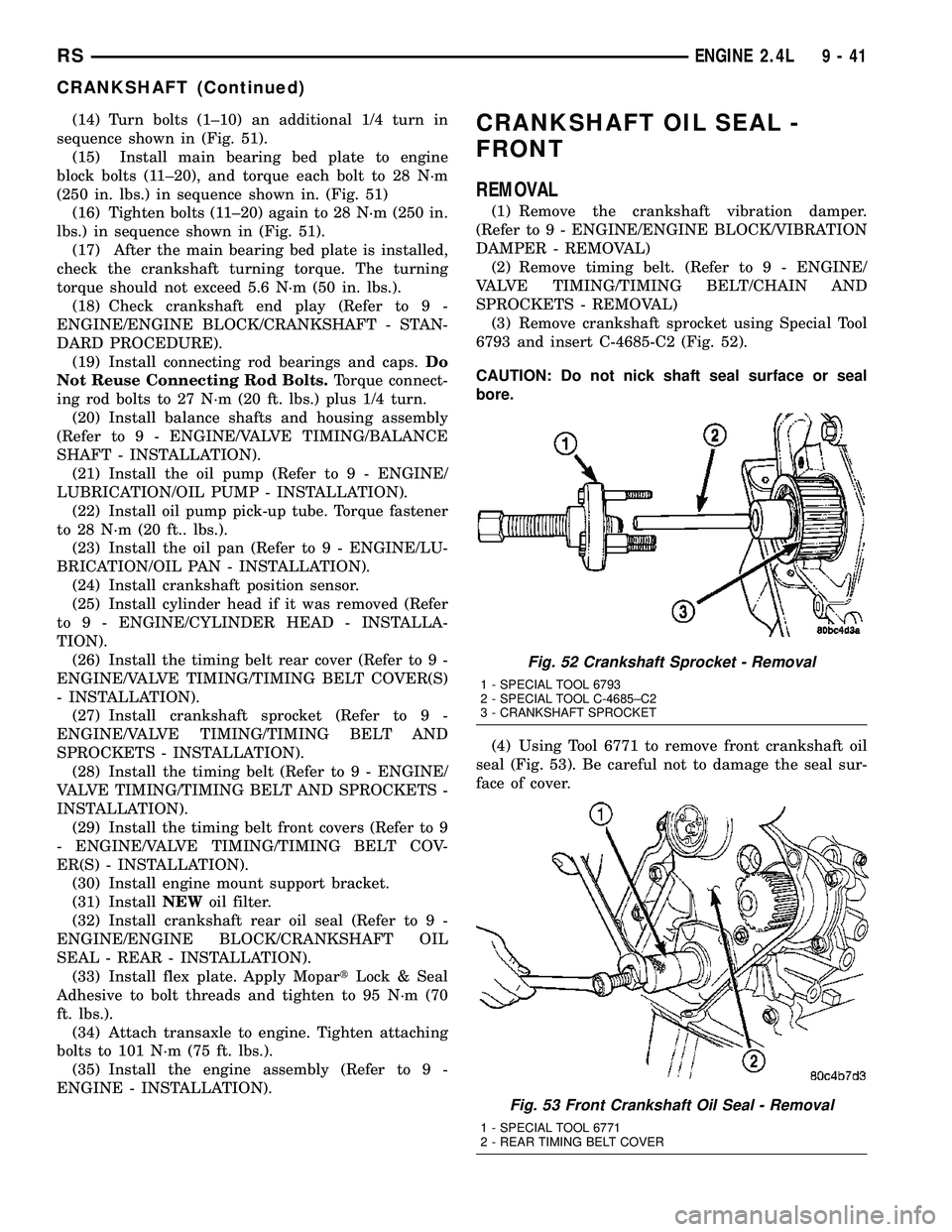
(3) Remove crankshaft sprocket using Special Tool
6793 and insert C-4685-C2 (Fig. 52).
CAUTION: Do not nick shaft seal surface or seal
bore.
(4) Using Tool 6771 to remove front crankshaft oil
seal (Fig. 53). Be careful not to damage the seal sur-
face of cover.
Fig. 52 Crankshaft Sprocket - Removal
1 - SPECIAL TOOL 6793
2 - SPECIAL TOOL C-4685±C2
3 - CRANKSHAFT SPROCKET
Fig. 53 Front Crankshaft Oil Seal - Removal
1 - SPECIAL TOOL 6771
2 - REAR TIMING BELT COVER
RSENGINE 2.4L9-41
CRANKSHAFT (Continued)
Page 1219 of 2339
INSTALLATION
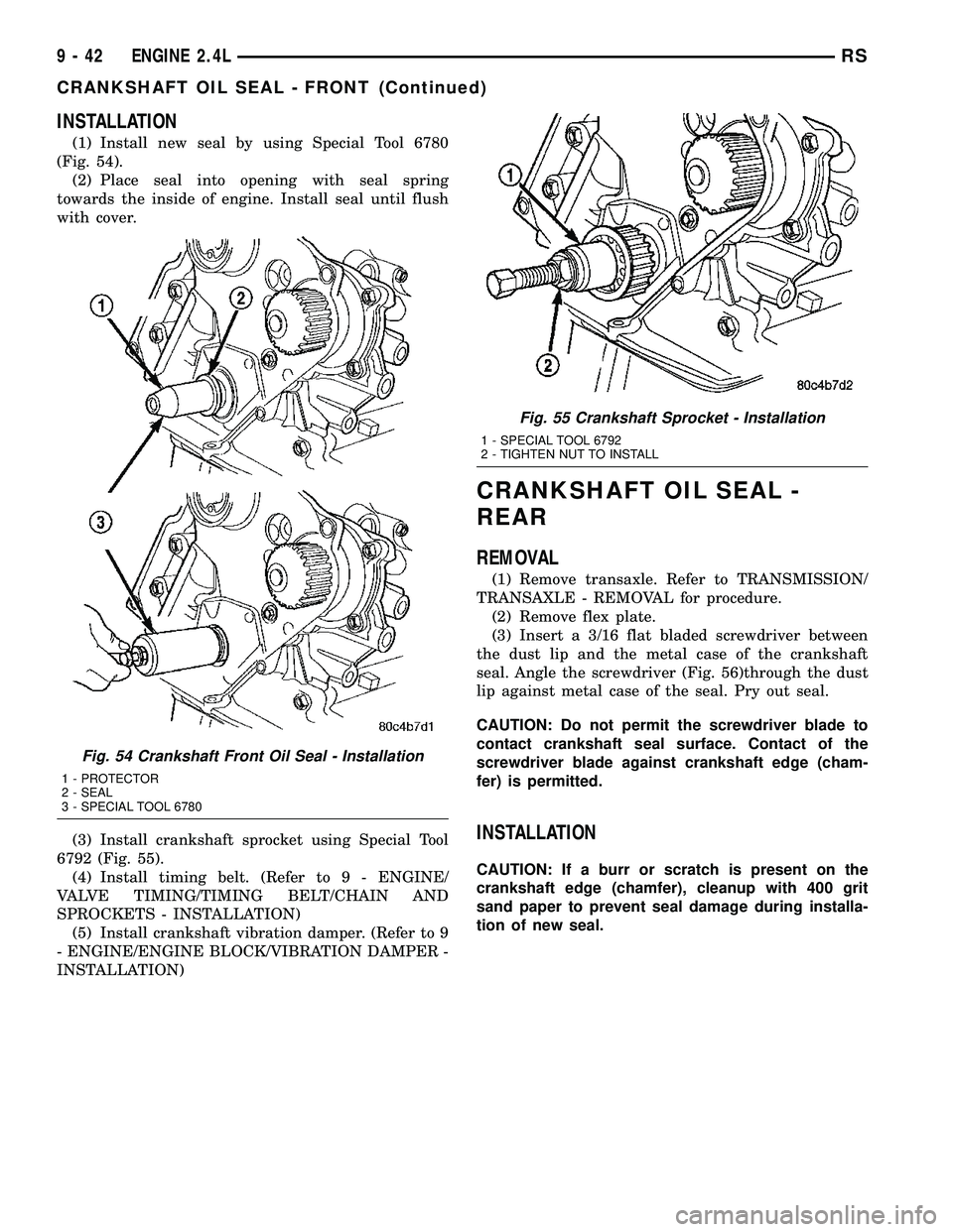
(1) Install new seal by using Special Tool 6780
(Fig. 54).
(2) Place seal into opening with seal spring
towards the inside of engine. Install seal until flush
with cover.
(3) Install crankshaft sprocket using Special Tool
6792 (Fig. 55).
(4) Install timing belt. (Refer to 9 - ENGINE/
VALVE TIMING/TIMING BELT/CHAIN AND
SPROCKETS - INSTALLATION)
(5) Install crankshaft vibration damper. (Refer to 9
- ENGINE/ENGINE BLOCK/VIBRATION DAMPER -
INSTALLATION)
CRANKSHAFT OIL SEAL -
REAR
REMOVAL
(1) Remove transaxle. Refer to TRANSMISSION/
TRANSAXLE - REMOVAL for procedure.
(2) Remove flex plate.
(3) Insert a 3/16 flat bladed screwdriver between
the dust lip and the metal case of the crankshaft
seal. Angle the screwdriver (Fig. 56)through the dust
lip against metal case of the seal. Pry out seal.
CAUTION: Do not permit the screwdriver blade to
contact crankshaft seal surface. Contact of the
screwdriver blade against crankshaft edge (cham-
fer) is permitted.
INSTALLATION
CAUTION: If a burr or scratch is present on the
crankshaft edge (chamfer), cleanup with 400 grit
sand paper to prevent seal damage during installa-
tion of new seal.
Fig. 54 Crankshaft Front Oil Seal - Installation
1 - PROTECTOR
2 - SEAL
3 - SPECIAL TOOL 6780
Fig. 55 Crankshaft Sprocket - Installation
1 - SPECIAL TOOL 6792
2 - TIGHTEN NUT TO INSTALL
9 - 42 ENGINE 2.4LRS
CRANKSHAFT OIL SEAL - FRONT (Continued)
Page 1225 of 2339
4. No. 2 Intermediate piston ring.
5. No. 1 Upper piston ring.
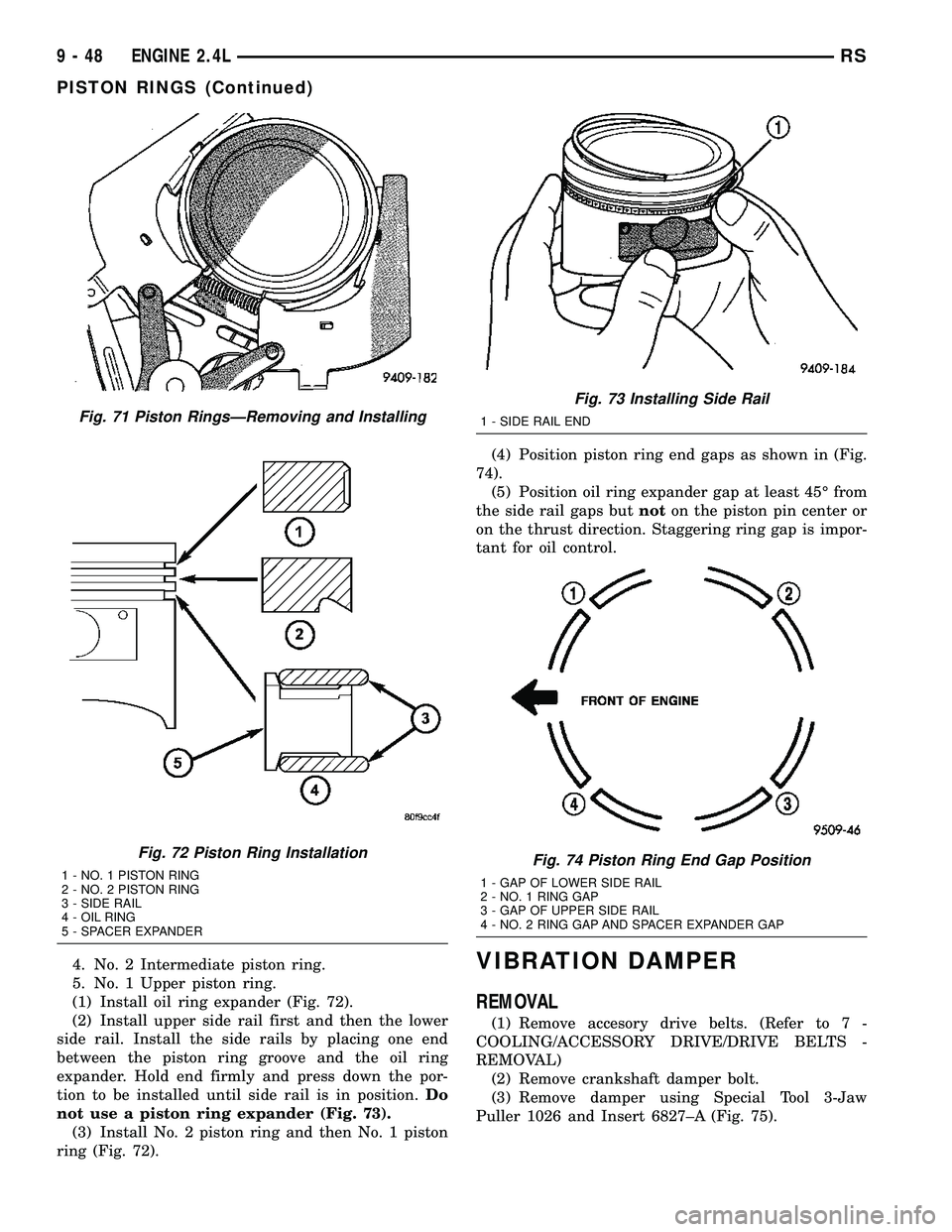
(1) Install oil ring expander (Fig. 72).
(2) Install upper side rail first and then the lower
side rail. Install the side rails by placing one end
between the piston ring groove and the oil ring
expander. Hold end firmly and press down the por-
tion to be installed until side rail is in position.Do
not use a piston ring expander (Fig. 73).
(3) Install No. 2 piston ring and then No. 1 piston
ring (Fig. 72).(4) Position piston ring end gaps as shown in (Fig.
74).
(5) Position oil ring expander gap at least 45É from
the side rail gaps butnoton the piston pin center or
on the thrust direction. Staggering ring gap is impor-
tant for oil control.VIBRATION DAMPER
REMOVAL
(1) Remove accesory drive belts. (Refer to 7 -
COOLING/ACCESSORY DRIVE/DRIVE BELTS -
REMOVAL)
(2) Remove crankshaft damper bolt.
(3) Remove damper using Special Tool 3-Jaw
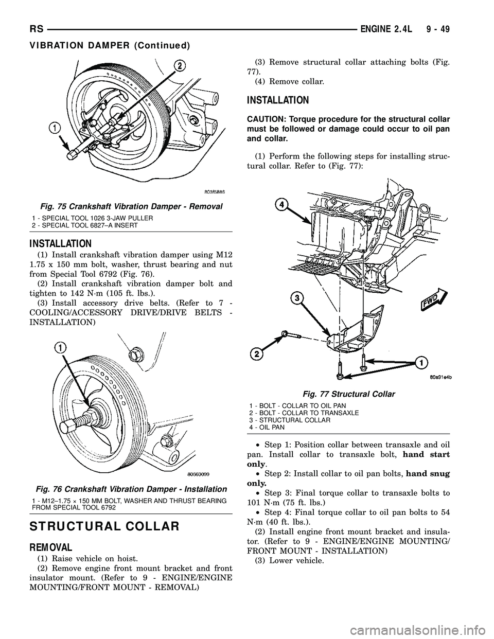
Puller 1026 and Insert 6827±A (Fig. 75).
Fig. 71 Piston RingsÐRemoving and Installing
Fig. 72 Piston Ring Installation
1 - NO. 1 PISTON RING
2 - NO. 2 PISTON RING
3 - SIDE RAIL
4 - OIL RING
5 - SPACER EXPANDER
Fig. 73 Installing Side Rail
1 - SIDE RAIL END
Fig. 74 Piston Ring End Gap Position
1 - GAP OF LOWER SIDE RAIL
2 - NO. 1 RING GAP
3 - GAP OF UPPER SIDE RAIL
4 - NO. 2 RING GAP AND SPACER EXPANDER GAP
9 - 48 ENGINE 2.4LRS
PISTON RINGS (Continued)
Page 1226 of 2339
INSTALLATION
(1) Install crankshaft vibration damper using M12
1.75 x 150 mm bolt, washer, thrust bearing and nut
from Special Tool 6792 (Fig. 76).
(2) Install crankshaft vibration damper bolt and
tighten to 142 N´m (105 ft. lbs.).
(3) Install accessory drive belts. (Refer to 7 -
COOLING/ACCESSORY DRIVE/DRIVE BELTS -
INSTALLATION)
STRUCTURAL COLLAR
REMOVAL
(1) Raise vehicle on hoist.
(2) Remove engine front mount bracket and front
insulator mount. (Refer to 9 - ENGINE/ENGINE
MOUNTING/FRONT MOUNT - REMOVAL)(3) Remove structural collar attaching bolts (Fig.
77).
(4) Remove collar.
INSTALLATION
CAUTION: Torque procedure for the structural collar
must be followed or damage could occur to oil pan
and collar.
(1) Perform the following steps for installing struc-
tural collar. Refer to (Fig. 77):
²Step 1: Position collar between transaxle and oil
pan. Install collar to transaxle bolt,hand start
only.
²Step 2: Install collar to oil pan bolts,hand snug
only.
²Step 3: Final torque collar to transaxle bolts to
101 N´m (75 ft. lbs.)
²Step 4: Final torque collar to oil pan bolts to 54
N´m (40 ft. lbs.).
(2) Install engine front mount bracket and insula-
tor. (Refer to 9 - ENGINE/ENGINE MOUNTING/
FRONT MOUNT - INSTALLATION)
(3) Lower vehicle.
Fig. 75 Crankshaft Vibration Damper - Removal
1 - SPECIAL TOOL 1026 3-JAW PULLER
2 - SPECIAL TOOL 6827±A INSERT
Fig. 76 Crankshaft Vibration Damper - Installation
1 - M12±1.75 ý 150 MM BOLT, WASHER AND THRUST BEARING
FROM SPECIAL TOOL 6792
Fig. 77 Structural Collar
1 - BOLT - COLLAR TO OIL PAN
2 - BOLT - COLLAR TO TRANSAXLE
3 - STRUCTURAL COLLAR
4 - OIL PAN
RSENGINE 2.4L9-49
VIBRATION DAMPER (Continued)
Page 1233 of 2339
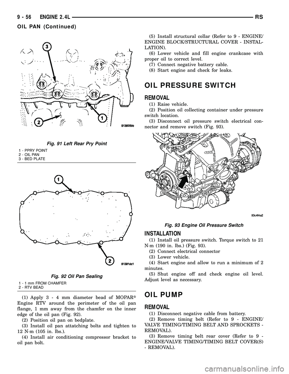
(1) Apply3-4mmdiameter bead of MOPARt
Engine RTV around the perimeter of the oil pan
flange, 1 mm away from the chamfer on the inner
edge of the oil pan (Fig. 92).
(2) Position oil pan on bedplate.
(3) Install oil pan attatching bolts and tighten to
12 N´m (105 in. lbs.).
(4) Install air conditioning compressor bracket to
oil pan bolt.(5) Install structural collar (Refer to 9 - ENGINE/
ENGINE BLOCK/STRUCTURAL COVER - INSTAL-
LATION).
(6) Lower vehicle and fill engine crankcase with
proper oil to correct level.
(7) Connect negative battery cable.
(8) Start engine and check for leaks.
OIL PRESSURE SWITCH
REMOVAL
(1) Raise vehicle.
(2) Position oil collecting container under pressure
switch location.
(3) Disconnect oil pressure switch electrical con-
nector and remove switch (Fig. 93).
INSTALLATION
(1) Install oil pressure switch. Torque switch to 21
N´m (190 in. lbs.) (Fig. 93).
(2) Connect electrical connector
(3) Lower vehicle.
(4) Start engine and allow to run a minimum of 2
minutes.
(5) Shut engine off and check engine oil level.
Adjust level as necessary.
OIL PUMP
REMOVAL
(1) Disconnect negative cable from battery.
(2) Remove timing belt (Refer to 9 - ENGINE/
VALVE TIMING/TIMING BELT AND SPROCKETS -
REMOVAL).
(3) Remove timing belt rear cover (Refer to 9 -
ENGINE/VALVE TIMING/TIMING BELT COVER(S)
- REMOVAL).
Fig. 91 Left Rear Pry Point
1 - PPRY POINT
2 - OIL PAN
3 - BED PLATE
Fig. 92 Oil Pan Sealing
1-1mmFROM CHAMFER
2 - RTV BEAD
Fig. 93 Engine Oil Pressure Switch
9 - 56 ENGINE 2.4LRS
OIL PAN (Continued)
Page 1236 of 2339
INSTALLATION
(1) Make sure all surfaces are clean and free of oil
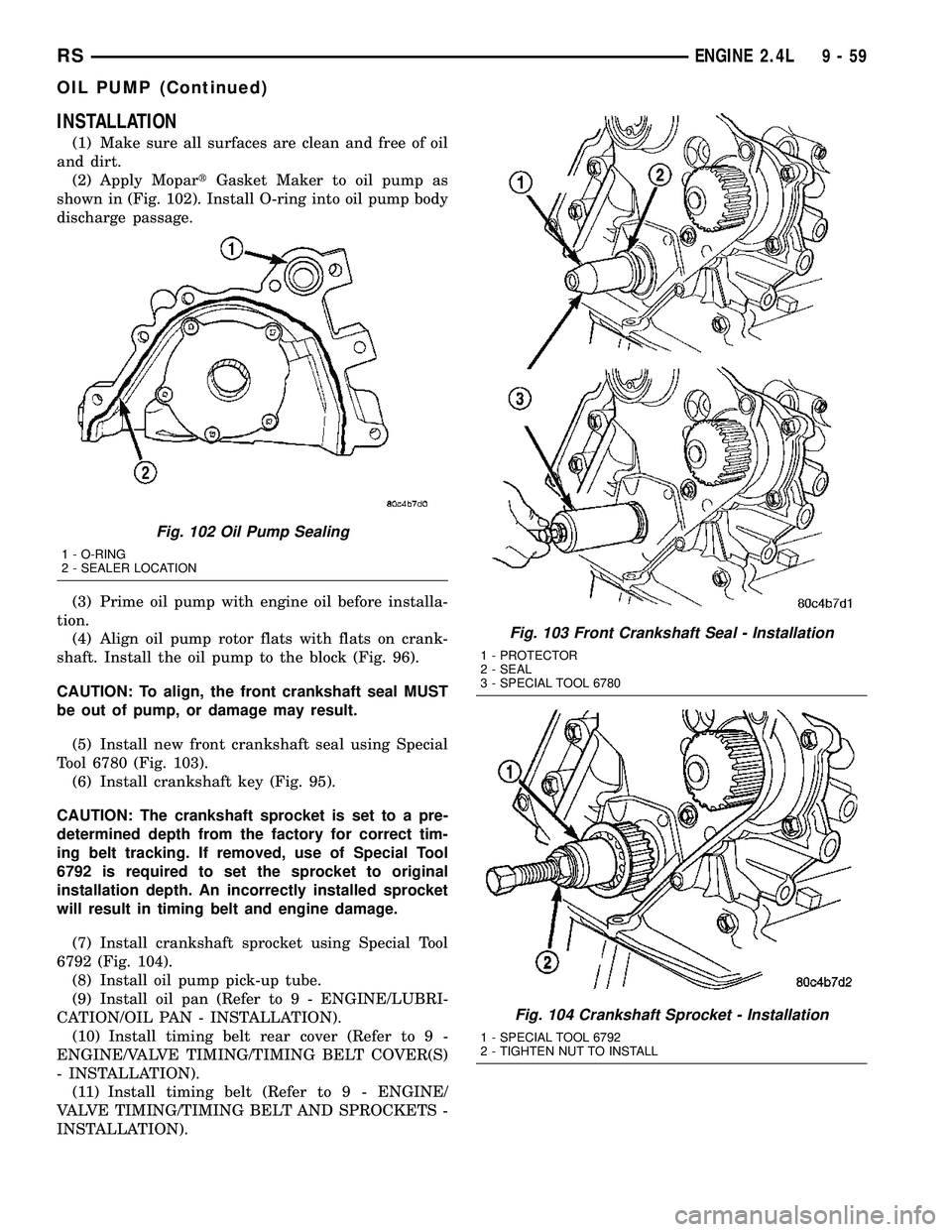
and dirt.
(2) Apply MopartGasket Maker to oil pump as
shown in (Fig. 102). Install O-ring into oil pump body
discharge passage.
(3) Prime oil pump with engine oil before installa-
tion.
(4) Align oil pump rotor flats with flats on crank-
shaft. Install the oil pump to the block (Fig. 96).
CAUTION: To align, the front crankshaft seal MUST
be out of pump, or damage may result.
(5) Install new front crankshaft seal using Special
Tool 6780 (Fig. 103).
(6) Install crankshaft key (Fig. 95).
CAUTION: The crankshaft sprocket is set to a pre-
determined depth from the factory for correct tim-
ing belt tracking. If removed, use of Special Tool
6792 is required to set the sprocket to original
installation depth. An incorrectly installed sprocket
will result in timing belt and engine damage.
(7) Install crankshaft sprocket using Special Tool
6792 (Fig. 104).
(8) Install oil pump pick-up tube.
(9) Install oil pan (Refer to 9 - ENGINE/LUBRI-
CATION/OIL PAN - INSTALLATION).
(10) Install timing belt rear cover (Refer to 9 -
ENGINE/VALVE TIMING/TIMING BELT COVER(S)
- INSTALLATION).
(11) Install timing belt (Refer to 9 - ENGINE/
VALVE TIMING/TIMING BELT AND SPROCKETS -
INSTALLATION).
Fig. 102 Oil Pump Sealing
1 - O-RING
2 - SEALER LOCATION
Fig. 103 Front Crankshaft Seal - Installation
1 - PROTECTOR
2 - SEAL
3 - SPECIAL TOOL 6780
Fig. 104 Crankshaft Sprocket - Installation
1 - SPECIAL TOOL 6792
2 - TIGHTEN NUT TO INSTALL
RSENGINE 2.4L9-59
OIL PUMP (Continued)