2005 CHRYSLER CARAVAN clutch
[x] Cancel search: clutchPage 1612 of 2339
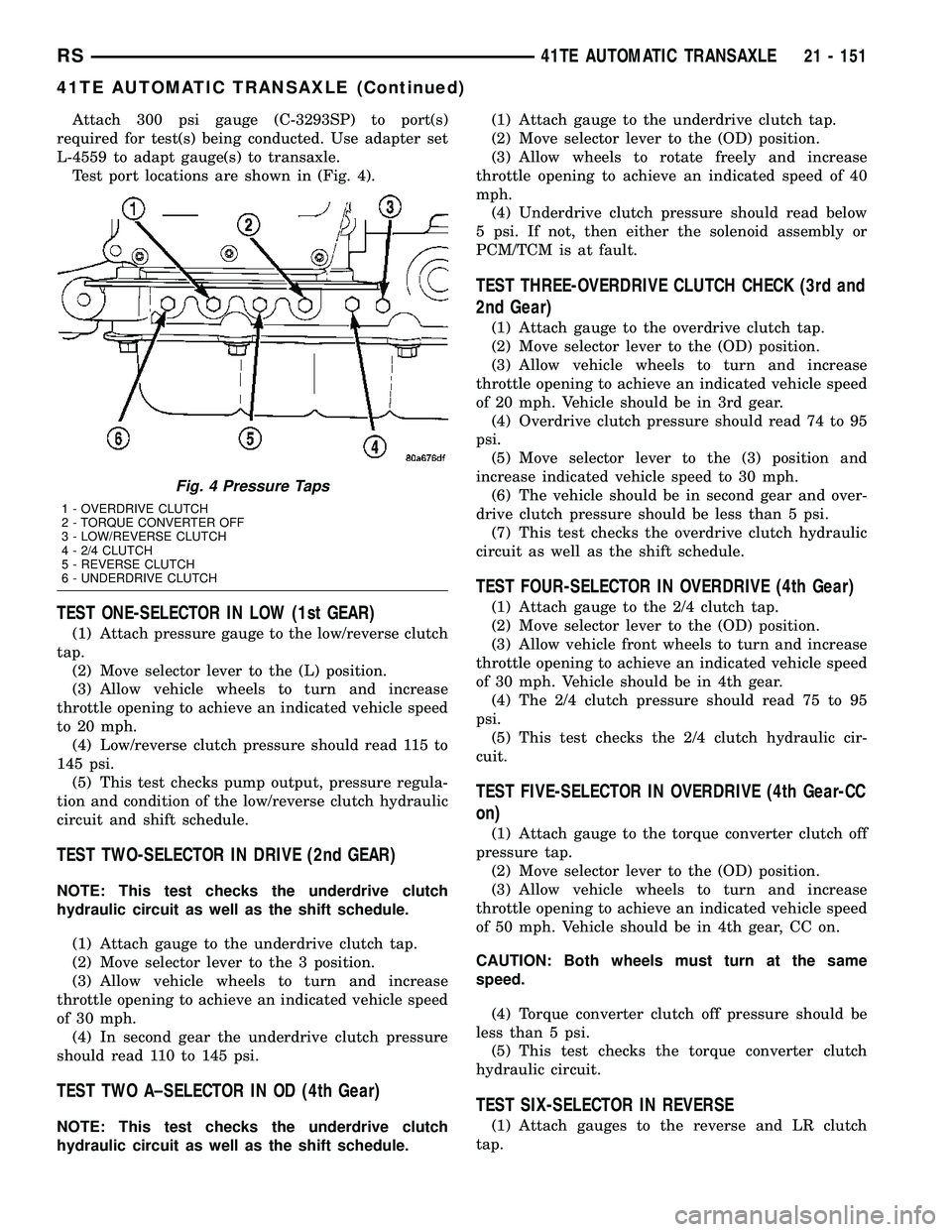
Attach 300 psi gauge (C-3293SP) to port(s)
required for test(s) being conducted. Use adapter set
L-4559 to adapt gauge(s) to transaxle.
Test port locations are shown in (Fig. 4).
TEST ONE-SELECTOR IN LOW (1st GEAR)
(1) Attach pressure gauge to the low/reverse clutch
tap.
(2) Move selector lever to the (L) position.
(3) Allow vehicle wheels to turn and increase
throttle opening to achieve an indicated vehicle speed
to 20 mph.
(4) Low/reverse clutch pressure should read 115 to
145 psi.
(5) This test checks pump output, pressure regula-
tion and condition of the low/reverse clutch hydraulic
circuit and shift schedule.
TEST TWO-SELECTOR IN DRIVE (2nd GEAR)
NOTE: This test checks the underdrive clutch
hydraulic circuit as well as the shift schedule.
(1) Attach gauge to the underdrive clutch tap.
(2) Move selector lever to the 3 position.
(3) Allow vehicle wheels to turn and increase
throttle opening to achieve an indicated vehicle speed
of 30 mph.
(4) In second gear the underdrive clutch pressure
should read 110 to 145 psi.
TEST TWO A±SELECTOR IN OD (4th Gear)
NOTE: This test checks the underdrive clutch
hydraulic circuit as well as the shift schedule.(1) Attach gauge to the underdrive clutch tap.
(2) Move selector lever to the (OD) position.
(3) Allow wheels to rotate freely and increase
throttle opening to achieve an indicated speed of 40
mph.
(4) Underdrive clutch pressure should read below
5 psi. If not, then either the solenoid assembly or
PCM/TCM is at fault.
TEST THREE-OVERDRIVE CLUTCH CHECK (3rd and
2nd Gear)
(1) Attach gauge to the overdrive clutch tap.
(2) Move selector lever to the (OD) position.
(3) Allow vehicle wheels to turn and increase
throttle opening to achieve an indicated vehicle speed
of 20 mph. Vehicle should be in 3rd gear.
(4) Overdrive clutch pressure should read 74 to 95
psi.
(5) Move selector lever to the (3) position and
increase indicated vehicle speed to 30 mph.
(6) The vehicle should be in second gear and over-
drive clutch pressure should be less than 5 psi.
(7) This test checks the overdrive clutch hydraulic
circuit as well as the shift schedule.
TEST FOUR-SELECTOR IN OVERDRIVE (4th Gear)
(1) Attach gauge to the 2/4 clutch tap.
(2) Move selector lever to the (OD) position.
(3) Allow vehicle front wheels to turn and increase
throttle opening to achieve an indicated vehicle speed
of 30 mph. Vehicle should be in 4th gear.
(4) The 2/4 clutch pressure should read 75 to 95
psi.
(5) This test checks the 2/4 clutch hydraulic cir-
cuit.
TEST FIVE-SELECTOR IN OVERDRIVE (4th Gear-CC
on)
(1) Attach gauge to the torque converter clutch off
pressure tap.
(2) Move selector lever to the (OD) position.
(3) Allow vehicle wheels to turn and increase
throttle opening to achieve an indicated vehicle speed
of 50 mph. Vehicle should be in 4th gear, CC on.
CAUTION: Both wheels must turn at the same
speed.
(4) Torque converter clutch off pressure should be
less than 5 psi.
(5) This test checks the torque converter clutch
hydraulic circuit.
TEST SIX-SELECTOR IN REVERSE
(1) Attach gauges to the reverse and LR clutch
tap.
Fig. 4 Pressure Taps
1 - OVERDRIVE CLUTCH
2 - TORQUE CONVERTER OFF
3 - LOW/REVERSE CLUTCH
4 - 2/4 CLUTCH
5 - REVERSE CLUTCH
6 - UNDERDRIVE CLUTCH
RS41TE AUTOMATIC TRANSAXLE21 - 151
41TE AUTOMATIC TRANSAXLE (Continued)
Page 1613 of 2339
(2) Move selector lever to the (R) position.
(3) Read reverse clutch pressure with output sta-
tionary (foot on brake) and throttle opened to achieve
1500 rpm.
(4) Reverse and LR clutch pressure should read
165 to 235 psi.
(5) This test checks the reverse clutch hydraulic
circuit.
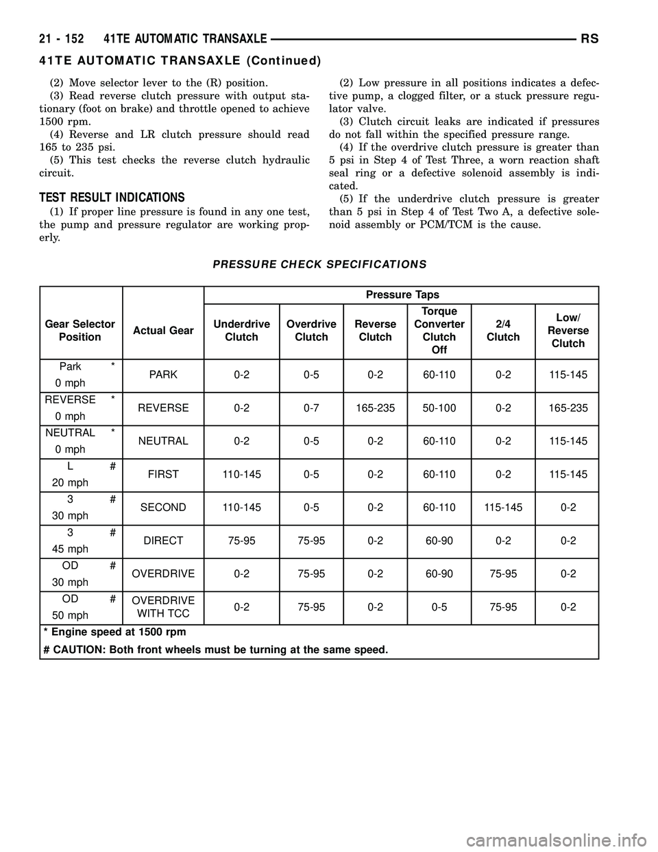
TEST RESULT INDICATIONS
(1) If proper line pressure is found in any one test,
the pump and pressure regulator are working prop-
erly.(2) Low pressure in all positions indicates a defec-
tive pump, a clogged filter, or a stuck pressure regu-
lator valve.
(3) Clutch circuit leaks are indicated if pressures
do not fall within the specified pressure range.
(4) If the overdrive clutch pressure is greater than
5 psi in Step 4 of Test Three, a worn reaction shaft
seal ring or a defective solenoid assembly is indi-
cated.
(5) If the underdrive clutch pressure is greater
than 5 psi in Step 4 of Test Two A, a defective sole-
noid assembly or PCM/TCM is the cause.
PRESSURE CHECK SPECIFICATIONS
Pressure Taps
Gear Selector
PositionActual GearUnderdrive
ClutchOverdrive
ClutchReverse
ClutchTorque
Converter
Clutch
Off2/4
ClutchLow/
Reverse
Clutch
Park *
PARK 0-2 0-5 0-2 60-110 0-2 115-145
0 mph
REVERSE *
REVERSE 0-2 0-7 165-235 50-100 0-2 165-235
0 mph
NEUTRAL *
NEUTRAL 0-2 0-5 0-2 60-110 0-2 115-145
0 mph
L#
FIRST 110-145 0-5 0-2 60-110 0-2 115-145
20 mph
3#
SECOND 110-145 0-5 0-2 60-110 115-145 0-2
30 mph
3#
DIRECT 75-95 75-95 0-2 60-90 0-2 0-2
45 mph
OD #
OVERDRIVE 0-2 75-95 0-2 60-90 75-95 0-2
30 mph
OD #
OVERDRIVE
WITH TCC0-2 75-95 0-2 0-5 75-95 0-2
50 mph
* Engine speed at 1500 rpm
# CAUTION: Both front wheels must be turning at the same speed.
21 - 152 41TE AUTOMATIC TRANSAXLERS
41TE AUTOMATIC TRANSAXLE (Continued)
Page 1614 of 2339
DIAGNOSIS AND TESTING - CLUTCH AIR
PRESSURE TESTS
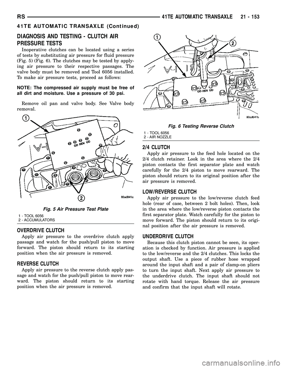
Inoperative clutches can be located using a series
of tests by substituting air pressure for fluid pressure
(Fig. 5) (Fig. 6). The clutches may be tested by apply-
ing air pressure to their respective passages. The
valve body must be removed and Tool 6056 installed.
To make air pressure tests, proceed as follows:
NOTE: The compressed air supply must be free of
all dirt and moisture. Use a pressure of 30 psi.
Remove oil pan and valve body. See Valve body
removal.
OVERDRIVE CLUTCH
Apply air pressure to the overdrive clutch apply
passage and watch for the push/pull piston to move
forward. The piston should return to its starting
position when the air pressure is removed.
REVERSE CLUTCH
Apply air pressure to the reverse clutch apply pas-
sage and watch for the push/pull piston to move rear-
ward. The piston should return to its starting
position when the air pressure is removed.
2/4 CLUTCH
Apply air pressure to the feed hole located on the
2/4 clutch retainer. Look in the area where the 2/4
piston contacts the first separator plate and watch
carefully for the 2/4 piston to move rearward. The
piston should return to its original position after the
air pressure is removed.
LOW/REVERSE CLUTCH
Apply air pressure to the low/reverse clutch feed
hole (rear of case, between 2 bolt holes). Then, look
in the area where the low/reverse piston contacts the
first separator plate. Watch carefully for the piston to
move forward. The piston should return to its origi-
nal position after the air pressure is removed.
UNDERDRIVE CLUTCH
Because this clutch piston cannot be seen, its oper-
ation is checked by function. Air pressure is applied
to the low/reverse and the 2/4 clutches. This locks the
output shaft. Use a piece of rubber hose wrapped
around the input shaft and a pair of clamp-on pliers
to turn the input shaft. Next apply air pressure to
the underdrive clutch. The input shaft should not
rotate with hand torque. Release the air pressure
and confirm that the input shaft will rotate.
Fig. 5 Air Pressure Test Plate
1 - TOOL 6056
2 - ACCUMULATORS
Fig. 6 Testing Reverse Clutch
1 - TOOL 6056
2 - AIR NOZZLE
RS41TE AUTOMATIC TRANSAXLE21 - 153
41TE AUTOMATIC TRANSAXLE (Continued)
Page 1615 of 2339
DIAGNOSIS AND TESTING - TORQUE
CONVERTER HOUSING FLUID LEAKAGE
When diagnosing converter housing fluid leaks,
three actions must be taken before repair:
(1) Verify proper transmission fluid level.
(2) Verify that the leak originates from the con-
verter housing area and is transmission fluid.
(3) Determine the true source of the leak.
Fluid leakage at or around the torque converter area
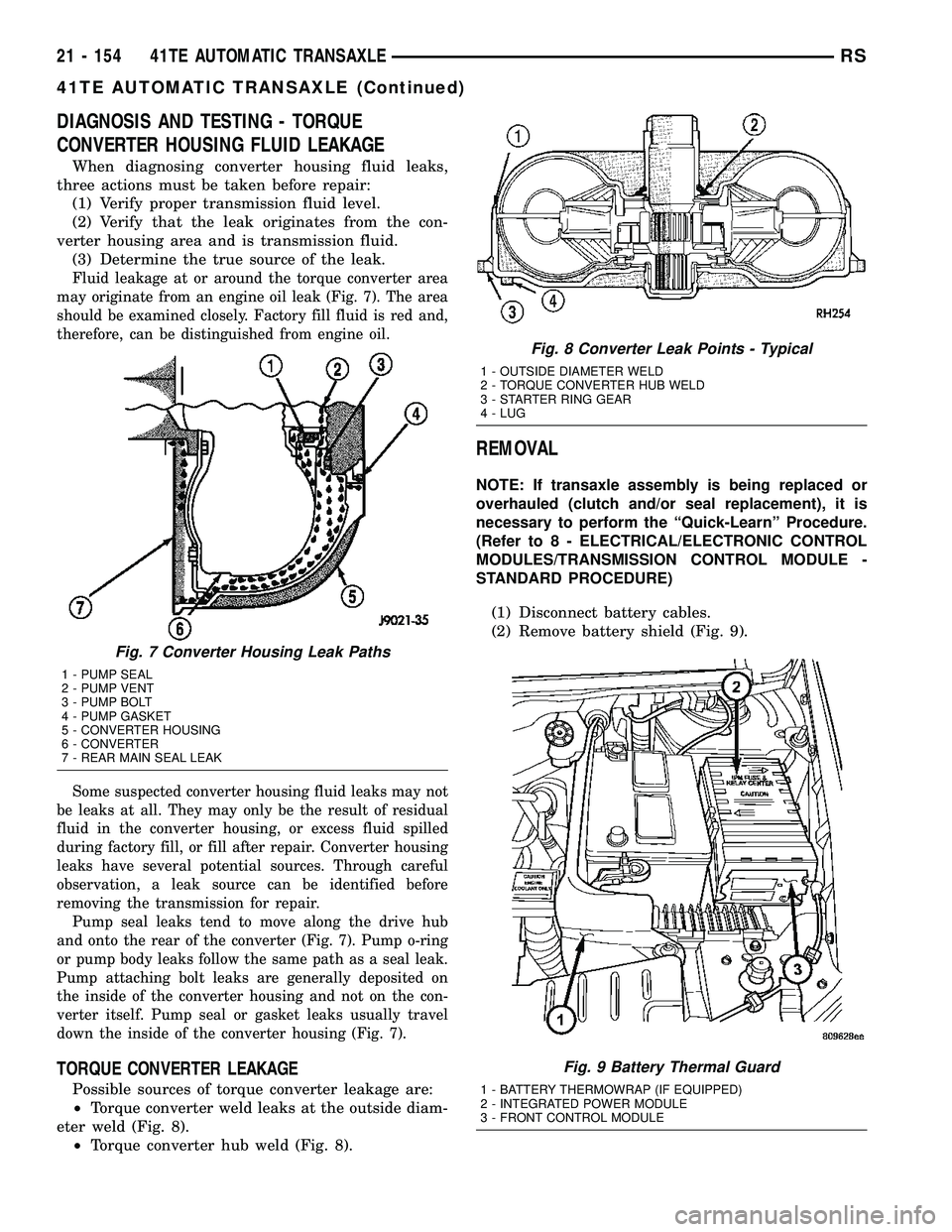
may originate from an engine oil leak (Fig. 7). The area
should be examined closely. Factory fill fluid is red and,
therefore, can be distinguished from engine oil.
Some suspected converter housing fluid leaks may not
be leaks at all. They may only be the result of residual
fluid in the converter housing, or excess fluid spilled
during factory fill, or fill after repair. Converter housing
leaks have several potential sources. Through careful
observation, a leak source can be identified before
removing the transmission for repair.
Pump seal leaks tend to move along the drive hub
and onto the rear of the converter (Fig. 7). Pump o-ring
or pump body leaks follow the same path as a seal leak.
Pump attaching bolt leaks are generally deposited on
the inside of the converter housing and not on the con-
verter itself. Pump seal or gasket leaks usually travel
down the inside of the converter housing (Fig. 7).
TORQUE CONVERTER LEAKAGE
Possible sources of torque converter leakage are:
²Torque converter weld leaks at the outside diam-
eter weld (Fig. 8).
²Torque converter hub weld (Fig. 8).
REMOVAL
NOTE: If transaxle assembly is being replaced or
overhauled (clutch and/or seal replacement), it is
necessary to perform the ªQuick-Learnº Procedure.
(Refer to 8 - ELECTRICAL/ELECTRONIC CONTROL
MODULES/TRANSMISSION CONTROL MODULE -
STANDARD PROCEDURE)
(1) Disconnect battery cables.
(2) Remove battery shield (Fig. 9).
Fig. 7 Converter Housing Leak Paths
1 - PUMP SEAL
2 - PUMP VENT
3 - PUMP BOLT
4 - PUMP GASKET
5 - CONVERTER HOUSING
6 - CONVERTER
7 - REAR MAIN SEAL LEAK
Fig. 8 Converter Leak Points - Typical
1 - OUTSIDE DIAMETER WELD
2 - TORQUE CONVERTER HUB WELD
3 - STARTER RING GEAR
4 - LUG
Fig. 9 Battery Thermal Guard
1 - BATTERY THERMOWRAP (IF EQUIPPED)
2 - INTEGRATED POWER MODULE
3 - FRONT CONTROL MODULE
21 - 154 41TE AUTOMATIC TRANSAXLERS
41TE AUTOMATIC TRANSAXLE (Continued)
Page 1618 of 2339

(28) Obtain helper and/or transmission jack.
Secure transmission jack to transaxle assembly.
(29) Remove upper mount bracket from transaxle
(Fig. 14).
(30) Remove remaining transaxle bellhousing-to-
engine bolts.
(31) Remove transaxle assembly from vehicle.
DISASSEMBLY
NOTE: If transaxle is being overhauled (clutch
and/or seal replacement) or replaced, it is neces-
sary to perform the PCM/TCM Quick Learn Proce-
dure. (Refer to 8 - ELECTRICAL/ELECTRONIC
CONTROL MODULES/POWERTRAIN/TRANSMIS-
SION CONTROL MODULE - STANDARD PROCE-
DURE)
NOTE: This procedure does not include final drive
(differential) disassembly.
(1) Remove input and output speed sensors.
(2) Remove three (3) solenoid/pressure switch
assembly-to-case bolts.
(3) Remove solenoid/pressure switch assembly and
gasket (Fig. 15).(4) Remove oil pan-to-case bolts (Fig. 16).
(5) Remove oil pan (Fig. 17).
Fig. 15 Solenoid/Pressure Switch Assembly and
Gasket
1 - SOLENOID/PRESSURE SWITCH ASSEMBLY
2 - GASKET
Fig. 16 Remove Oil Pan Bolts
1 - OIL PAN BOLTS (USE RTV UNDER BOLT HEADS)
Fig. 17 Remove Oil Pan
1 - OIL PAN
2 - 1/8 INCH BEAD OF MOPARTATF RTV (MS-GF41)
3 - OIL FILTER
RS41TE AUTOMATIC TRANSAXLE21 - 157
41TE AUTOMATIC TRANSAXLE (Continued)
Page 1623 of 2339
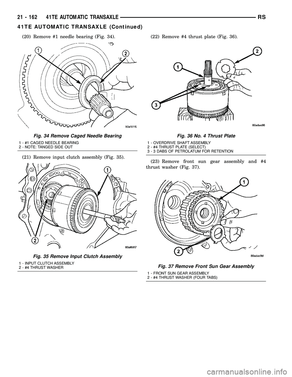
(20) Remove #1 needle bearing (Fig. 34).
(21) Remove input clutch assembly (Fig. 35).(22) Remove #4 thrust plate (Fig. 36).
(23) Remove front sun gear assembly and #4
thrust washer (Fig. 37).
Fig. 34 Remove Caged Needle Bearing
1 - #1 CAGED NEEDLE BEARING
2 - NOTE: TANGED SIDE OUT
Fig. 35 Remove Input Clutch Assembly
1 - INPUT CLUTCH ASSEMBLY
2 - #4 THRUST WASHER
Fig. 36 No. 4 Thrust Plate
1 - OVERDRIVE SHAFT ASSEMBLY
2 - #4 THRUST PLATE (SELECT)
3 - 3 DABS OF PETROLATUM FOR RETENTION
Fig. 37 Remove Front Sun Gear Assembly
1 - FRONT SUN GEAR ASSEMBLY
2 - #4 THRUST WASHER (FOUR TABS)
21 - 162 41TE AUTOMATIC TRANSAXLERS
41TE AUTOMATIC TRANSAXLE (Continued)
Page 1624 of 2339
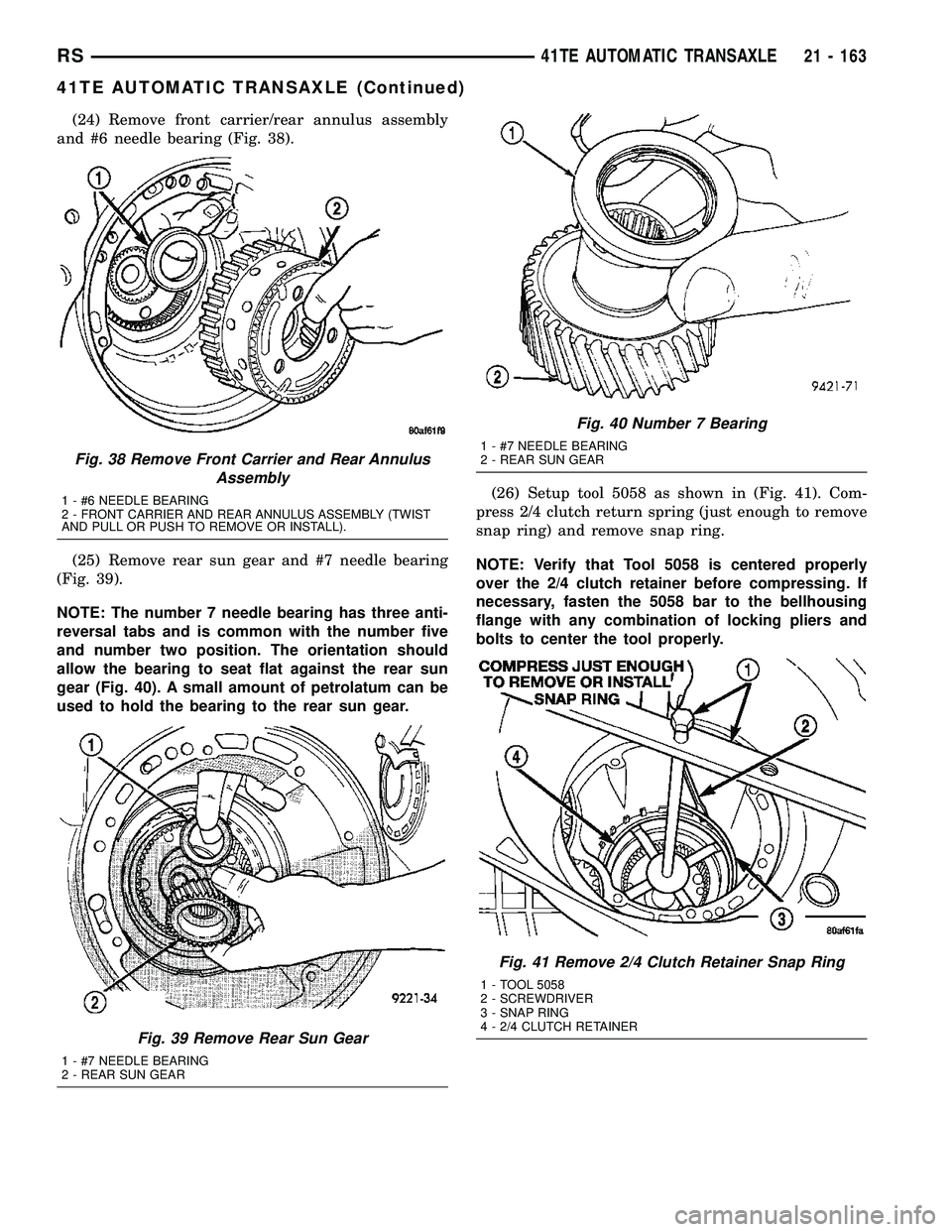
(24) Remove front carrier/rear annulus assembly
and #6 needle bearing (Fig. 38).
(25) Remove rear sun gear and #7 needle bearing
(Fig. 39).
NOTE: The number 7 needle bearing has three anti-
reversal tabs and is common with the number five
and number two position. The orientation should
allow the bearing to seat flat against the rear sun
gear (Fig. 40). A small amount of petrolatum can be
used to hold the bearing to the rear sun gear.(26) Setup tool 5058 as shown in (Fig. 41). Com-
press 2/4 clutch return spring (just enough to remove
snap ring) and remove snap ring.
NOTE: Verify that Tool 5058 is centered properly
over the 2/4 clutch retainer before compressing. If
necessary, fasten the 5058 bar to the bellhousing
flange with any combination of locking pliers and
bolts to center the tool properly.
Fig. 38 Remove Front Carrier and Rear Annulus
Assembly
1 - #6 NEEDLE BEARING
2 - FRONT CARRIER AND REAR ANNULUS ASSEMBLY (TWIST
AND PULL OR PUSH TO REMOVE OR INSTALL).
Fig. 39 Remove Rear Sun Gear
1 - #7 NEEDLE BEARING
2 - REAR SUN GEAR
Fig. 40 Number 7 Bearing
1 - #7 NEEDLE BEARING
2 - REAR SUN GEAR
Fig. 41 Remove 2/4 Clutch Retainer Snap Ring
1 - TOOL 5058
2 - SCREWDRIVER
3 - SNAP RING
4 - 2/4 CLUTCH RETAINER
RS41TE AUTOMATIC TRANSAXLE21 - 163
41TE AUTOMATIC TRANSAXLE (Continued)
Page 1625 of 2339
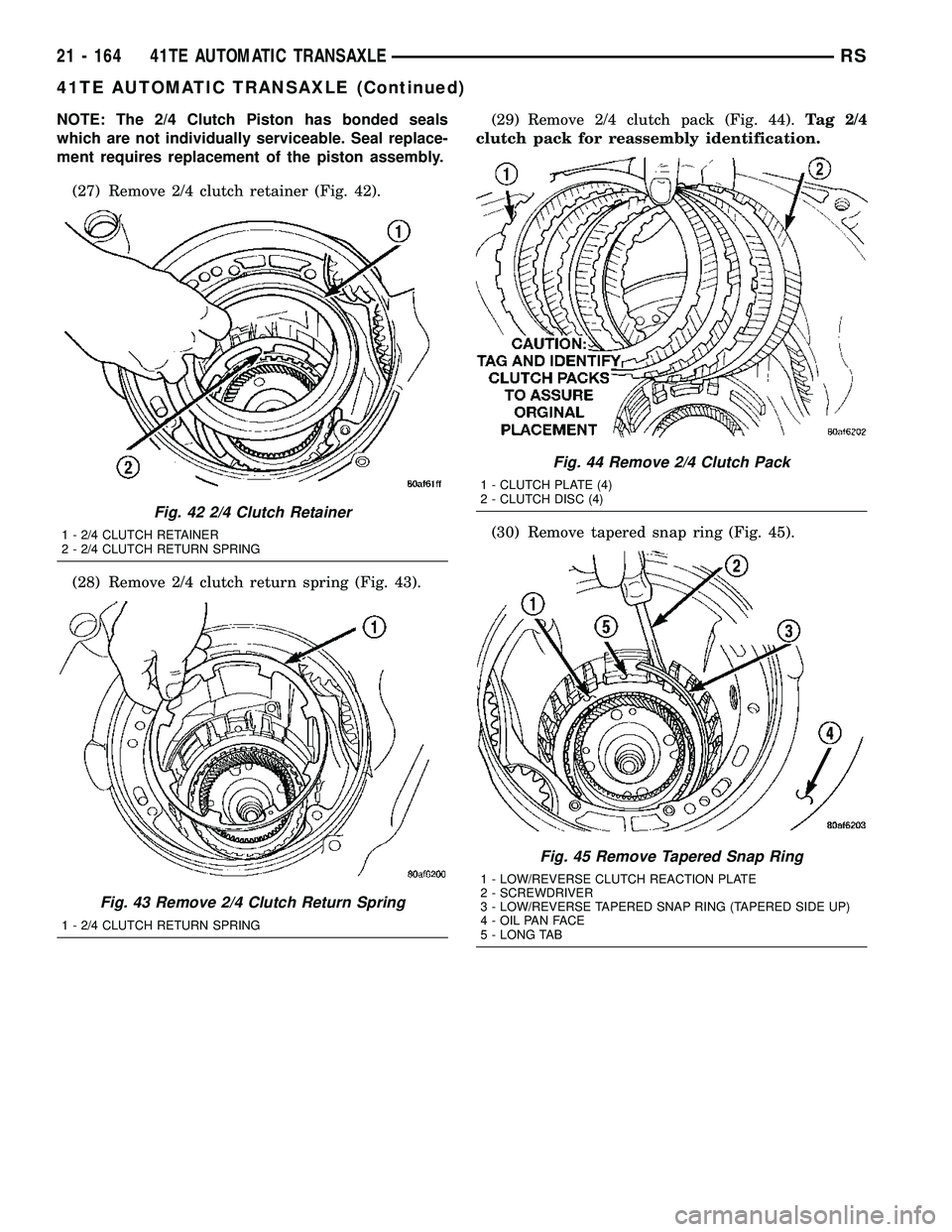
NOTE: The 2/4 Clutch Piston has bonded seals
which are not individually serviceable. Seal replace-
ment requires replacement of the piston assembly.
(27) Remove 2/4 clutch retainer (Fig. 42).
(28) Remove 2/4 clutch return spring (Fig. 43).(29) Remove 2/4 clutch pack (Fig. 44).Tag 2/4
clutch pack for reassembly identification.
(30) Remove tapered snap ring (Fig. 45).
Fig. 42 2/4 Clutch Retainer
1 - 2/4 CLUTCH RETAINER
2 - 2/4 CLUTCH RETURN SPRING
Fig. 43 Remove 2/4 Clutch Return Spring
1 - 2/4 CLUTCH RETURN SPRING
Fig. 44 Remove 2/4 Clutch Pack
1 - CLUTCH PLATE (4)
2 - CLUTCH DISC (4)
Fig. 45 Remove Tapered Snap Ring
1 - LOW/REVERSE CLUTCH REACTION PLATE
2 - SCREWDRIVER
3 - LOW/REVERSE TAPERED SNAP RING (TAPERED SIDE UP)
4 - OIL PAN FACE
5 - LONG TAB
21 - 164 41TE AUTOMATIC TRANSAXLERS
41TE AUTOMATIC TRANSAXLE (Continued)