Page 1680 of 2339

DRIVING CLUTCHES
DESCRIPTION
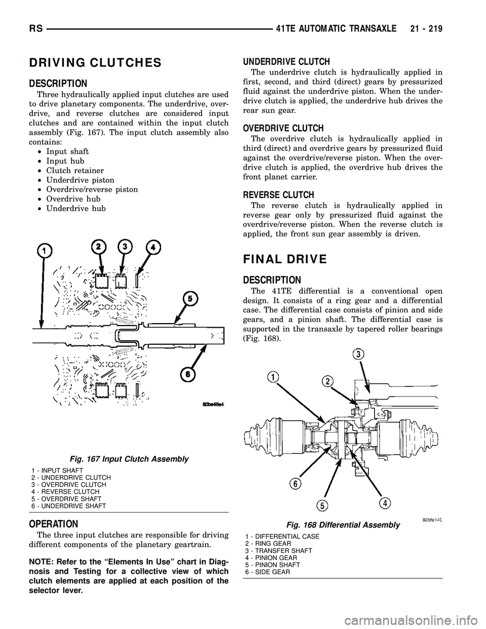
Three hydraulically applied input clutches are used
to drive planetary components. The underdrive, over-
drive, and reverse clutches are considered input
clutches and are contained within the input clutch
assembly (Fig. 167). The input clutch assembly also
contains:
²Input shaft
²Input hub
²Clutch retainer
²Underdrive piston
²Overdrive/reverse piston
²Overdrive hub
²Underdrive hub
OPERATION
The three input clutches are responsible for driving
different components of the planetary geartrain.
NOTE: Refer to the ªElements In Useº chart in Diag-
nosis and Testing for a collective view of which
clutch elements are applied at each position of the
selector lever.
UNDERDRIVE CLUTCH
The underdrive clutch is hydraulically applied in
first, second, and third (direct) gears by pressurized
fluid against the underdrive piston. When the under-
drive clutch is applied, the underdrive hub drives the
rear sun gear.
OVERDRIVE CLUTCH
The overdrive clutch is hydraulically applied in
third (direct) and overdrive gears by pressurized fluid
against the overdrive/reverse piston. When the over-
drive clutch is applied, the overdrive hub drives the
front planet carrier.
REVERSE CLUTCH
The reverse clutch is hydraulically applied in
reverse gear only by pressurized fluid against the
overdrive/reverse piston. When the reverse clutch is
applied, the front sun gear assembly is driven.
FINAL DRIVE
DESCRIPTION
The 41TE differential is a conventional open
design. It consists of a ring gear and a differential
case. The differential case consists of pinion and side
gears, and a pinion shaft. The differential case is
supported in the transaxle by tapered roller bearings
(Fig. 168).
Fig. 167 Input Clutch Assembly
1 - INPUT SHAFT
2 - UNDERDRIVE CLUTCH
3 - OVERDRIVE CLUTCH
4 - REVERSE CLUTCH
5 - OVERDRIVE SHAFT
6 - UNDERDRIVE SHAFT
Fig. 168 Differential Assembly
1 - DIFFERENTIAL CASE
2 - RING GEAR
3 - TRANSFER SHAFT
4 - PINION GEAR
5 - PINION SHAFT
6 - SIDE GEAR
RS41TE AUTOMATIC TRANSAXLE21 - 219
Page 1691 of 2339

CAUTION: Do not damage the transaxle case and/or
differential retainer sealing surface.
(9) Using the end play measurement that was
determined, add 0.18mm (0.007 inch). This should
give you between 5-18 inch pounds of bearing pre-
load. Refer to the Differential Bearing Shim Chart to
determine which shim to use.
(10) Remove the differential bearing retainer.
Remove the bearing cup.
(11) Install the oil baffle. Install the proper shim
combination under the bearing cup.
(12) Install the differential bearing retainer. Seal
the retainer to the housing with MopartSilicone
Rubber Adhesive Sealant. Torque bolts to 28 N´m
(250 in. lbs.).
(13) Using Miller Special Tool L-4436-A and an
inch-pound torque wrench, check the turning torque
of the differential (Fig. 204). The turning torque
should be between 5-18 inch-pounds.
NOTE: If turning torque is too high install a 0.05mm
(0.002 inch) thicker shim. If the turning torque is too
low, install a 0.05mm (0.002 inch) thinner shim.
Repeat until 5-18 inch-pounds of turning torque is
obtained.
FLUID
STANDARD PROCEDURE
FLUID LEVEL AND CONDITION CHECK
NOTE: Only transmission fluid of the type labeled
Mopar ATF+4 (Automatic Transmission Fluid)
should be used in this transaxle.
FLUID LEVEL CHECK
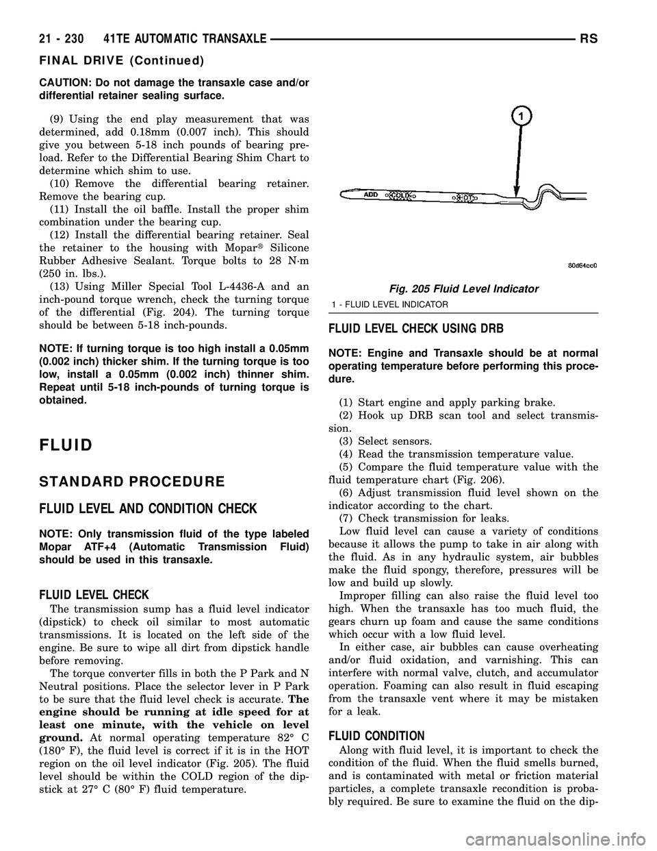
The transmission sump has a fluid level indicator
(dipstick) to check oil similar to most automatic
transmissions. It is located on the left side of the
engine. Be sure to wipe all dirt from dipstick handle
before removing.
The torque converter fills in both the P Park and N
Neutral positions. Place the selector lever in P Park
to be sure that the fluid level check is accurate.The
engine should be running at idle speed for at
least one minute, with the vehicle on level
ground.At normal operating temperature 82É C
(180É F), the fluid level is correct if it is in the HOT
region on the oil level indicator (Fig. 205). The fluid
level should be within the COLD region of the dip-
stick at 27É C (80É F) fluid temperature.
FLUID LEVEL CHECK USING DRB
NOTE: Engine and Transaxle should be at normal
operating temperature before performing this proce-
dure.
(1) Start engine and apply parking brake.
(2) Hook up DRB scan tool and select transmis-
sion.
(3) Select sensors.
(4) Read the transmission temperature value.
(5) Compare the fluid temperature value with the
fluid temperature chart (Fig. 206).
(6) Adjust transmission fluid level shown on the
indicator according to the chart.
(7) Check transmission for leaks.
Low fluid level can cause a variety of conditions
because it allows the pump to take in air along with
the fluid. As in any hydraulic system, air bubbles
make the fluid spongy, therefore, pressures will be
low and build up slowly.
Improper filling can also raise the fluid level too
high. When the transaxle has too much fluid, the
gears churn up foam and cause the same conditions
which occur with a low fluid level.
In either case, air bubbles can cause overheating
and/or fluid oxidation, and varnishing. This can
interfere with normal valve, clutch, and accumulator
operation. Foaming can also result in fluid escaping
from the transaxle vent where it may be mistaken
for a leak.
FLUID CONDITION
Along with fluid level, it is important to check the
condition of the fluid. When the fluid smells burned,
and is contaminated with metal or friction material
particles, a complete transaxle recondition is proba-
bly required. Be sure to examine the fluid on the dip-
Fig. 205 Fluid Level Indicator
1 - FLUID LEVEL INDICATOR
21 - 230 41TE AUTOMATIC TRANSAXLERS
FINAL DRIVE (Continued)
Page 1697 of 2339

(6) Tighten the cable adjustment screw to 8 N´m
(70 in. lbs.). Gearshift cable should now be properly
adjusted.
(7) Verify adjustment by using the verification pro-
cedure.
HOLDING CLUTCHES
DESCRIPTION
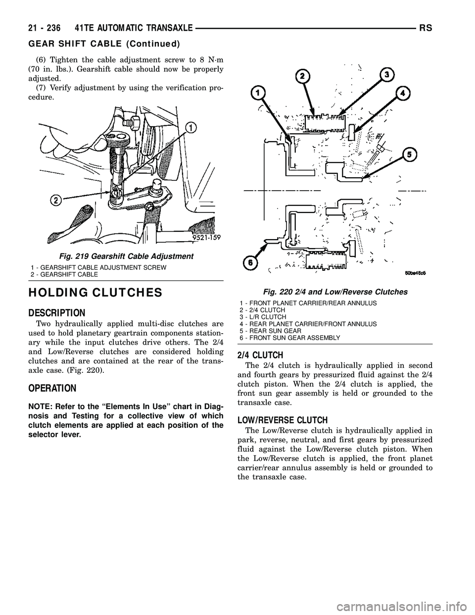
Two hydraulically applied multi-disc clutches are
used to hold planetary geartrain components station-
ary while the input clutches drive others. The 2/4
and Low/Reverse clutches are considered holding
clutches and are contained at the rear of the trans-
axle case. (Fig. 220).
OPERATION
NOTE: Refer to the ªElements In Useº chart in Diag-
nosis and Testing for a collective view of which
clutch elements are applied at each position of the
selector lever.
2/4 CLUTCH
The 2/4 clutch is hydraulically applied in second
and fourth gears by pressurized fluid against the 2/4
clutch piston. When the 2/4 clutch is applied, the
front sun gear assembly is held or grounded to the
transaxle case.
LOW/REVERSE CLUTCH
The Low/Reverse clutch is hydraulically applied in
park, reverse, neutral, and first gears by pressurized
fluid against the Low/Reverse clutch piston. When
the Low/Reverse clutch is applied, the front planet
carrier/rear annulus assembly is held or grounded to
the transaxle case.
Fig. 219 Gearshift Cable Adjustment
1 - GEARSHIFT CABLE ADJUSTMENT SCREW
2 - GEARSHIFT CABLE
Fig. 220 2/4 and Low/Reverse Clutches
1 - FRONT PLANET CARRIER/REAR ANNULUS
2 - 2/4 CLUTCH
3 - L/R CLUTCH
4 - REAR PLANET CARRIER/FRONT ANNULUS
5 - REAR SUN GEAR
6 - FRONT SUN GEAR ASSEMBLY
21 - 236 41TE AUTOMATIC TRANSAXLERS
GEAR SHIFT CABLE (Continued)
Page 1698 of 2339
INPUT CLUTCH ASSEMBLY
DISASSEMBLY
(1) Mount input clutch assembly to Input Clutch
Pressure Fixture (Tool 8391).
(2) Tap down reverse clutch reaction plate to
release pressure from snap ring (Fig. 221).
(3) Remove reverse clutch snap ring (Fig. 222).(4) Pry up and remove reverse clutch reaction
plate (Fig. 223).
Fig. 221 Tapping Reaction Plate
1 - #4 THRUST PLATE (SELECT)
2 - TAP DOWN REVERSE CLUTCH REACTION PLATE TO
REMOVE OR INSTALL SNAP RING
3 - INPUT SHAFT CLUTCHES RETAINER ASSEMBLY
4 - REVERSE CLUTCH REACTION PLATE
Fig. 222 Reverse Clutch Snap Ring
1 - REACTION PLATE
2 - SCREWDRIVER
3 - REVERSE CLUTCH SNAP RING (SELECT)
Fig. 223 Pry Reverse Clutch Reaction Plate
1 - REVERSE CLUTCH REACTION PLATE
2 - SCREWDRIVER
3 - SCREWDRIVER
RS41TE AUTOMATIC TRANSAXLE21 - 237
Page 1699 of 2339
(5) Remove reverse clutch pack (Fig. 224).Ta g
components for assembly identification.
Fig. 224 Reverse Clutch Assembly
1 - SNAP RING
2 - REACTION PLATE
3 - CLUTCH DISC (2)4 - CLUTCH PLATE (1)
5 - INPUT CLUTCH ASSEMBLY
21 - 238 41TE AUTOMATIC TRANSAXLERS
INPUT CLUTCH ASSEMBLY (Continued)
Page 1700 of 2339
(6) Remove the OD/Reverse pressure plate snap
ring (Fig. 225).
(7) Remove OD/Reverse pressure plate (Fig. 225).
(8) Remove OD/Reverse pressure plate wave snap
ring (Fig. 225).
(9) Remove OD clutch pack (Fig. 225).Tag com-
ponents for assembly identification.
Fig. 225 Overdrive Clutch Assembly
1 - SNAP RING
2 - OD/REVERSE PRESSURE PLATE
3 - SNAP RING (WAVE)4 - CLUTCH DISC (4)
5 - CLUTCH STEEL (3)
6 - INPUT CLUTCH ASSEMBLY
RS41TE AUTOMATIC TRANSAXLE21 - 239
INPUT CLUTCH ASSEMBLY (Continued)
Page 1701 of 2339
(10) Remove and inspect OD and UD Shafts, as
well as #3 thrust washer and plate, and #2 needle
bearing (Fig. 226).
Fig. 226 Overdrive/Underdrive Shafts
1 - OVERDRIVE SHAFT
2 - #3 THRUST PLATE (3 TABS)
3 - #3 THRUST WASHER (5 TABS)4 - UNDERDRIVE SHAFT
5 - #2 NEEDLE BEARING (3 TABS)
6 - INPUT CLUTCH ASSEMBLY
21 - 240 41TE AUTOMATIC TRANSAXLERS
INPUT CLUTCH ASSEMBLY (Continued)
Page 1702 of 2339
(11) Remove the OD/UD reaction plate tapered
snap ring, reaction plate, and first friction disc (Fig.
227).
(12) Remove the UD clutch flat snap ring and rest
of UD clutch pack (Fig. 227).Tag clutch pack for
assembly identification.
Fig. 227 Underdrive Clutch Assembly
1 - SNAP RING (TAPERED)
2 - OD/UD REACTION PLATE
3 - CLUTCH DISC4 - SNAP RING (FLAT)
5 - CLUTCH PLATE
6 - INPUT CLUTCH ASSEMBLY
RS41TE AUTOMATIC TRANSAXLE21 - 241
INPUT CLUTCH ASSEMBLY (Continued)