Page 1650 of 2339
NOTE: The 2/4 Clutch Piston has bonded seals
which are not individually serviceable. Seal replace-
ment requires replacement of the piston assembly.
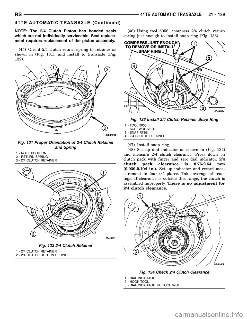
(45) Orient 2/4 clutch return spring to retainer as
shown in (Fig. 131), and install to transaxle (Fig.
132).(46) Using tool 5058, compress 2/4 clutch return
spring just enough to install snap ring (Fig. 133).
(47) Install snap ring.
(48) Set up dial indicator as shown in (Fig. 134)
and measure 2/4 clutch clearance. Press down on
clutch pack with finger and zero dial indicator.2/4
clutch pack clearance is 0.76-2.64 mm
(0.030-0.104 in.).Set up indicator and record mea-
surement in four (4) places. Take average of read-
ings. If clearance is outside this range, the clutch is
assembled improperly.There is no adjustment for
2/4 clutch clearance.
Fig. 131 Proper Orientation of 2/4 Clutch Retainer
and Spring
1 - NOTE POSITION
2 - RETURN SPRING
3 - 2/4 CLUTCH RETAINER
Fig. 132 2/4 Clutch Retainer
1 - 2/4 CLUTCH RETAINER
2 - 2/4 CLUTCH RETURN SPRING
Fig. 133 Install 2/4 Clutch Retainer Snap Ring
1 - TOOL 5058
2 - SCREWDRIVER
3 - SNAP RING
4 - 2/4 CLUTCH RETAINER
Fig. 134 Check 2/4 Clutch Clearance
1 - DIAL INDICATOR
2 - HOOK TOOL
3 - DIAL INDICATOR TIP TOOL 6268
RS41TE AUTOMATIC TRANSAXLE21 - 189
41TE AUTOMATIC TRANSAXLE (Continued)
Page 1652 of 2339
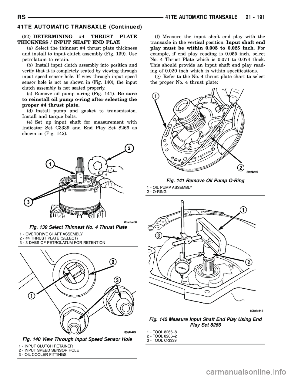
(52)DETERMINING #4 THRUST PLATE
THICKNESS / INPUT SHAFT END PLAY:
(a) Select the thinnest #4 thrust plate thickness
and install to input clutch assembly (Fig. 139). Use
petrolatum to retain.
(b)
Install input clutch assembly into position and
verify that it is completely seated by viewing through
input speed sensor hole. If view through input speed
sensor hole is not as shown in (Fig. 140), the input
clutch assembly is not seated properly.
(c) Remove oil pump o-ring (Fig. 141).Be sure
to reinstall oil pump o-ring after selecting the
proper #4 thrust plate.
(d) Install pump and gasket to transmission.
Install and torque bolts.
(e) Set up input shaft for measurement with
Indicator Set C3339 and End Play Set 8266 as
shown in (Fig. 142).(f) Measure the input shaft end play with the
transaxle in the vertical position.Input shaft end
play must be within 0.005 to 0.025 inch.For
example, if end play reading is 0.055 inch, select
No. 4 Thrust Plate which is 0.071 to 0.074 thick.
This should provide an input shaft end play read-
ing of 0.020 inch which is within specifications.
(g) Refer to the No. 4 thrust plate chart to select
the proper No. 4 thrust plate:
Fig. 139 Select Thinnest No. 4 Thrust Plate
1 - OVERDRIVE SHAFT ASSEMBLY
2 - #4 THRUST PLATE (SELECT)
3 - 3 DABS OF PETROLATUM FOR RETENTION
Fig. 140 View Through Input Speed Sensor Hole
1 - INPUT CLUTCH RETAINER
2 - INPUT SPEED SENSOR HOLE
3 - OIL COOLER FITTINGS
Fig. 141 Remove Oil Pump O-Ring
1 - OIL PUMP ASSEMBLY
2 - O-RING
Fig. 142 Measure Input Shaft End Play Using End
Play Set 8266
1 - TOOL 8266±8
2 - TOOL 8266±2
3 - TOOL C-3339
RS41TE AUTOMATIC TRANSAXLE21 - 191
41TE AUTOMATIC TRANSAXLE (Continued)
Page 1653 of 2339
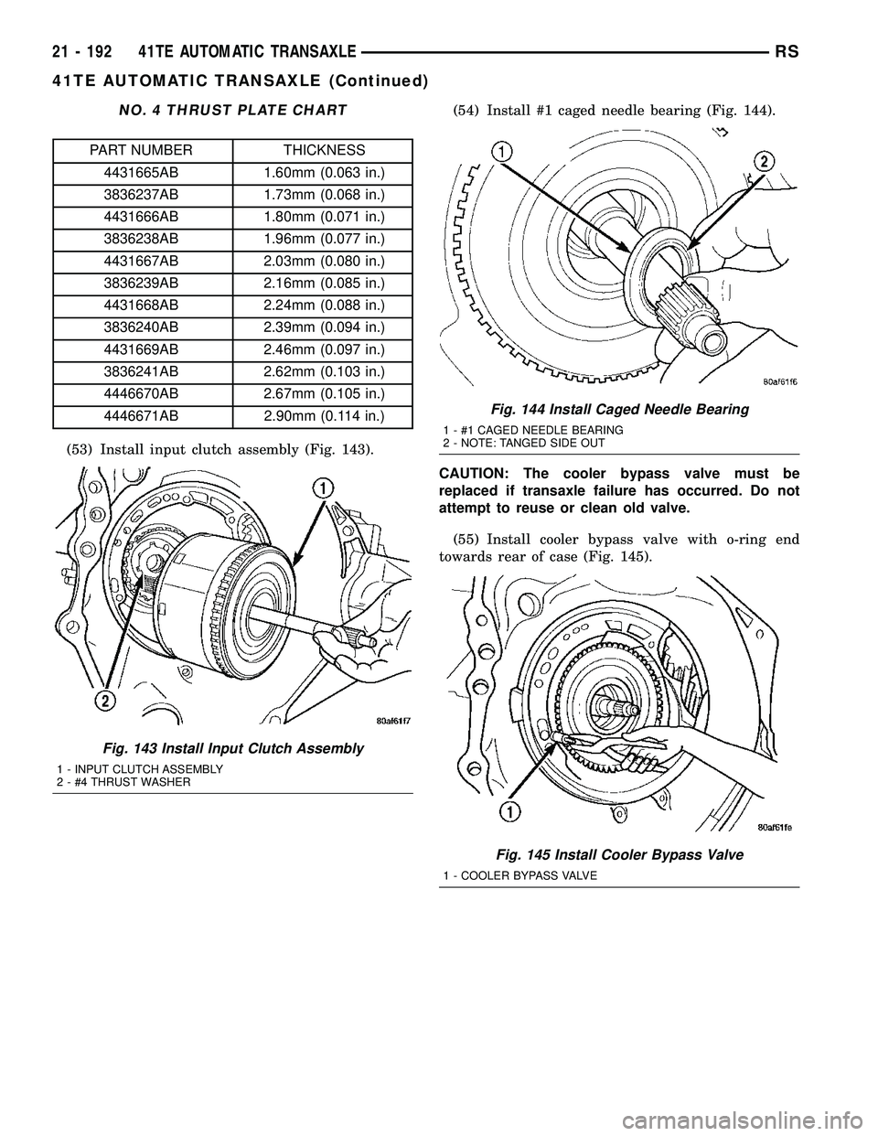
NO. 4 THRUST PLATE CHART
PART NUMBER THICKNESS
4431665AB 1.60mm (0.063 in.)
3836237AB 1.73mm (0.068 in.)
4431666AB 1.80mm (0.071 in.)
3836238AB 1.96mm (0.077 in.)
4431667AB 2.03mm (0.080 in.)
3836239AB 2.16mm (0.085 in.)
4431668AB 2.24mm (0.088 in.)
3836240AB 2.39mm (0.094 in.)
4431669AB 2.46mm (0.097 in.)
3836241AB 2.62mm (0.103 in.)
4446670AB 2.67mm (0.105 in.)
4446671AB 2.90mm (0.114 in.)
(53) Install input clutch assembly (Fig. 143).(54) Install #1 caged needle bearing (Fig. 144).
CAUTION: The cooler bypass valve must be
replaced if transaxle failure has occurred. Do not
attempt to reuse or clean old valve.
(55) Install cooler bypass valve with o-ring end
towards rear of case (Fig. 145).
Fig. 143 Install Input Clutch Assembly
1 - INPUT CLUTCH ASSEMBLY
2 - #4 THRUST WASHER
Fig. 144 Install Caged Needle Bearing
1 - #1 CAGED NEEDLE BEARING
2 - NOTE: TANGED SIDE OUT
Fig. 145 Install Cooler Bypass Valve
1 - COOLER BYPASS VALVE
21 - 192 41TE AUTOMATIC TRANSAXLERS
41TE AUTOMATIC TRANSAXLE (Continued)
Page 1657 of 2339

(69) Install and tighten solenoid/pressure switch
assembly-to-transaxle case bolts to 12 N´m (110 in.
lbs.) (Fig. 158).
(70) Install and torque input and output speed
sensors to case to 27 N´m (20 ft. lbs.).
INSTALLATION
NOTE: If transaxle assembly has been replaced or
overhauled (clutch and/or seal replacement), it is
necessary to perfrom the ªQuick-Learnº procedure.
(Refer to 8 - ELECTRICAL/ELECTRONIC CONTROL
MODULES/TRANSMISSION CONTROL MODULE -
STANDARD PROCEDURE)
(1) Using a transmission jack and a helper, posi-
tion transaxle assembly to engine. Install and torque
bellhousing bolts to 95 N´m (70 ft. lbs.).
(2) Install upper mount assembly to transaxle and
torque bolts to 54 N´m (40 ft. lbs.) (Fig. 159).
(3) Raise engine/transaxle assembly into position.
Install and torque upper mount-to-bracket thru-bolt
to 75 N´m (55 ft. lbs.) (Fig. 159).
(4) Remove transmission jack and screw jack.
(5) Secure left wheelhouse splash shield.
(6) Install torque converter-to-drive plate bolts and
torque to 88 N´m (65 ft. lbs.)
(7) Install inspection cover.
(8) Install lateral bending brace.
(9) Install starter motor.
(10) Install front mount/bracket assembly.
(11) Align and install rear mount bracket-to-case
bolts by hand (Fig. 160). Torque horizontal bolt to
102 N´m (75 ft. lbs.).(12) AWD models: Install power transfer unit.
(Refer to 21 - TRANSMISSION/TRANSAXLE/
POWER TRANSFER UNIT - INSTALLATION)
(13) Install left and right halfshaft assemblies.
(Refer to 3 - DIFFERENTIAL & DRIVELINE/HALF
SHAFT - INSTALLATION)
(14) Install front wheel/tire assemblies.
(15) Lower vehicle.
(16) Torque remaining rear mount bracket-to-tran-
saxle vertical bolts (Fig. 160) to 102 N´m (75 ft. lbs.).
(17) Install transaxle upper bellhousing-to-block
bolts and torque to 95 N´m (70 ft. lbs.).
(18) Install and connect crank position sensor (if
equipped).
(19) Connect gearshift cable to upper mount
bracket and transaxle manual valve lever (Fig. 161).
(20) Connect solenoid/pressure switch assembly
(Fig. 162).
(21) Connect transmission range sensor connector
(Fig. 162).
(22) Connect input and output speed sensor con-
nectors (Fig. 162).
(23) Remove plugs and connect transaxle oil cooler
lines. (Refer to 7 - COOLING/TRANSMISSION -
STANDARD PROCEDURE)
(24) Remove plug and Install fluid level indicator/
tube assembly.
Fig. 158 Solenoid Pack-to-Transaxle Bolts
1 - BOLTS
2 - SOLENOID AND PRESSURE SWITCH ASSEMBLY
Fig. 159 Left Mount to Bracket and Transaxle
1 - BOLT - BRACKET TO FRAME RAIL 68 N´m (50 ft. lbs.)
2 - BOLT - MOUNT TO RAIL THRU 75 N´m (55 ft. lbs.)
3 - BOLT - LEFT MOUNT TO TRANSAXLE 54 N´m (40 ft. lbs.)
4 - TRANSAXLE
5 - MOUNT - LEFT
6 - BRACKET - LEFT MOUNT
21 - 196 41TE AUTOMATIC TRANSAXLERS
41TE AUTOMATIC TRANSAXLE (Continued)
Page 1672 of 2339
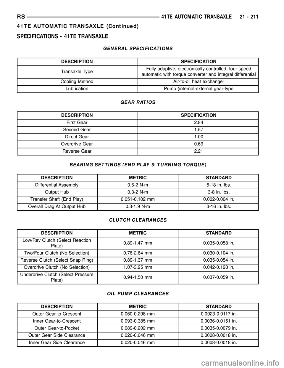
SPECIFICATIONS - 41TE TRANSAXLE
GENERAL SPECIFICATIONS
DESCRIPTION SPECIFICATION
Transaxle TypeFully adaptive, electronically controlled, four speed
automatic with torque converter and integral differential
Cooling Method Air-to-oil heat exchanger
Lubrication Pump (internal-external gear-type
GEAR RATIOS
DESCRIPTION SPECIFICATION
First Gear 2.84
Second Gear 1.57
Direct Gear 1.00
Overdrive Gear 0.69
Reverse Gear 2.21
BEARING SETTINGS (END PLAY & TURNING TORQUE)
DESCRIPTION METRIC STANDARD
Differential Assembly 0.6-2 N´m 5-18 in. lbs.
Output Hub 0.3-2 N´m 3-8 in. lbs.
Transfer Shaft (End Play) 0.051-0.102 mm 0.002-0.004 in.
Overall Drag At Output Hub 0.3-1.9 N´m 3-16 in. lbs.
CLUTCH CLEARANCES
DESCRIPTION METRIC STANDARD
Low/Rev Clutch (Select Reaction
Plate)0.89-1.47 mm 0.035-0.058 in.
Two/Four Clutch (No Selection) 0.76-2.64 mm 0.030-0.104 in.
Reverse Clutch (Select Snap Ring) 0.89-1.37 mm 0.035-0.054 in.
Overdrive Clutch (No Selection) 1.07-3.25 mm 0.042-0.128 in.
Underdrive Clutch (Select Pressure
Plate)0.94-1.50 mm 0.037-0.059 in.
OIL PUMP CLEARANCES
DESCRIPTION METRIC STANDARD
Outer Gear-to-Crescent 0.060-0.298 mm 0.0023-0.0117 in.
Inner Gear-to-Crescent 0.093-0.385 mm 0.0036-0.0151 in.
Outer Gear-to-Pocket 0.089-0.202 mm 0.0035-0.0079 in.
Outer Gear Side Clearance 0.020-0.046 mm 0.0008-0.0018 in.
Inner Gear Side Clearance 0.020-0.046 mm 0.0008-0.0018 in.
RS41TE AUTOMATIC TRANSAXLE21 - 211
41TE AUTOMATIC TRANSAXLE (Continued)
Page 1673 of 2339
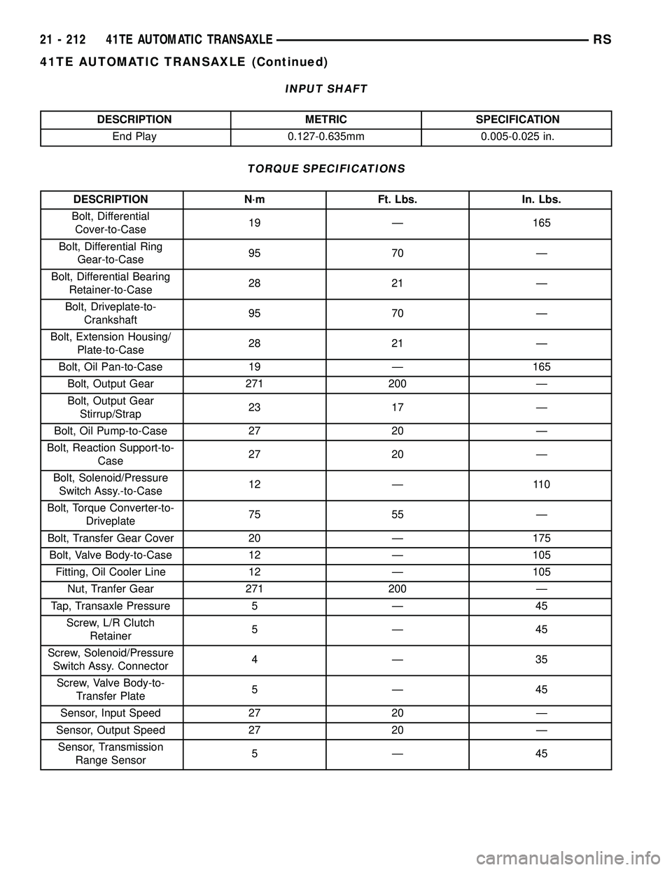
INPUT SHAFT
DESCRIPTION METRIC SPECIFICATION
End Play 0.127-0.635mm 0.005-0.025 in.
TORQUE SPECIFICATIONS
DESCRIPTION N´m Ft. Lbs. In. Lbs.
Bolt, Differential
Cover-to-Case19 Ð 165
Bolt, Differential Ring
Gear-to-Case95 70 Ð
Bolt, Differential Bearing
Retainer-to-Case28 21 Ð
Bolt, Driveplate-to-
Crankshaft95 70 Ð
Bolt, Extension Housing/
Plate-to-Case28 21 Ð
Bolt, Oil Pan-to-Case 19 Ð 165
Bolt, Output Gear 271 200 Ð
Bolt, Output Gear
Stirrup/Strap23 17 Ð
Bolt, Oil Pump-to-Case 27 20 Ð
Bolt, Reaction Support-to-
Case27 20 Ð
Bolt, Solenoid/Pressure
Switch Assy.-to-Case12 Ð 110
Bolt, Torque Converter-to-
Driveplate75 55 Ð
Bolt, Transfer Gear Cover 20 Ð 175
Bolt, Valve Body-to-Case 12 Ð 105
Fitting, Oil Cooler Line 12 Ð 105
Nut, Tranfer Gear 271 200 Ð
Tap, Transaxle Pressure 5 Ð 45
Screw, L/R Clutch
Retainer5Ð45
Screw, Solenoid/Pressure
Switch Assy. Connector4Ð35
Screw, Valve Body-to-
Transfer Plate5Ð45
Sensor, Input Speed 27 20 Ð
Sensor, Output Speed 27 20 Ð
Sensor, Transmission
Range Sensor5Ð45
21 - 212 41TE AUTOMATIC TRANSAXLERS
41TE AUTOMATIC TRANSAXLE (Continued)
Page 1678 of 2339
Installer 6261
Tip 6268
Remover/Installer 6301
Remover/Installer 6302
Installer 6536-A
Puller 7794-A
End Play Socket Set 8266
Input Clutch Pressure Fixture 8391
RS41TE AUTOMATIC TRANSAXLE21 - 217
41TE AUTOMATIC TRANSAXLE (Continued)
Page 1679 of 2339
ACCUMULATOR
DESCRIPTION
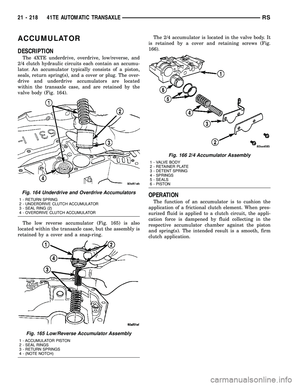
The 4XTE underdrive, overdrive, low/reverse, and
2/4 clutch hydraulic circuits each contain an accumu-
lator. An accumulator typically consists of a piston,
seals, return spring(s), and a cover or plug. The over-
drive and underdrive accumulators are located
within the transaxle case, and are retained by the
valve body (Fig. 164).
The low reverse accumulator (Fig. 165) is also
located within the transaxle case, but the assembly is
retained by a cover and a snap-ring.The 2/4 accumulator is located in the valve body. It
is retained by a cover and retaining screws (Fig.
166).
OPERATION
The function of an accumulator is to cushion the
application of a frictional clutch element. When pres-
surized fluid is applied to a clutch circuit, the appli-
cation force is dampened by fluid collecting in the
respective accumulator chamber against the piston
and spring(s). The intended result is a smooth, firm
clutch application.
Fig. 164 Underdrive and Overdrive Accumulators
1 - RETURN SPRING
2 - UNDERDRIVE CLUTCH ACCUMULATOR
3 - SEAL RING (2)
4 - OVERDRIVE CLUTCH ACCUMULATOR
Fig. 165 Low/Reverse Accumulator Assembly
1 - ACCUMULATOR PISTON
2 - SEAL RINGS
3 - RETURN SPRINGS
4 - (NOTE NOTCH)
Fig. 166 2/4 Accumulator Assembly
1 - VALVE BODY
2 - RETAINER PLATE
3 - DETENT SPRING
4 - SPRINGS
5 - SEALS
6 - PISTON
21 - 218 41TE AUTOMATIC TRANSAXLERS