Page 1564 of 2339
(21) Install the OD clutch pack (Fig. 236).
(22) Install OD pressure plate waved snap ring
(Fig. 237).(23) Install the OD/Reverse pressure plate with
large step down (towards OD clutch pack) (Fig. 238).
(24) Install OD pressure plate flat snap ring (Fig.
239) (Fig. 240).
Fig. 236 Install Overdrive Clutch Pack
1 - CLUTCH DISC
2 - CLUTCH PLATE
Fig. 237 Install Waved Snap Ring
1 - OVERDRIVE PRESSURE PLATE WAVED SNAP RING
2 - SCREWDRIVER
Fig. 238 OD/Reverse Reaction Plate
1 - OVERDRIVE/REVERSE PRESSURE PLATE
2 - (STEP SIDE DOWN)
Fig. 239 Install Flat Snap Ring
1 - ARBOR PRESS RAM
2 - TOOL 5059A
3 - FLAT SNAP RING
RS40TE AUTOMATIC TRANSAXLE21 - 103
INPUT CLUTCH ASSEMBLY (Continued)
Page 1565 of 2339
Fig. 240 Overdrive Clutch Assembly
1 - SNAP RING
2 - OD/REVERSE PRESSURE PLATE
3 - SNAP RING (WAVE)4 - CLUTCH DISC (3)
5 - CLUTCH STEEL (2)
6 - INPUT CLUTCH ASSEMBLY
21 - 104 40TE AUTOMATIC TRANSAXLERS
INPUT CLUTCH ASSEMBLY (Continued)
Page 1566 of 2339

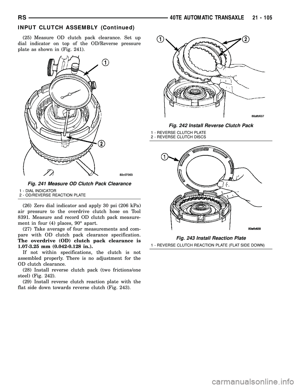
(25) Measure OD clutch pack clearance. Set up
dial indicator on top of the OD/Reverse pressure
plate as shown in (Fig. 241).
(26) Zero dial indicator and apply 30 psi (206 kPa)
air pressure to the overdrive clutch hose on Tool
8391. Measure and record OD clutch pack measure-
ment in four (4) places, 90É apart.
(27) Take average of four measurements and com-
pare with OD clutch pack clearance specification.
The overdrive (OD) clutch pack clearance is
1.07-3.25 mm (0.042-0.128 in.).
If not within specifications, the clutch is not
assembled properly. There is no adjustment for the
OD clutch clearance.
(28) Install reverse clutch pack (two frictions/one
steel) (Fig. 242).
(29) Install reverse clutch reaction plate with the
flat side down towards reverse clutch (Fig. 243).
Fig. 241 Measure OD Clutch Pack Clearance
1 - DIAL INDICATOR
2 - OD/REVERSE REACTION PLATE
Fig. 242 Install Reverse Clutch Pack
1 - REVERSE CLUTCH PLATE
2 - REVERSE CLUTCH DISCS
Fig. 243 Install Reaction Plate
1 - REVERSE CLUTCH REACTION PLATE (FLAT SIDE DOWN)
RS40TE AUTOMATIC TRANSAXLE21 - 105
INPUT CLUTCH ASSEMBLY (Continued)
Page 1567 of 2339
(30) Tap reaction plate down to allow installation
of the reverse clutch snap ring. Install reverse clutch
snap ring (Fig. 244) (Fig. 245).(31) Pry up reverse reaction plate to seat against
snap ring (Fig. 246).
Fig. 245 Reverse Clutch Assembly
1 - SNAP RING
2 - REACTION PLATE
3 - CLUTCH DISC (2)4 - CLUTCH PLATE (1)
5 - INPUT CLUTCH ASSEMBLY
Fig. 244 Install Reverse Clutch Snap Ring
1 - REVERSE CLUTCH SNAP RING (SELECT)
2 - SCREWDRIVER
3 - REVERSE CLUTCH REACTION PLATE
Fig. 246 Pry Up Reaction Plate
1 - SCREWDRIVER
2 - SNAP RING
3 - SCREWDRIVER
4 - MUST RAISE REVERSE REACTION PLATE TO RAISE SNAP
RING
21 - 106 40TE AUTOMATIC TRANSAXLERS
INPUT CLUTCH ASSEMBLY (Continued)
Page 1568 of 2339

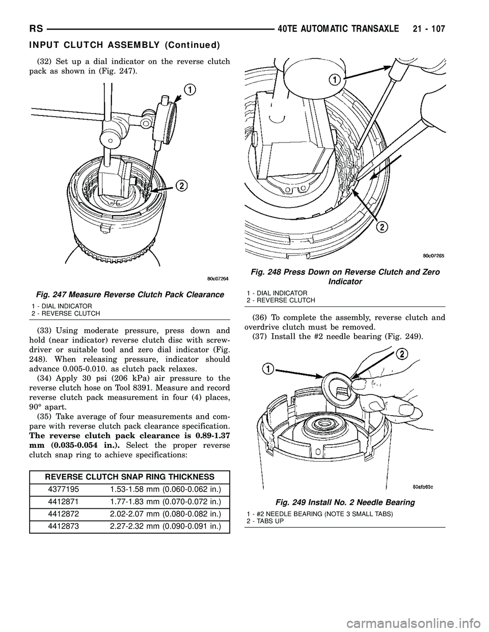
(32) Set up a dial indicator on the reverse clutch
pack as shown in (Fig. 247).
(33) Using moderate pressure, press down and
hold (near indicator) reverse clutch disc with screw-
driver or suitable tool and zero dial indicator (Fig.
248). When releasing pressure, indicator should
advance 0.005-0.010. as clutch pack relaxes.
(34) Apply 30 psi (206 kPa) air pressure to the
reverse clutch hose on Tool 8391. Measure and record
reverse clutch pack measurement in four (4) places,
90É apart.
(35) Take average of four measurements and com-
pare with reverse clutch pack clearance specification.
The reverse clutch pack clearance is 0.89-1.37
mm (0.035-0.054 in.).Select the proper reverse
clutch snap ring to achieve specifications:
REVERSE CLUTCH SNAP RING THICKNESS
4377195 1.53-1.58 mm (0.060-0.062 in.)
4412871 1.77-1.83 mm (0.070-0.072 in.)
4412872 2.02-2.07 mm (0.080-0.082 in.)
4412873 2.27-2.32 mm (0.090-0.091 in.)(36) To complete the assembly, reverse clutch and
overdrive clutch must be removed.
(37) Install the #2 needle bearing (Fig. 249).
Fig. 247 Measure Reverse Clutch Pack Clearance
1 - DIAL INDICATOR
2 - REVERSE CLUTCH
Fig. 248 Press Down on Reverse Clutch and Zero
Indicator
1 - DIAL INDICATOR
2 - REVERSE CLUTCH
Fig. 249 Install No. 2 Needle Bearing
1 - #2 NEEDLE BEARING (NOTE 3 SMALL TABS)
2 - TABS UP
RS40TE AUTOMATIC TRANSAXLE21 - 107
INPUT CLUTCH ASSEMBLY (Continued)
Page 1569 of 2339

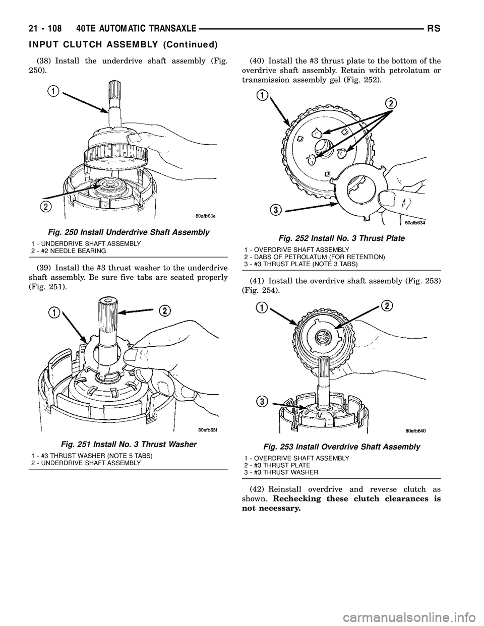
(38) Install the underdrive shaft assembly (Fig.
250).
(39) Install the #3 thrust washer to the underdrive
shaft assembly. Be sure five tabs are seated properly
(Fig. 251).(40) Install the #3 thrust plate to the bottom of the
overdrive shaft assembly. Retain with petrolatum or
transmission assembly gel (Fig. 252).
(41) Install the overdrive shaft assembly (Fig. 253)
(Fig. 254).
(42) Reinstall overdrive and reverse clutch as
shown.Rechecking these clutch clearances is
not necessary.
Fig. 250 Install Underdrive Shaft Assembly
1 - UNDERDRIVE SHAFT ASSEMBLY
2 - #2 NEEDLE BEARING
Fig. 251 Install No. 3 Thrust Washer
1 - #3 THRUST WASHER (NOTE 5 TABS)
2 - UNDERDRIVE SHAFT ASSEMBLY
Fig. 252 Install No. 3 Thrust Plate
1 - OVERDRIVE SHAFT ASSEMBLY
2 - DABS OF PETROLATUM (FOR RETENTION)
3 - #3 THRUST PLATE (NOTE 3 TABS)
Fig. 253 Install Overdrive Shaft Assembly
1 - OVERDRIVE SHAFT ASSEMBLY
2 - #3 THRUST PLATE
3 - #3 THRUST WASHER
21 - 108 40TE AUTOMATIC TRANSAXLERS
INPUT CLUTCH ASSEMBLY (Continued)
Page 1570 of 2339
Fig. 254 Overdrive/Underdrive Shafts
1 - OVERDRIVE SHAFT
2 - #3 THRUST PLATE (3 TABS)
3 - #3 THRUST WASHER (5 TABS)4 - UNDERDRIVE SHAFT
5 - #2 NEEDLE BEARING (3 TABS)
6 - INPUT CLUTCH ASSEMBLY
RS40TE AUTOMATIC TRANSAXLE21 - 109
INPUT CLUTCH ASSEMBLY (Continued)
Page 1573 of 2339

(8) Position an appropriate piece of Plastigage
across both pump gears.
(9) Align the Plastigage to a flat area on the reac-
tion shaft support housing.
(10) Install the reaction shaft to the pump housing
(Fig. 256). Tighten the bolts to 27 N´m (20 ft. lbs.).
(11) Remove bolts and carefully separate the hous-
ings. Measure the Plastigage following the instruc-
tions supplied.
(12) Clearance between both gear end faces and
the reaction shaft support should be 0.020-0.046 mm
(0.0008-0.0018 in.).
ASSEMBLY
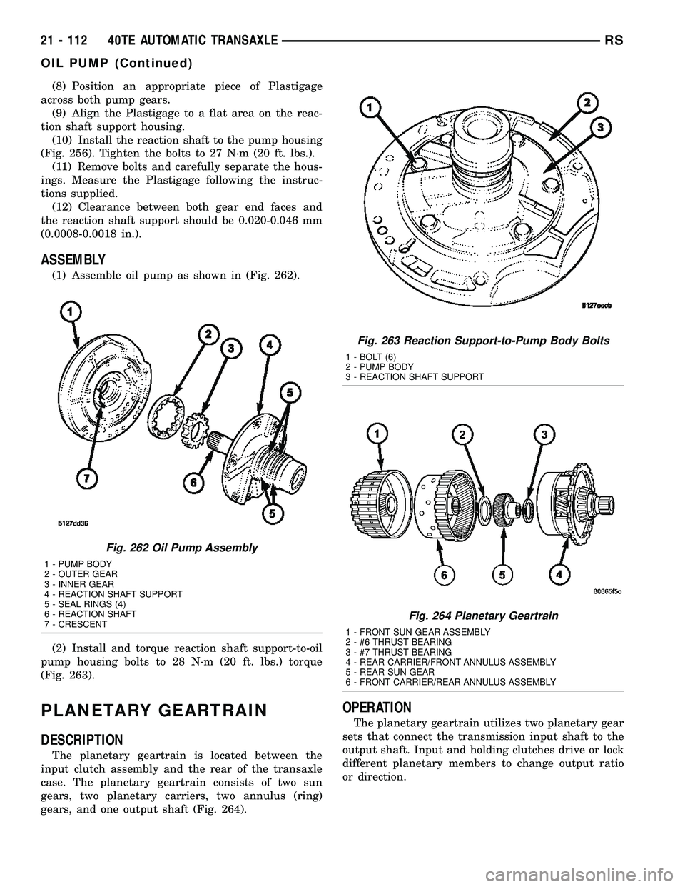
(1) Assemble oil pump as shown in (Fig. 262).
(2) Install and torque reaction shaft support-to-oil
pump housing bolts to 28 N´m (20 ft. lbs.) torque
(Fig. 263).
PLANETARY GEARTRAIN
DESCRIPTION
The planetary geartrain is located between the
input clutch assembly and the rear of the transaxle
case. The planetary geartrain consists of two sun
gears, two planetary carriers, two annulus (ring)
gears, and one output shaft (Fig. 264).
OPERATION
The planetary geartrain utilizes two planetary gear
sets that connect the transmission input shaft to the
output shaft. Input and holding clutches drive or lock
different planetary members to change output ratio
or direction.
Fig. 262 Oil Pump Assembly
1 - PUMP BODY
2 - OUTER GEAR
3 - INNER GEAR
4 - REACTION SHAFT SUPPORT
5 - SEAL RINGS (4)
6 - REACTION SHAFT
7 - CRESCENT
Fig. 263 Reaction Support-to-Pump Body Bolts
1 - BOLT (6)
2 - PUMP BODY
3 - REACTION SHAFT SUPPORT
Fig. 264 Planetary Geartrain
1 - FRONT SUN GEAR ASSEMBLY
2 - #6 THRUST BEARING
3 - #7 THRUST BEARING
4 - REAR CARRIER/FRONT ANNULUS ASSEMBLY
5 - REAR SUN GEAR
6 - FRONT CARRIER/REAR ANNULUS ASSEMBLY
21 - 112 40TE AUTOMATIC TRANSAXLERS
OIL PUMP (Continued)