Page 1490 of 2339
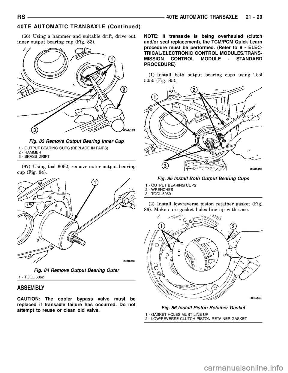
(66) Using a hammer and suitable drift, drive out
inner output bearing cup (Fig. 83).
(67) Using tool 6062, remove outer output bearing
cup (Fig. 84).
ASSEMBLY
CAUTION: The cooler bypass valve must be
replaced if transaxle failure has occurred. Do not
attempt to reuse or clean old valve.NOTE: If transaxle is being overhauled (clutch
and/or seal replacement), the TCM/PCM Quick Learn
procedure must be performed. (Refer to 8 - ELEC-
TRICAL/ELECTRONIC CONTROL MODULES/TRANS-
MISSION CONTROL MODULE - STANDARD
PROCEDURE)
(1) Install both output bearing cups using Tool
5050 (Fig. 85).
(2) Install low/reverse piston retainer gasket (Fig.
86). Make sure gasket holes line up with case.
Fig. 83 Remove Output Bearing Inner Cup
1 - OUTPUT BEARING CUPS (REPLACE IN PAIRS)
2 - HAMMER
3 - BRASS DRIFT
Fig. 84 Remove Output Bearing Outer
1 - TOOL 6062
Fig. 85 Install Both Output Bearing Cups
1 - OUTPUT BEARING CUPS
2 - WRENCHES
3 - TOOL 5050
Fig. 86 Install Piston Retainer Gasket
1 - GASKET HOLES MUST LINE UP
2 - LOW/REVERSE CLUTCH PISTON RETAINER GASKET
RS40TE AUTOMATIC TRANSAXLE21-29
40TE AUTOMATIC TRANSAXLE (Continued)
Page 1491 of 2339
(3) Install low/reverse piston retainer (Fig. 87).
(4) Install low/reverse piston retainer-to-case bolts
(Fig. 88) and torque to 5 N´m (45 in. lbs.).
NOTE: The Low/Reverse Clutch Piston has bonded
seals which are not individually serviceable. Seal
replacement requires replacement of the piston
assembly.(5) Install low/reverse clutch piston (Fig. 89).
(6) Assemble park guide bracket assembly (Fig.
91) (Fig. 90).
Fig. 87 Install Piston Retainer
1 - LOW/REVERSE CLUTCH PISTON RETAINER
2 - GASKET
Fig. 88 Install Piston Retainer-to-Case Screws
1 - LOW/REVERSE CLUTCH PISTON RETAINER
2 - SCREWDRIVER
3 - TORX-LOC SCREWS
Fig. 89 Install Low/Reverse Clutch Piston
1 - LOW/REVERSE CLUTCH PISTON
2 - BONDED SEAL
3 - BONDED SEAL
Fig. 90 Guide Bracket Disassembled
1 - ANTIRATCHET SPRING
2 - GUIDE BRACKET
3 - SPLIT SLEEVE
4 - SPACER
5-PAWL
6 - STEPPED SPACER
21 - 30 40TE AUTOMATIC TRANSAXLERS
40TE AUTOMATIC TRANSAXLE (Continued)
Page 1493 of 2339
(10) Install low/reverse spring compressor into
position (Fig. 95). Compress low/reverse piston and
install snap ring as shown in (Fig. 96).(11) Install rear carrier bearing cone using Tool
6053 (Fig. 97).
(12) Install rear carrier assembly to transaxle case
(Fig. 98).
Fig. 95 Compressor Tool in Use
1 - LOW/REVERSE CLUTCH RETURN SPRING
2 - SNAP RING (INSTALL AS SHOWN)
3 - TOOL 6057
4 - TOOL 5059
5 - TOOL 5058±3
Fig. 96 Install Snap Ring
1 - SNAP RING OPENING MUST BE BETWEEN SPRING LEVERS
(AS SHOWN)
2 - SNAP RING PLIERS
3 - TOOL 6057
Fig. 97 Install Rear Carrier Bearing Cone
1 - ARBOR PRESS RAM
2 - TOOL 6053
3 - NEW BEARING CONE
4 - REAR CARRIER ASSEMBLY
Fig. 98 Install Rear Carrier Assembly
1 - REAR CARRIER ASSEMBLY
21 - 32 40TE AUTOMATIC TRANSAXLERS
40TE AUTOMATIC TRANSAXLE (Continued)
Page 1503 of 2339
(38) Install low/reverse clutch pack (Fig. 123).
Leave uppermost disc out until snap ring is installed.
(39) Install low/reverse reaction plate flat snap
ring (Fig. 124).(40) Install remaining low/reverse clutch disc (Fig.
125).
(41) Install low/reverse reaction plate with flat
side up (Fig. 126).
Fig. 123 Install Low/Reverse Clutch
1 - CLUTCH PLATE
2 - CLUTCH DISC
Fig. 124 Install Low/Reverse Reaction Plate Snap
Ring
1 - SCREWDRIVER
2 - LOW/REVERSE REACTION PLATE FLAT SNAP RING
3 - DO NOT SCRATCH CLUTCH PLATE
Fig. 125 Install One Disc
1 - ONE DISC FROM LOW/REVERSE CLUTCH
Fig. 126 Install Low/Reverse Reaction Plate
1 - LOW/REVERSE REACTION PLATE (FLAT SIDE UP)
21 - 42 40TE AUTOMATIC TRANSAXLERS
40TE AUTOMATIC TRANSAXLE (Continued)
Page 1504 of 2339
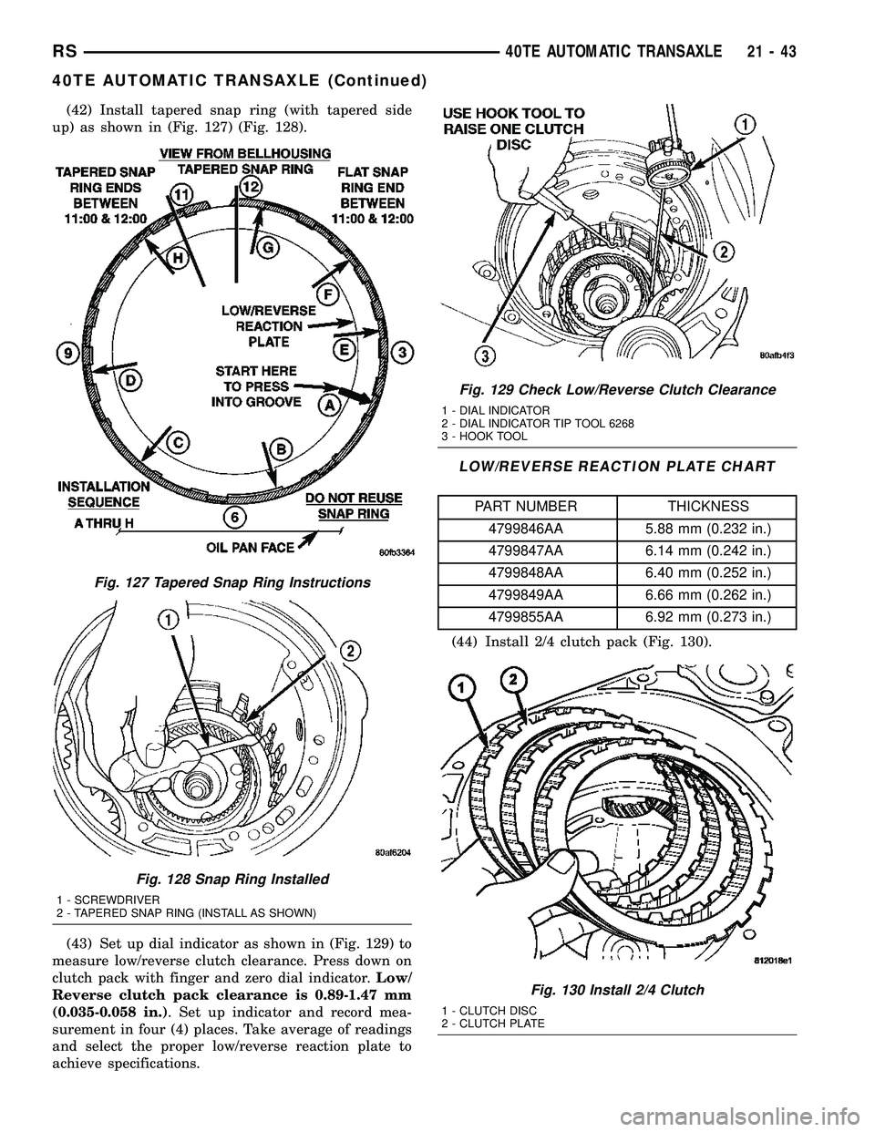
(42) Install tapered snap ring (with tapered side
up) as shown in (Fig. 127) (Fig. 128).
(43) Set up dial indicator as shown in (Fig. 129) to
measure low/reverse clutch clearance. Press down on
clutch pack with finger and zero dial indicator.Low/
Reverse clutch pack clearance is 0.89-1.47 mm
(0.035-0.058 in.). Set up indicator and record mea-
surement in four (4) places. Take average of readings
and select the proper low/reverse reaction plate to
achieve specifications.
LOW/REVERSE REACTION PLATE CHART
PART NUMBER THICKNESS
4799846AA 5.88 mm (0.232 in.)
4799847AA 6.14 mm (0.242 in.)
4799848AA 6.40 mm (0.252 in.)
4799849AA 6.66 mm (0.262 in.)
4799855AA 6.92 mm (0.273 in.)
(44) Install 2/4 clutch pack (Fig. 130).
Fig. 127 Tapered Snap Ring Instructions
Fig. 128 Snap Ring Installed
1 - SCREWDRIVER
2 - TAPERED SNAP RING (INSTALL AS SHOWN)
Fig. 129 Check Low/Reverse Clutch Clearance
1 - DIAL INDICATOR
2 - DIAL INDICATOR TIP TOOL 6268
3 - HOOK TOOL
Fig. 130 Install 2/4 Clutch
1 - CLUTCH DISC
2 - CLUTCH PLATE
RS40TE AUTOMATIC TRANSAXLE21-43
40TE AUTOMATIC TRANSAXLE (Continued)
Page 1505 of 2339
NOTE: The 2/4 Clutch Piston has bonded seals
which are not individually serviceable. Seal replace-
ment requires replacement of the piston assembly.
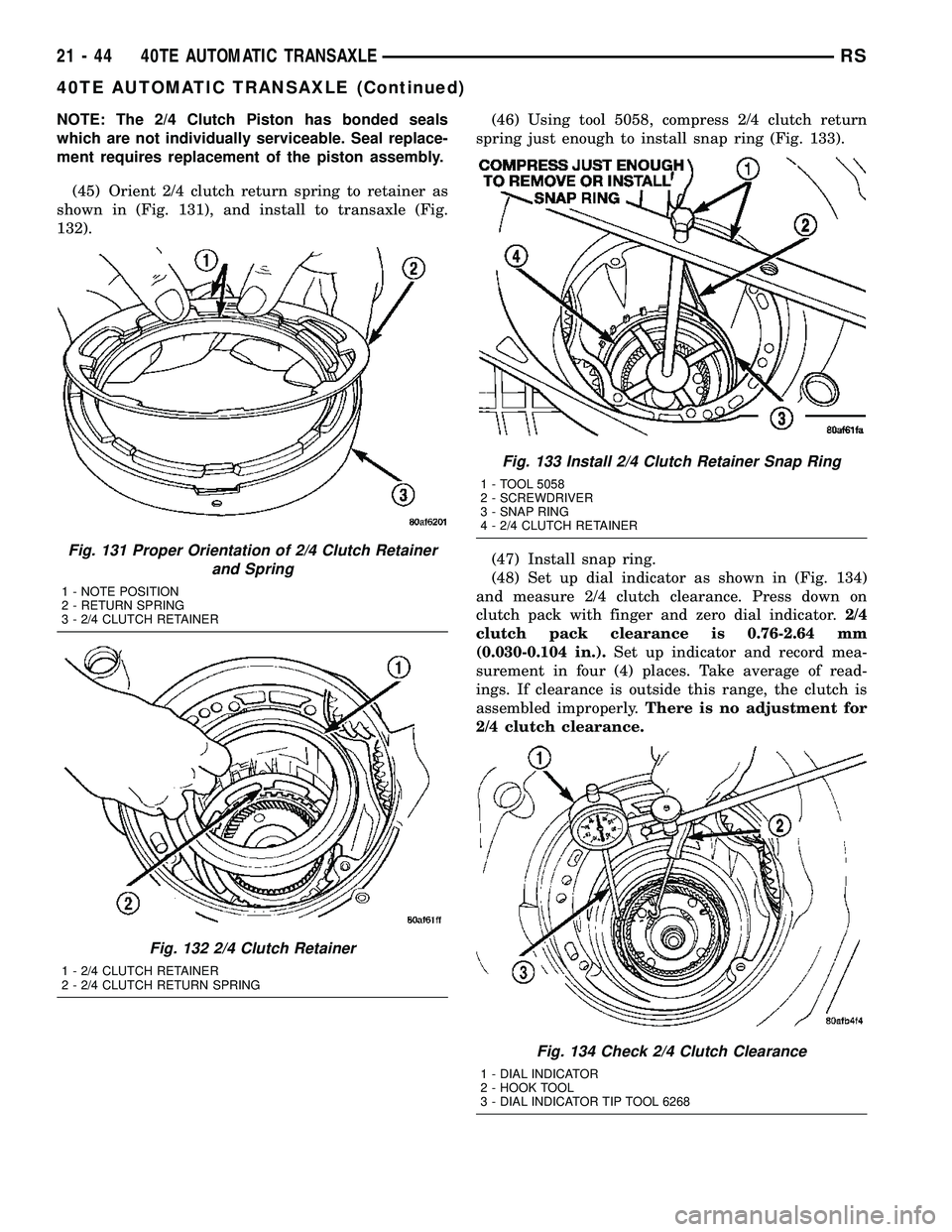
(45) Orient 2/4 clutch return spring to retainer as
shown in (Fig. 131), and install to transaxle (Fig.
132).(46) Using tool 5058, compress 2/4 clutch return
spring just enough to install snap ring (Fig. 133).
(47) Install snap ring.
(48) Set up dial indicator as shown in (Fig. 134)
and measure 2/4 clutch clearance. Press down on
clutch pack with finger and zero dial indicator.2/4
clutch pack clearance is 0.76-2.64 mm
(0.030-0.104 in.).Set up indicator and record mea-
surement in four (4) places. Take average of read-
ings. If clearance is outside this range, the clutch is
assembled improperly.There is no adjustment for
2/4 clutch clearance.
Fig. 131 Proper Orientation of 2/4 Clutch Retainer
and Spring
1 - NOTE POSITION
2 - RETURN SPRING
3 - 2/4 CLUTCH RETAINER
Fig. 132 2/4 Clutch Retainer
1 - 2/4 CLUTCH RETAINER
2 - 2/4 CLUTCH RETURN SPRING
Fig. 133 Install 2/4 Clutch Retainer Snap Ring
1 - TOOL 5058
2 - SCREWDRIVER
3 - SNAP RING
4 - 2/4 CLUTCH RETAINER
Fig. 134 Check 2/4 Clutch Clearance
1 - DIAL INDICATOR
2 - HOOK TOOL
3 - DIAL INDICATOR TIP TOOL 6268
21 - 44 40TE AUTOMATIC TRANSAXLERS
40TE AUTOMATIC TRANSAXLE (Continued)
Page 1507 of 2339
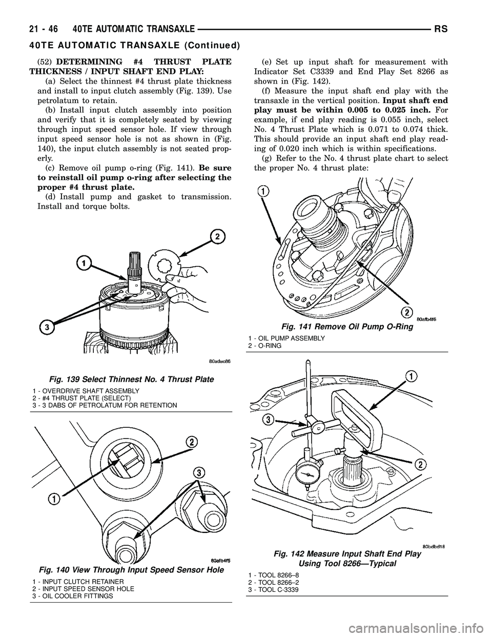
(52)DETERMINING #4 THRUST PLATE
THICKNESS / INPUT SHAFT END PLAY:
(a) Select the thinnest #4 thrust plate thickness
and install to input clutch assembly (Fig. 139). Use
petrolatum to retain.
(b) Install input clutch assembly into position
and verify that it is completely seated by viewing
through input speed sensor hole. If view through
input speed sensor hole is not as shown in (Fig.
140), the input clutch assembly is not seated prop-
erly.
(c) Remove oil pump o-ring (Fig. 141).Be sure
to reinstall oil pump o-ring after selecting the
proper #4 thrust plate.
(d) Install pump and gasket to transmission.
Install and torque bolts.(e) Set up input shaft for measurement with
Indicator Set C3339 and End Play Set 8266 as
shown in (Fig. 142).
(f) Measure the input shaft end play with the
transaxle in the vertical position.Input shaft end
play must be within 0.005 to 0.025 inch.For
example, if end play reading is 0.055 inch, select
No. 4 Thrust Plate which is 0.071 to 0.074 thick.
This should provide an input shaft end play read-
ing of 0.020 inch which is within specifications.
(g) Refer to the No. 4 thrust plate chart to select
the proper No. 4 thrust plate:
Fig. 139 Select Thinnest No. 4 Thrust Plate
1 - OVERDRIVE SHAFT ASSEMBLY
2 - #4 THRUST PLATE (SELECT)
3 - 3 DABS OF PETROLATUM FOR RETENTION
Fig. 140 View Through Input Speed Sensor Hole
1 - INPUT CLUTCH RETAINER
2 - INPUT SPEED SENSOR HOLE
3 - OIL COOLER FITTINGS
Fig. 141 Remove Oil Pump O-Ring
1 - OIL PUMP ASSEMBLY
2 - O-RING
Fig. 142 Measure Input Shaft End Play
Using Tool 8266ÐTypical
1 - TOOL 8266±8
2 - TOOL 8266±2
3 - TOOL C-3339
21 - 46 40TE AUTOMATIC TRANSAXLERS
40TE AUTOMATIC TRANSAXLE (Continued)
Page 1508 of 2339
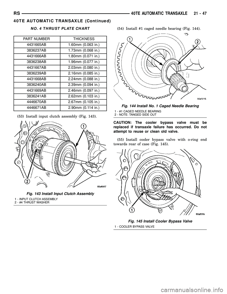
NO. 4 THRUST PLATE CHART
PART NUMBER THICKNESS
4431665AB 1.60mm (0.063 in.)
3836237AB 1.73mm (0.068 in.)
4431666AB 1.80mm (0.071 in.)
3836238AB 1.96mm (0.077 in.)
4431667AB 2.03mm (0.080 in.)
3836239AB 2.16mm (0.085 in.)
4431668AB 2.24mm (0.088 in.)
3836240AB 2.39mm (0.094 in.)
4431669AB 2.46mm (0.097 in.)
3836241AB 2.62mm (0.103 in.)
4446670AB 2.67mm (0.105 in.)
4446671AB 2.90mm (0.114 in.)
(53) Install input clutch assembly (Fig. 143).(54) Install #1 caged needle bearing (Fig. 144).
CAUTION: The cooler bypass valve must be
replaced if transaxle failure has occurred. Do not
attempt to reuse or clean old valve.
(55) Install cooler bypass valve with o-ring end
towards rear of case (Fig. 145).
Fig. 143 Install Input Clutch Assembly
1 - INPUT CLUTCH ASSEMBLY
2 - #4 THRUST WASHER
Fig. 144 Install No. 1 Caged Needle Bearing
1 - #1 CAGED NEEDLE BEARING
2 - NOTE: TANGED SIDE OUT
Fig. 145 Install Cooler Bypass Valve
1 - COOLER BYPASS VALVE
RS40TE AUTOMATIC TRANSAXLE21-47
40TE AUTOMATIC TRANSAXLE (Continued)