Page 41 of 78
PERIODIC MAINTENANCE AND MINOR REPAIR
6-10
1
2
3
4
5
6
7
8
9
for several minutes while checking
it for oil leakage. If oil is leaking, im-
mediately turn the engine off and
check for the cause.
10. Turn the engine off, and then
check the oil level and correct it if
necessary.
EAU32401
Cleaning the air filter element
The air filter element should be cleaned
at the intervals specified in the periodic
maintenance and lubrication chart.
Clean the air filter element more fre-
quently if you are riding in unusually
wet or dusty areas.
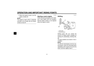
1. Remove the air filter case by re-
moving the bolts and loosening the
clamp screw.
2. Remove the air filter case cover by
removing the screws.3. Remove the air filter element by
removing the screws.
4. Lightly tap the air filter element to
remove most of the dust and dirt,
and then blow the remaining dirt
1. Bolt
2. Clamp screw
1
2
1. Screw
1. Air filter element
2. Screw
1
1
1
2(×2)
Page 42 of 78

PERIODIC MAINTENANCE AND MINOR REPAIR
6-11
2
3
4
5
67
8
9
out with compressed air as shown.
If the air filter element is damaged,
replace it.
5. Install the air filter element by in-
serting it into the air filter case,
then installing the screws.
CAUTION:
ECA10480
�
Make sure that the air filter ele-
ment is properly seated in the
air filter case.
�
The engine should never be op-
erated without the air filter ele-
ment installed, otherwise the
piston(s) and/or cylinder(s) may
become excessively worn.
6. Install the air filter case cover by in-stalling the screws.
7. Install the air filter case by install-
ing the bolts, then tightening the
clamp screw.
EAU21280
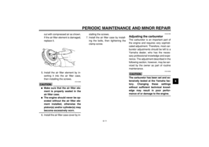
Adjusting the carburetor
The carburetor is an important part of
the engine and requires very sophisti-
cated adjustment. Therefore, most car-
buretor adjustments should be left to a
Yamaha dealer, who has the neces-
sary professional knowledge and expe-
rience. The adjustment described in the
following section, however, may be ser-
viced by the owner as part of routine
maintenance.
CAUTION:
ECA10550
The carburetor has been set and ex-
tensively tested at the Yamaha fac-
tory. Changing these settings
without sufficient technical knowl-
edge may result in poor perfor-
mance of or damage to the engine.
Page 43 of 78

PERIODIC MAINTENANCE AND MINOR REPAIR
6-12
1
2
3
4
5
6
7
8
9
EAU21340
Adjusting the engine idling
speed
The engine idling speed must be
checked and, if necessary, adjusted as
follows at the intervals specified in the
periodic maintenance and lubrication
chart.
The engine should be warm before
making this adjustment.
NOTE:
�
The engine is warm when it quickly
responds to the throttle.
�
A diagnostic tachometer is needed
to make this adjustment.
1. Attach the tachometer to the spark
plug lead.
2. Check the engine idling speed
and, if necessary, adjust it to spec-
ification by turning the throttle stop
screw. To increase the engine
idling speed, turn the screw in di-
rection (a). To decrease the en-
gine idling speed, turn the screw in
direction (b).
NOTE:
If the specified idling speed cannot be
obtained as described above, have a
Yamaha dealer make the adjustment.
EAU21380
Adjusting the throttle cable
free play
The throttle cable free play should mea-
sure 3.0–5.0 mm (0.12–0.20 in) at the
throttle grip. Periodically check the
throttle cable free play and, if neces-
sary, have a Yamaha dealer adjust it.
1. Throttle stop screw
Engine idling speed:
1250–1450 r/min
1
(a) (b)
1. Throttle cable free play
1
Page 44 of 78

PERIODIC MAINTENANCE AND MINOR REPAIR
6-13
2
3
4
5
67
8
9
EAU21400
Adjusting the valve clearance
The valve clearance changes with use,
resulting in improper air-fuel mixture
and/or engine noise. To prevent this
from occurring, the valve clearance
must be adjusted by a Yamaha dealer
at the intervals specified in the periodic
maintenance and lubrication chart.
EAU21540
Tires
To maximize the performance, durabil-
ity, and safe operation of your motorcy-
cle, note the following points regarding
the specified tires.
Tire air pressure
The tire air pressure should be checked
and, if necessary, adjusted before each
ride.
WARNING
EWA10500
�
The tire air pressure must be
checked and adjusted on cold
tires (i.e., when the temperature
of the tires equals the ambient
temperature).
�
The tire air pressure must be ad-
justed in accordance with the
riding speed and with the total
weight of rider, passenger, car-
go, and accessories approved
for this model.
WARNING
EWA11020
Because loading has an enormous
impact on the handling, braking,
performance and safety characteris-
tics of your motorcycle, you should
keep the following precautions in
mind.
�
NEVER OVERLOAD THE MO-
TORCYCLE! Operation of an Tire air pressure (measured on
cold tires):
0.0–90.0 kg (0–198 lb) :
Front:
175 kPa (25 psi) (1.75 kgf/cm
2
)
Rear:
200 kPa (29 psi) (2.00 kgf/cm
2
)
90.0–183.0 kg (198–404 lb) :
Front:
175 kPa (25 psi) (1.75 kgf/cm
2
)
Rear:
200 kPa (29 psi) (2.00 kgf/cm
2
)
Maximum load*:
183.0 kg (404 lb)
* Total weight of rider, passenger,
cargo and accessories
Page 45 of 78

PERIODIC MAINTENANCE AND MINOR REPAIR
6-14
1
2
3
4
5
6
7
8
9overloaded motorcycle may re-
sult in tire damage, loss of con-
trol, or severe injury. Make sure
that the total weight of rider,
passenger, cargo, and accesso-
ries does not exceed the speci-
fied maximum load for the
vehicle.
�
Do not carry along loosely
packed items, which can shift
during a ride.
�
Securely pack the heaviest
items close to the center of the
motorcycle and distribute the
weight evenly on both sides.
�
Adjust the suspension and tire
air pressure with regard to the
load.
�
Check the tire condition and air
pressure before each ride.Tire inspection
The tires must be checked before each
ride. If the center tread depth reaches
the specified limit, if the tire has a nail or
glass fragments in it, or if the sidewall is
cracked, have a Yamaha dealer re-
place the tire immediately.
NOTE:
The tire tread depth limits may differ
from country to country. Always comply
with the local regulations.
Tire information
This motorcycle is equipped with tube
tires.
WARNING
EWA10460
�
The front and rear tires should
be of the same make and de-
sign, otherwise the handling
characteristics of the vehicle
cannot be guaranteed.
�
After extensive tests, only the
tires listed below have been
approved for this model by
Yamaha Motor Co., Ltd.
1. Tire tread depth
2. Tire sidewall
Minimum tire tread depth (front
and rear):
1.6 mm
12
Page 46 of 78

PERIODIC MAINTENANCE AND MINOR REPAIR
6-15
2
3
4
5
67
8
9
WARNING
EWA10570
�
Have a Yamaha dealer replace
excessively worn tires. Besides
being illegal, operating the mo-
torcycle with excessively worn
tires decreases riding stability
and can lead to loss of control.
�
The replacement of all wheel-
and brake-related parts, includ-
ing the tires, should be left to a
Yamaha dealer, who has the
necessary professional knowl-edge and experience.
�
It is not recommended to patch
a punctured tube. If unavoid-
able, however, patch the tube
very carefully and replace it as
soon as possible with a
high-quality product.
EAU21940
Spoke wheels
To maximize the performance, durabil-
ity, and safe operation of your motorcy-
cle, note the following points regarding
the specified wheels.
�
The wheel rims should be checked
for cracks, bends or warpage, and
the spokes for looseness or dam-
age before each ride. If any dam-
age is found, have a Yamaha
dealer replace the wheel. Do not
attempt even the smallest repair to
the wheel. A deformed or cracked
wheel must be replaced.
�
The wheel should be balanced
whenever either the tire or wheel
has been changed or replaced. An
unbalanced wheel can result in
poor performance, adverse han-
dling characteristics, and a short-
ened tire life.
�
Ride at moderate speeds after
changing a tire since the tire sur-
face must first be “broken in” for it
to develop its optimal characteris-
tics.
Front tire:
Size:
80/100-18M/C 47P
Manufacturer/model:
CHENG SHIN/C-916
IRC/MARBELLA NF27
Rear tire:
Size:
130/90-15M/C 66P
Manufacturer/model:
CHENG SHIN/C-915
IRC/MARBELLA NR31
Page 47 of 78
 as
shown.")
PERIODIC MAINTENANCE AND MINOR REPAIR
6-16
1
2
3
4
5
6
7
8
9
EAU22040
Adjusting the clutch lever free
play
The clutch lever free play should mea-
sure 5.0–10.0 mm (0.20–0.39 in) as
shown. Periodically check the clutch le-
ver free play and, if necessary, adjust it
as follows.
1. Loosen the locknut at the clutch le-
ver.
2. To increase the clutch lever free
play, turn the adjusting bolt in di-
rection (a). To decrease the clutch
lever free play, turn the adjusting
bolt in direction (b).3. If the specified clutch lever free
play could be obtained as de-
scribed above, tighten the locknut
and skip the rest of the procedure,
otherwise proceed as follows.
4. Fully turn the adjusting bolt at the
clutch lever in direction (a) to loos-
en the clutch cable.
5. Loosen the locknut at the crank-
case.
6. To increase the clutch lever free
play, turn the adjusting nut in direc-
tion (a). To decrease the clutch le-
ver free play, turn the adjusting nut
in direction (b).7. Tighten the locknut at the clutch le-
ver and the crankcase.
1. Locknut (clutch lever)
2. Adjusting bolt
3. Clutch lever free play
12
3
(a) (b)
1. Locknut (crankcase)
2. Adjusting nut
2
1
(a)
(b)
Page 48 of 78
 as
shown. Perio")
PERIODIC MAINTENANCE AND MINOR REPAIR
6-17
2
3
4
5
67
8
9
EAU22091
Adjusting the brake lever free
play
The brake lever free play should mea-
sure 5.0–8.0 mm (0.20–0.31 in) as
shown. Periodically check the brake le-
ver free play and, if necessary, adjust it
as follows.
1. Loosen the locknut at the brake le-
ver.
2. To increase the brake lever free
play, turn the adjusting bolt in di-
rection (a). To decrease the brake
lever free play, turn the adjusting
bolt in direction (b).3. Tighten the locknut.
WARNING
EWA10630
�
After adjusting the brake lever
free play, check the free play
and make sure that the brake is
working properly.
�
A soft or spongy feeling in the
brake lever can indicate the
presence of air in the hydraulic
system. If there is air in the hy-
draulic system, have a Yamaha
dealer bleed the system before
operating the motorcycle. Air in
the hydraulic system will dimin-
ish the braking performance,
which may result in loss of con-
trol and an accident.
EAU22201
Adjusting the brake pedal
position and free play
WARNING
EWA10670
It is advisable to have a Yamaha
dealer make these adjustments.
Brake pedal position
The top of the brake pedal should be
positioned approximately 76.6 mm
(3.02 in) above the top of the footrest as
shown. Periodically check the brake
pedal position and, if necessary, adjust
it as follows.
1. Loosen the locknut at the brake
1. Locknut
2. Adjusting bolt
3. Brake lever free play
2 1
3
(b)
(a)
1. Footrest
2. Brake pedal position
1
2