Page 33 of 78

PERIODIC MAINTENANCE AND MINOR REPAIR
6-2
1
2
3
4
5
6
7
8
9
EAU17710
Periodic maintenance and lubrication chart
NOTE:
�
The annual checks must be performed every year, except if a kilometer-based maintenance is performed in-
stead.
�
From 30,000 km, repeat the maintenance intervals starting from 6,000 km.
�
Items marked with an asterisk should be performed by a Yamaha dealer as they require special tools, data and technical
skills.
NO. ITEM CHECK OR MAINTENANCE JOBODOMETER READING (
×
1,000 km)
ANNUAL
CHECK
1 6 12 18 24
1*
Fuel line
�
Check fuel hoses and vacuum hose for cracks or dam-
age.
√
√
√
√
√
2
Spark plugs
�
Check condition.
�
Clean and regap.
√
√
�
Replace.
√
√
3*
Valves
�
Check valve clearance.
�
Adjust.
√
√
√
√
4
Air filter element
�
Clean.
√
√
�
Replace.
√
√
5
Clutch
�
Check operation.
�
Adjust.
√
√
√
√
√
6*
Front brake
�
Check operation, fluid level and vehicle for fluid leak-
age. (See NOTE following this chart.)
√
√
√
√
√
√
�
Replace brake pads. Whenever worn to the limit
7*
Rear brake
�
Check operation and adjust brake pedal free play.
√
√
√
√
√
√
�
Replace brake shoes. Whenever worn to the limit
8*
Brake hose
�
Check for cracks or damage.
√
√
√
√
√
�
Replace. (See NOTE following this chart.) Every 4 years
Page 34 of 78

PERIODIC MAINTENANCE AND MINOR REPAIR
6-3
2
3
4
5
67
8
9
9*
Wheels
�
Check runout, spoke tightness and for damage.
�
Tighten spokes if necessary.
√
√
√
√
10
*
Tires
�
Check tread depth and for damage.
�
Replace if necessary.
�
Check air pressure.
�
Correct if necessary.
√
√
√
√
√
11
*
Wheel bearings
�
Check bearing for looseness or damage.
√
√
√
√
12
*
Swingarm
�
Check operation and for excessive play.
√
√
√
√
�
Lubricate with molybdenum disulfide grease. Every 24,000 km
13
Drive chain
�
Check chain slack.
�
Make sure that the rear wheel is properly aligned.
�
Clean and lubricate.Every 1,000 km and after washing the motorcycle or
riding in the rain
14
*
Steering bearings
�
Check bearing play and steering for roughness.
√
√
√
√
√
�
Lubricate with lithium-soap-based grease. Every 24,000 km
15
*
Chassis fasteners
�
Make sure that all nuts, bolts and screws are properly
tightened.
√
√
√
√
√
16
Sidestand
�
Check operation.
�
Lubricate.
√
√
√
√
√
17
*
Sidestand switch
�
Check operation.
√
√
√
√
√
√
18
*
Front fork
�
Check operation and for oil leakage.
√
√
√
√
19
*
Shock absorber assem-
blies
�
Check operation and shock absorbers for oil leakage.
√
√
√
√
20
*
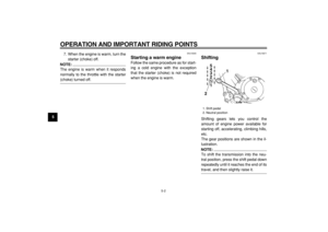
Carburetor
�
Check starter (choke) operation.
�
Adjust engine idling speed.
√
√
√
√
√
√
21
Engine oil
�
Change.
�
Check oil level and vehicle for oil leakage.
√
√
√
√
√
√
22
Engine oil filter element
�
Replace.
√
√
√
23
*
Front and rear brake
switches
�
Check operation.
√
√
√
√ √ √ NO. ITEM CHECK OR MAINTENANCE JOBODOMETER READING (× 1,000 km)
ANNUAL
CHECK
1 6 12 18 24
Page 35 of 78
PERIODIC MAINTENANCE AND MINOR REPAIR
6-4
1
2
3
4
5
6
7
8
9
EAU18660
NOTE:
�
The air filter needs more frequent service if you are riding in unusually wet or dusty areas.
�
Hydraulic brake service
�
Regularly check and, if necessary, correct the brake fluid level.
�
Every two years replace the internal components of the brake master cylinder and caliper, and change the brake fluid.
�
Replace the brake hoses every four years and if cracked or damaged.
24
Moving parts and cables
�
Lubricate.
√
√
√
√
√
25
*
Lights, signals and
switches
�
Check operation.
�
Adjust headlight beam.
√
√
√
√
√
√
NO. ITEM CHECK OR MAINTENANCE JOBODOMETER READING (
×
1,000 km)
ANNUAL
CHECK
1 6 12 18 24
Page 36 of 78
PERIODIC MAINTENANCE AND MINOR REPAIR
6-5
2
3
4
5
67
8
9
EAU18770
Removing and installing
panels
The panels shown above need to be re-
moved to perform some of the mainte-
nance jobs described in this chapter.Refer to this section each time a panel
needs to be removed and installed.
EAU32471
Panel A
To remove the panel
1. Remove the bolt.
2. Pull the rear of the panel out, and
then slide the panel forward to re-
lease it in the front.To install the panel
1. Secure the front of the panel, and
then push the rear of the panel in.
2. Install the bolt.
Panel B
To remove the panel1. Slide the panel lock cover open, in-
sert the key into the lock, and then
turn it 1/4 turn clockwise.
1. Panel A
1. Panel B
11
1. Bolt
1
Page 37 of 78

PERIODIC MAINTENANCE AND MINOR REPAIR
6-6
1
2
3
4
5
6
7
8
9
2. Pull the rear of the panel out with
the key inserted in the lock, and
then slide the panel forward to re-
lease it in the front.
To install the panel
1. Secure the front of the panel, andthen push the rear of the panel in
with the key inserted in the lock.
2. Turn the key counterclockwise to
the original position, remove it, and
then close the panel lock cover.
EAU19543
Checking the spark plugs
The spark plugs are important engine
components, which are easy to check.
Since heat and deposits will cause any
spark plug to slowly erode, the spark
plugs should be removed and checked
in accordance with the periodic mainte-
nance and lubrication chart. In addition,
the condition of the spark plugs can re-
veal the condition of the engine.
To remove a spark plug
1. Remove the spark plug cap.
2. Remove the spark plug as shown,
with the spark plug wrench includ-
ed in the owner’s tool kit.
1. Lock cover
2. Unlock.
1
2
1. Spark plug cap
1
Page 38 of 78

PERIODIC MAINTENANCE AND MINOR REPAIR
6-7
2
3
4
5
67
8
9 To check the spark plugs
1. Check that the porcelain insulator
around the center electrode on
each spark plug is a medi-
um-to-light tan (the ideal color
when the vehicle is ridden normal-
ly).
2. Check that all spark plugs installed
in the engine have the same color.
NOTE:
If any spark plug shows a distinctly dif-
ferent color, the engine could be defec-
tive. Do not attempt to diagnose such
problems yourself. Instead, have a
Yamaha dealer check the vehicle.
3. Check each spark plug for elec-trode erosion and excessive car-
bon or other deposits, and replace
it if necessary.
To install a spark plug
1. Measure the spark plug gap with a
wire thickness gauge and, if nec-
essary, adjust the gap to specifica-
tion.
2. Clean the surface of the spark pluggasket and its mating surface, and
then wipe off any grime from the
spark plug threads.
3. Install the spark plug with the
spark plug wrench, and then tight-
en it to the specified torque.
NOTE:
If a torque wrench is not available when
installing a spark plug, a good estimate
of the correct torque is 1/4–1/2 turn
past finger tight. However, the spark
plug should be tightened to the speci-
fied torque as soon as possible.
4. Install the spark plug cap.
1. Spark plug wrench
1
Specified spark plug:
NGK/CR7HSA
DENSO/U22FSR-U
1. Spark plug gap
Spark plug gap:
0.6–0.7 mm (0.024–0.028 in)
1
Tightening torque:
Spark plug:
12.5 Nm (1.25 m·kgf, 9 ft·lbf)
Page 39 of 78

PERIODIC MAINTENANCE AND MINOR REPAIR
6-8
1
2
3
4
5
6
7
8
9
EAU19751
Engine oil and oil filter
element
The engine oil level should be checked
before each ride. In addition, the oil
must be changed and the oil filter ele-
ment replaced at the intervals specified
in the periodic maintenance and lubri-
cation chart.
To check the engine oil level
1. Place the vehicle on a level sur-
face and hold it in an upright posi-
tion.
NOTE:
Make sure that the vehicle is positioned
straight up when checking the oil level.
A slight tilt to the side can result in a
false reading.
2. Start the engine, warm it up for
several minutes, and then turn it
off.
3. Wait a few minutes until the oil set-
tles, and then check the oil level
through the check window located
at the bottom-right side of the
crankcase.
NOTE:
The engine oil should be between the
minimum and maximum level marks.
4. If the engine oil is below the mini-
mum level mark, add sufficient oil
of the recommended type to raise
it to the correct level.
To change the engine oil (with or
without oil filter element replace-
ment)
1. Start the engine, warm it up for
several minutes, and then turn it
off.
2. Place an oil pan under the engineto collect the used oil.
3. Remove the engine oil filler cap
and drain bolt to drain the oil from
the crankcase.
NOTE:
Skip steps 4–6 if the oil filter element is
1. Engine oil level check window
2. Maximum level mark
3. Minimum level mark
2
1
3
1. Engine oil filler cap
1. Engine oil drain bolt
11
Page 40 of 78

PERIODIC MAINTENANCE AND MINOR REPAIR
6-9
2
3
4
5
67
8
9
not being replaced.
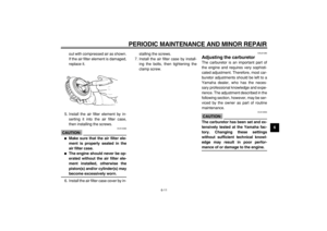
4. Remove the oil filter element cover
by removing the bolts.
5. Remove and replace the oil filter
element and O-ring.6. Install the oil filter element cover by
installing the bolts, then tightening
them to the specified torque.
NOTE:
Make sure that the O-ring is properly
seated.
7. Install the engine oil drain bolt, and
then tighten it to the specified
torque.
8. Add the specified amount of the
recommended engine oil, and then
install and tighten the oil filler cap.
CAUTION:
ECA11620
�
In order to prevent clutch slip-
page (since the engine oil also
lubricates the clutch), do not
mix any chemical additives. Do
not use oils with a diesel speci-
fication of “CD” or oils of a high-
er quality than specified. In
addition, do not use oils labeled
“ENERGY CONSERVING II” or
higher.
�
Make sure that no foreign mate-
rial enters the crankcase.
9. Start the engine, and then let it idle
1. Bolt
1. Oil filter element
2. O-ring
1(×3)
2
1
Tightening torque:
Oil filter element cover bolt:
10 Nm (1.0 m·kgf, 7.2 ft·lbf)
Tightening torque:
Engine oil drain bolt:
34 Nm (3.4 m·kgf, 24.5 ft·lbf)
Recommended engine oil:
See page 8-1.
Oil quantity:
With oil filter element replace-
ment:
1.60 L (1.69 US qt)
(1.41 Imp.qt)
Without oil filter element re-
placement:
1.40 L (1.48 US qt)
(1.23 Imp.qt)