Page 2349 of 2870
4AT-37
AUTOMATIC TRANSMISSION
Line Pressure Test
6) Check for duty ratio changes by opening and
closing the throttle valve using the Subaru Select
Monitor.
NON-TURBO MODEL
TURBO MODEL
Standard line pressure
Range posi-
tionLine pres-
sure duty
ratio (%)Accelera-
tion open-
ing angle
(%)Line pressure
kPa (kg/cm
2, psi)
2
(HOLD
switch ON)5100
(Fully
opens)1,130 — 1,275
(11.5 — 13.0,
164 — 185)
R5100
(Fully
opens)1,520 — 1,716
(15.5 — 17.5,
220 — 249)
D950
(Fully
closed)300 — 410
(3.1 — 4.2,
44 — 60)
Standard line pressure
Range posi-
tionLine pres-
sure duty
ratio (%)Accelera-
tion open-
ing angle
(%)Line pressure
kPa (kg/cm
2, psi)
2
(HOLD
switch ON)(2.5 — 3.5)100
(Fully
opens)1,400 — 1,700
(14.3 — 17.3,
203 — 247)
R (1.5 — 2.5)100
(Fully
opens)1,600 — 1,900
(16.3 — 19.4,
232 — 276)
D (3.5 — 4.5)0
(Fully
closed)500 — 800
(5.1 — 8.2,
73 — 116)
Page 2350 of 2870
4AT-38
AUTOMATIC TRANSMISSION
Transfer Clutch Pressure Test
8. Transfer Clutch Pressure
Test
A: INSPECTION
Check the transfer clutch pressure in accordance
with the following steps in the same manner as with
line pressure.
Test.>
ST 498897700 OIL PRESSURE ADAPTER
SET
ST 498575400 OIL PRESSURE GAUGE
ASSYNOTE:
Before setting in FWD mode, install the spare fuse
on FWD mode switch.
NOTE:
If the oil pressure is not produced or if it does not
change in the AWD mode, the transfer duty sole-
noid or transfer valve assembly may be malfunc-
tioning. If the oil pressure is produced in the FWD
mode, the problem is similar to that in the AWD
mode.
STANDARD TRANSFER CLUTCH PRESSURE:
NON-TURBO MODEL
TURBO MODEL
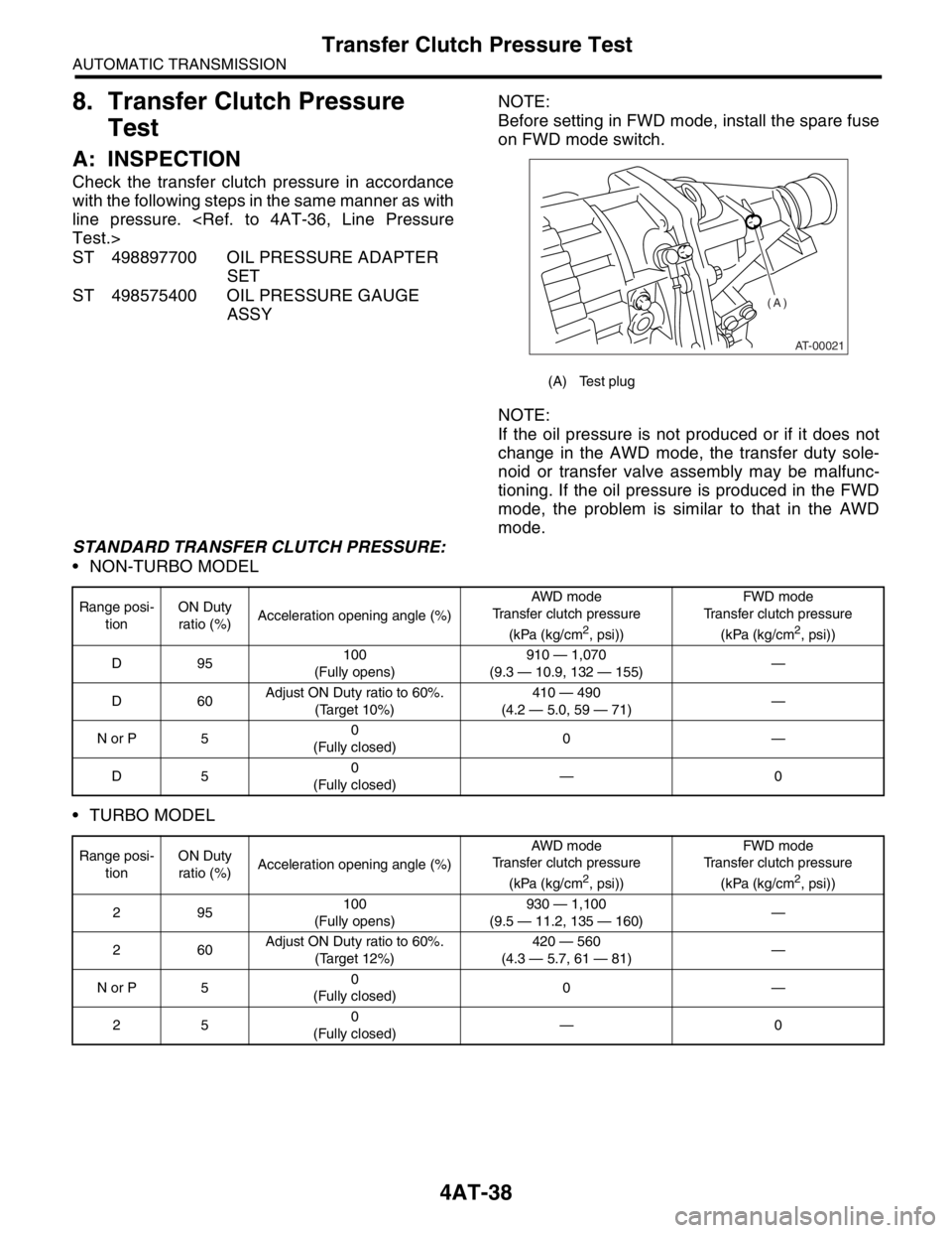
(A) Test plug
AT-00021
(A)
Range posi-
tionON Duty
ratio (%)Acceleration opening angle (%)AWD m od e
Transfer clutch pressure
(kPa (kg/cm
2, psi))FWD mode
Transfer clutch pressure
(kPa (kg/cm2, psi))
D95100
(Fully opens)910 — 1,070
(9.3 — 10.9, 132 — 155)—
D60Adjust ON Duty ratio to 60%.
(Target 10%)410 — 490
(4.2 — 5.0, 59 — 71)—
N or P 50
(Fully closed)0—
D50
(Fully closed)—0
Range posi-
tionON Duty
ratio (%)Acceleration opening angle (%)AWD m od e
Transfer clutch pressure
(kPa (kg/cm
2, psi))FWD mode
Transfer clutch pressure
(kPa (kg/cm2, psi))
295100
(Fully opens)930 — 1,100
(9.5 — 11.2, 135 — 160)—
260Adjust ON Duty ratio to 60%.
(Target 12%)420 — 560
(4.3 — 5.7, 61 — 81)—
N or P 50
(Fully closed)0—
250
(Fully closed)—0
Page 2351 of 2870
4AT-39
AUTOMATIC TRANSMISSION
Automatic Transmission Assembly
9. Automatic Transmission As-
sembly
A: REMOVAL
1) Set the vehicle on a lift.
2) Fully open the front hood and support with the
hood stay.
3) Disconnect the ground cable from battery.
4) Remove the resonator chamber. (Non-turbo
model)
Chamber.>
5) Remove the air cleaner case or air intake cham-
ber. (Non-turbo model).
Case.>
6) Remove the intercooler. (Turbo model)
er.>
7) Remove the air cleaner case stay. (Non-turbo
model).
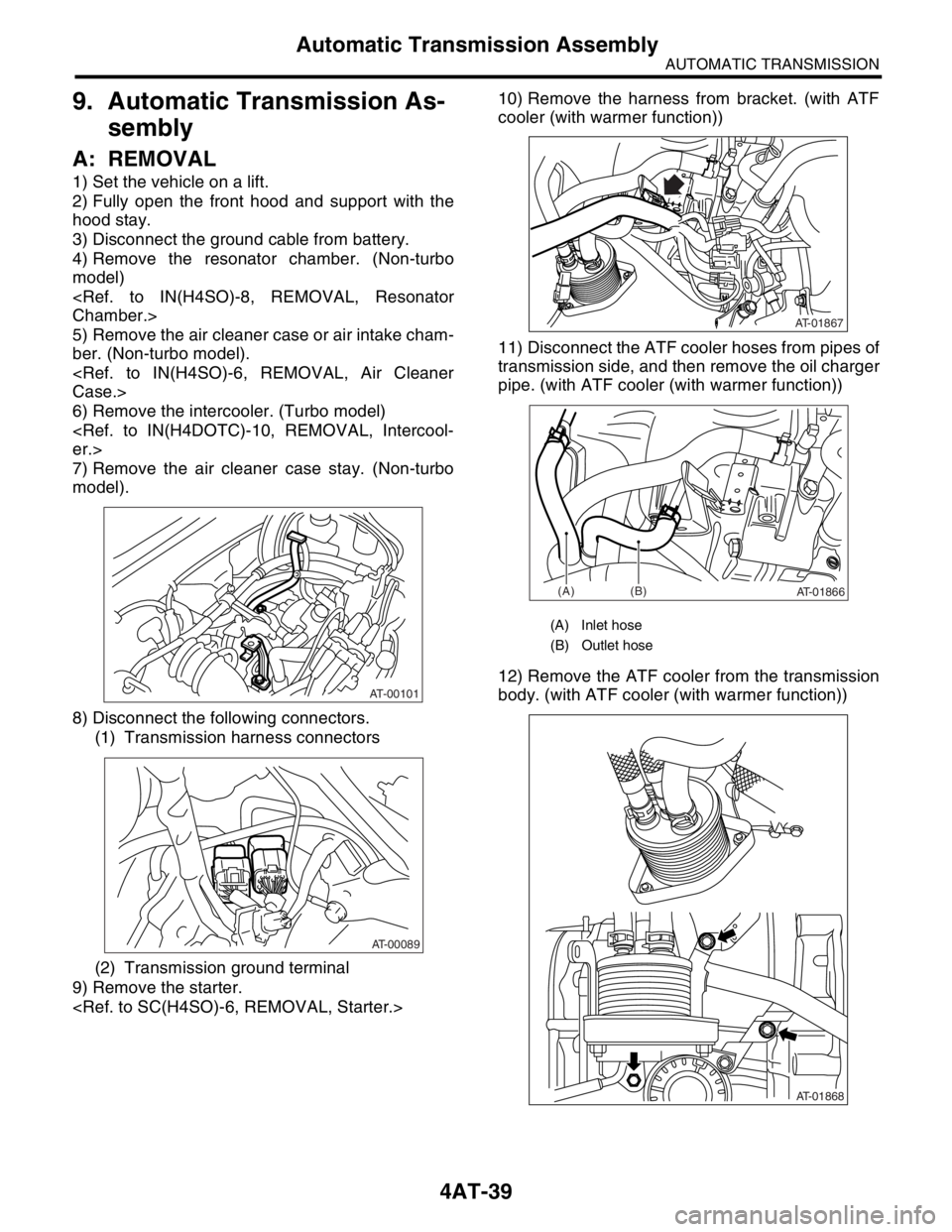
8) Disconnect the following connectors.
(1) Transmission harness connectors
(2) Transmission ground terminal
9) Remove the starter.
10) Remove the harness from bracket. (with ATF
cooler (with warmer function))
11) Disconnect the ATF cooler hoses from pipes of
transmission side, and then remove the oil charger
pipe. (with ATF cooler (with warmer function))
12) Remove the ATF cooler from the transmission
body. (with ATF cooler (with warmer function))
AT-00101
AT-00089
(A) Inlet hose
(B) Outlet hose
AT-01867
AT-01866(A)(B)
AT-01868
Page 2352 of 2870
4AT-40
AUTOMATIC TRANSMISSION
Automatic Transmission Assembly
13) Disconnect the hose from lower portion of ATF
cooler (with warmer function), and then secure the
ATF cooler to vehicle using string, etc.
14) Remove the pitching stopper.
15) Separate the torque converter clutch assembly
from drive plate.
(1) Remove the service hole plug.
(2) Remove the bolts which hold torque con-
verter clutch assembly to drive plate.
(3) Using ST, remove all bolts with slightly rotat-
ing crank sprocket.
CAUTION:
Be careful not to drop bolts into torque convert-
er clutch housing.16) Install the ST to torque converter clutch case.
ST 498277200 STOPPER SET
17) Remove the ATF level gauge.
CAUTION:
Plug the opening to prevent entering foreign
particles into transmission fluid.
18) Set ST.
ST 41099AC000 ENGINE SUPPORT ASSEM-
BLY
19) Remove the bolts which hold right upper side of
transmission to engine.
AT-02118
AT-00023
AT-00102
AT-00804
ST
AT-00680
AT-00105
ST
AT-00106
Page 2353 of 2870
4AT-41
AUTOMATIC TRANSMISSION
Automatic Transmission Assembly
20) Lift-up the vehicle.
21) Remove the under cover.
22) Remove the front, center, rear, exhaust pipes
and muffler. (Non-turbo model).
Pipe.>
Exhaust Pipe.>
AL, Muffler.>
23) Remove the center, rear exhaust pipe and muf-
fler. (Turbo model)
haust Pipe.>
AL, Rear Exhaust Pipe.>
16, REMOVAL, Muffler.>
24) Remove the heat shield cover. (If equipped)
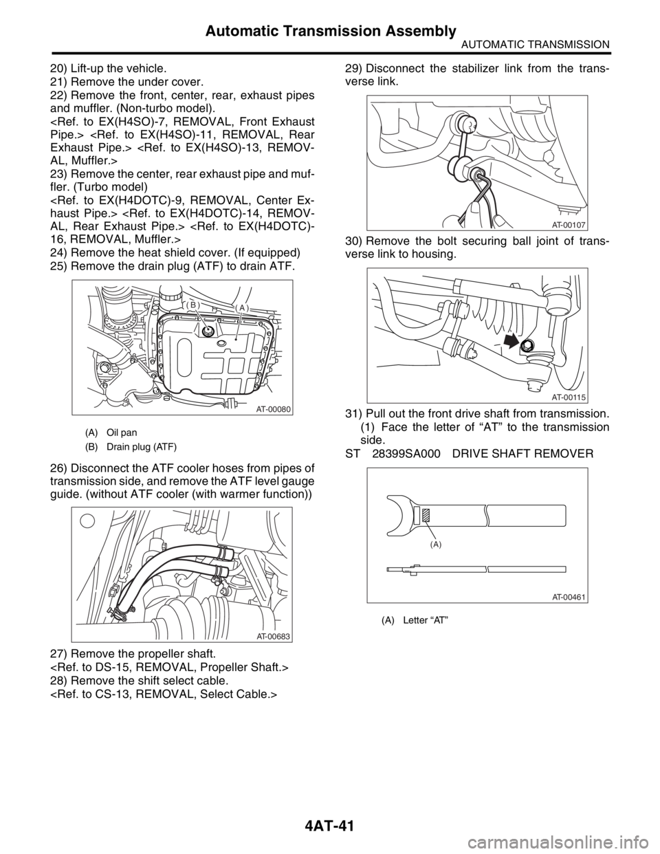
25) Remove the drain plug (ATF) to drain ATF.
26) Disconnect the ATF cooler hoses from pipes of
transmission side, and remove the ATF level gauge
guide. (without ATF cooler (with warmer function))
27) Remove the propeller shaft.
28) Remove the shift select cable.
29) Disconnect the stabilizer link from the trans-
verse link.
30) Remove the bolt securing ball joint of trans-
verse link to housing.
31) Pull out the front drive shaft from transmission.
(1) Face the letter of “AT” to the transmission
side.
ST 28399SA000 DRIVE SHAFT REMOVER
(A) Oil pan
(B) Drain plug (ATF)
AT-00080
(A)(B)
AT-00683
(A) Letter “AT”
AT-00107
AT-00115
AT-00461
(A)
Page 2354 of 2870
4AT-42
AUTOMATIC TRANSMISSION
Automatic Transmission Assembly
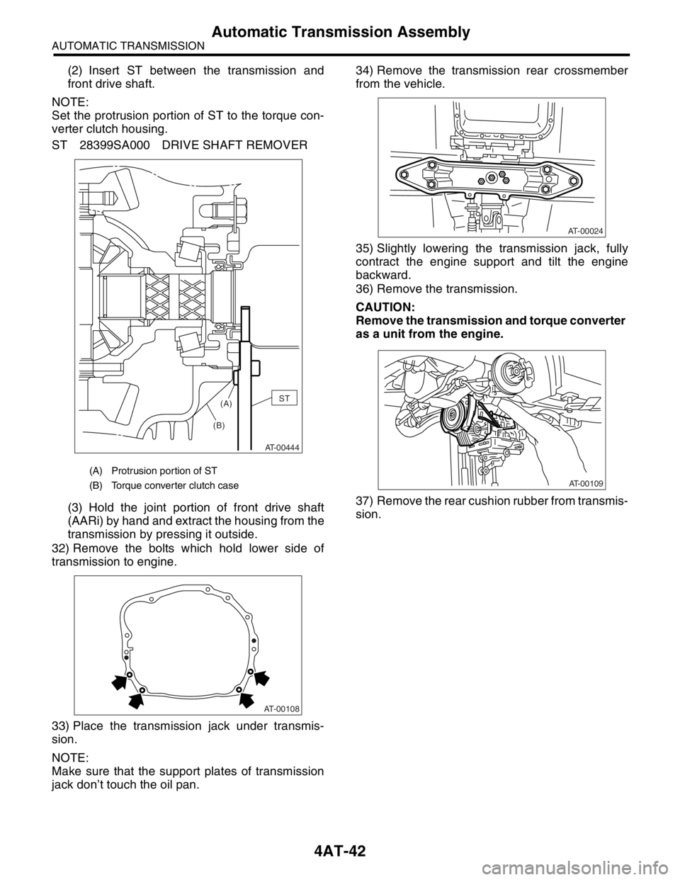
(2) Insert ST between the transmission and
front drive shaft.
NOTE:
Set the protrusion portion of ST to the torque con-
verter clutch housing.
ST 28399SA000 DRIVE SHAFT REMOVER
(3) Hold the joint portion of front drive shaft
(AARi) by hand and extract the housing from the
transmission by pressing it outside.
32) Remove the bolts which hold lower side of
transmission to engine.
33) Place the transmission jack under transmis-
sion.
NOTE:
Make sure that the support plates of transmission
jack don’t touch the oil pan.34) Remove the transmission rear crossmember
from the vehicle.
35) Slightly lowering the transmission jack, fully
contract the engine support and tilt the engine
backward.
36) Remove the transmission.
CAUTION:
Remove the transmission and torque converter
as a unit from the engine.
37) Remove the rear cushion rubber from transmis-
sion.
(A) Protrusion portion of ST
(B) Torque converter clutch case
AT-00444
ST
(A)
(B)
AT-00108
AT-00024
AT-00109
Page 2355 of 2870
4AT-43
AUTOMATIC TRANSMISSION
Automatic Transmission Assembly
B: INSTALLATION
1) Replace the differential side oil seal with a new
one.
tial Side Retainer Oil Seal.>
2) Install the rear cushion rubber to the transmis-
sion.
Tightening torque:
39 N
⋅m (4.0 kgf-m, 29 ft-lb)
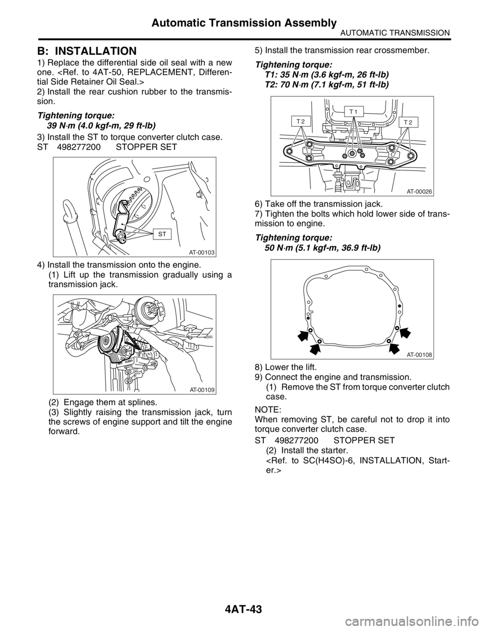
3) Install the ST to torque converter clutch case.
ST 498277200 STOPPER SET
4) Install the transmission onto the engine.
(1) Lift up the transmission gradually using a
transmission jack.
(2) Engage them at splines.
(3) Slightly raising the transmission jack, turn
the screws of engine support and tilt the engine
forward.5) Install the transmission rear crossmember.
Tightening torque:
T1: 35 N
⋅m (3.6 kgf-m, 26 ft-lb)
T2: 70 N
⋅m (7.1 kgf-m, 51 ft-lb)
6) Take off the transmission jack.
7) Tighten the bolts which hold lower side of trans-
mission to engine.
Tightening torque:
50 N
⋅m (5.1 kgf-m, 36.9 ft-lb)
8) Lower the lift.
9) Connect the engine and transmission.
(1) Remove the ST from torque converter clutch
case.
NOTE:
When removing ST, be careful not to drop it into
torque converter clutch case.
ST 498277200 STOPPER SET
(2) Install the starter.
er.>AT-00103
ST
AT-00109
AT-00026
T2T2
T1
AT-00108
Page 2356 of 2870
4AT-44
AUTOMATIC TRANSMISSION
Automatic Transmission Assembly
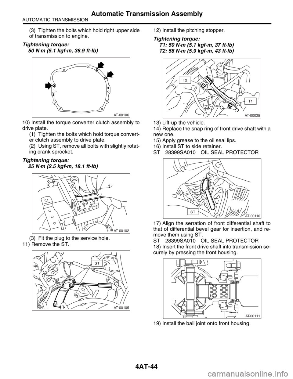
(3) Tighten the bolts which hold right upper side
of transmission to engine.
Tightening torque:
50 N
⋅m (5.1 kgf-m, 36.9 ft-lb)
10) Install the torque converter clutch assembly to
drive plate.
(1) Tighten the bolts which hold torque convert-
er clutch assembly to drive plate.
(2) Using ST, remove all bolts with slightly rotat-
ing crank sprocket.
Tightening torque:
25 N
⋅m (2.5 kgf-m, 18.1 ft-lb)
(3) Fit the plug to the service hole.
11) Remove the ST.12) Install the pitching stopper.
Tightening torque:
T1: 50 N
⋅m (5.1 kgf-m, 37 ft-lb)
T2: 58 N
⋅m (5.9 kgf-m, 43 ft-lb)
13) Lift-up the vehicle.
14) Replace the snap ring of front drive shaft with a
new one.
15) Apply grease to the oil seal lips.
16) Install ST to side retainer.
ST 28399SA010 OIL SEAL PROTECTOR
17) Align the serration of front differential shaft to
that of differential bevel gear for insertion, and re-
move them using ST.
ST 28399SA010 OIL SEAL PROTECTOR
18) Insert the front drive shaft into transmission se-
curely by pressing the front housing.
19) Install the ball joint onto front housing.
AT-00106
AT-00102
AT-00105
ST
AT-00025
T1
T2
AT-00110ST
AT-00111