2004 SUBARU FORESTER engine
[x] Cancel search: enginePage 1519 of 2870
ME(H4DOTC)-61
MECHANICAL
Timing Belt Assembly
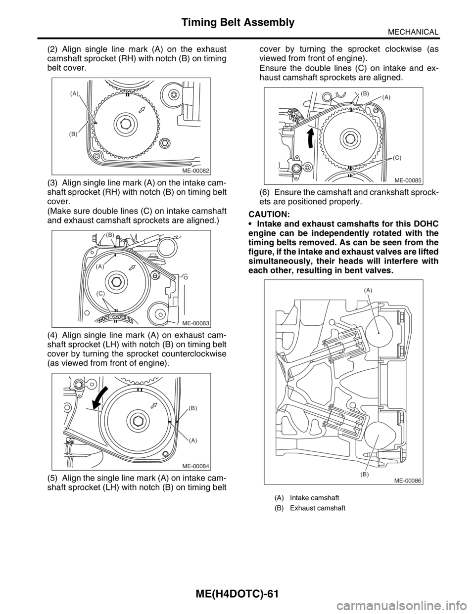
(2) Align single line mark (A) on the exhaust
camshaft sprocket (RH) with notch (B) on timing
belt cover.
(3) Align single line mark (A) on the intake cam-
shaft sprocket (RH) with notch (B) on timing belt
cover.
(Make sure double lines (C) on intake camshaft
and exhaust camshaft sprockets are aligned.)
(4) Align single line mark (A) on exhaust cam-
shaft sprocket (LH) with notch (B) on timing belt
cover by turning the sprocket counterclockwise
(as viewed from front of engine).
(5) Align the single line mark (A) on intake cam-
shaft sprocket (LH) with notch (B) on timing beltcover by turning the sprocket clockwise (as
viewed from front of engine).
Ensure the double lines (C) on intake and ex-
haust camshaft sprockets are aligned.
(6) Ensure the camshaft and crankshaft sprock-
ets are positioned properly.
CAUTION:
Intake and exhaust camshafts for this DOHC
engine can be independently rotated with the
timing belts removed. As can be seen from the
figure, if the intake and exhaust valves are lifted
simultaneously, their heads will interfere with
each other, resulting in bent valves.
ME-00082
(A)
(B)
ME-00083
(B)
(C)
(A)
ME-00084
(B)
(A)
(A) Intake camshaft
(B) Exhaust camshaft
ME-00085
(A) (B)
(C)
ME-00086
(A)
(B)
Page 1527 of 2870
ME(H4DOTC)-69
MECHANICAL
Camshaft
16) Remove the oil flow control solenoid valve as-
sembly, intake camshaft cap, and camshaft.
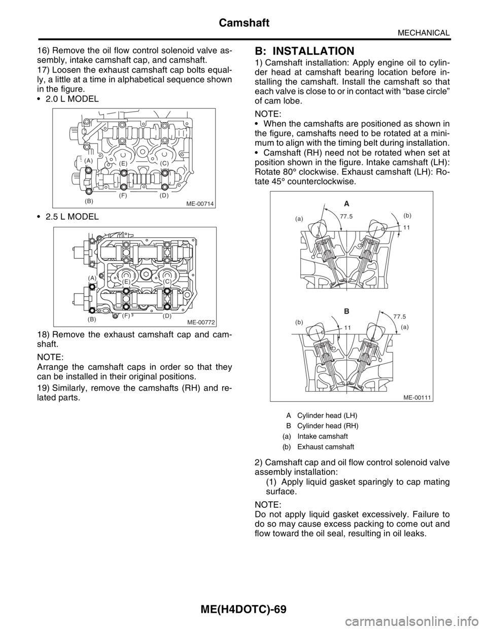
17) Loosen the exhaust camshaft cap bolts equal-
ly, a little at a time in alphabetical sequence shown
in the figure.
2.0 L MODEL
2.5 L MODEL
18) Remove the exhaust camshaft cap and cam-
shaft.
NOTE:
Arrange the camshaft caps in order so that they
can be installed in their original positions.
19) Similarly, remove the camshafts (RH) and re-
lated parts.B: INSTALLATION
1) Camshaft installation: Apply engine oil to cylin-
der head at camshaft bearing location before in-
stalling the camshaft. Install the camshaft so that
each valve is close to or in contact with “base circle”
of cam lobe.
NOTE:
When the camshafts are positioned as shown in
the figure, camshafts need to be rotated at a mini-
mum to align with the timing belt during installation.
Camshaft (RH) need not be rotated when set at
position shown in the figure. Intake camshaft (LH):
Rotate 80° clockwise. Exhaust camshaft (LH): Ro-
tate 45° counterclockwise.
2) Camshaft cap and oil flow control solenoid valve
assembly installation:
(1) Apply liquid gasket sparingly to cap mating
surface.
NOTE:
Do not apply liquid gasket excessively. Failure to
do so may cause excess packing to come out and
flow toward the oil seal, resulting in oil leaks.
ME-00714(B)
(A)
(E)
(F) (D)(C)
ME-00772
(A)(E)
(F)(B)(D)
(C)
A Cylinder head (LH)
B Cylinder head (RH)
(a) Intake camshaft
(b) Exhaust camshaft
ME-00111
1111
77.5 77.5
(a)
(b)
(a)(b)
A
B
Page 1528 of 2870
ME(H4DOTC)-70
MECHANICAL
Camshaft
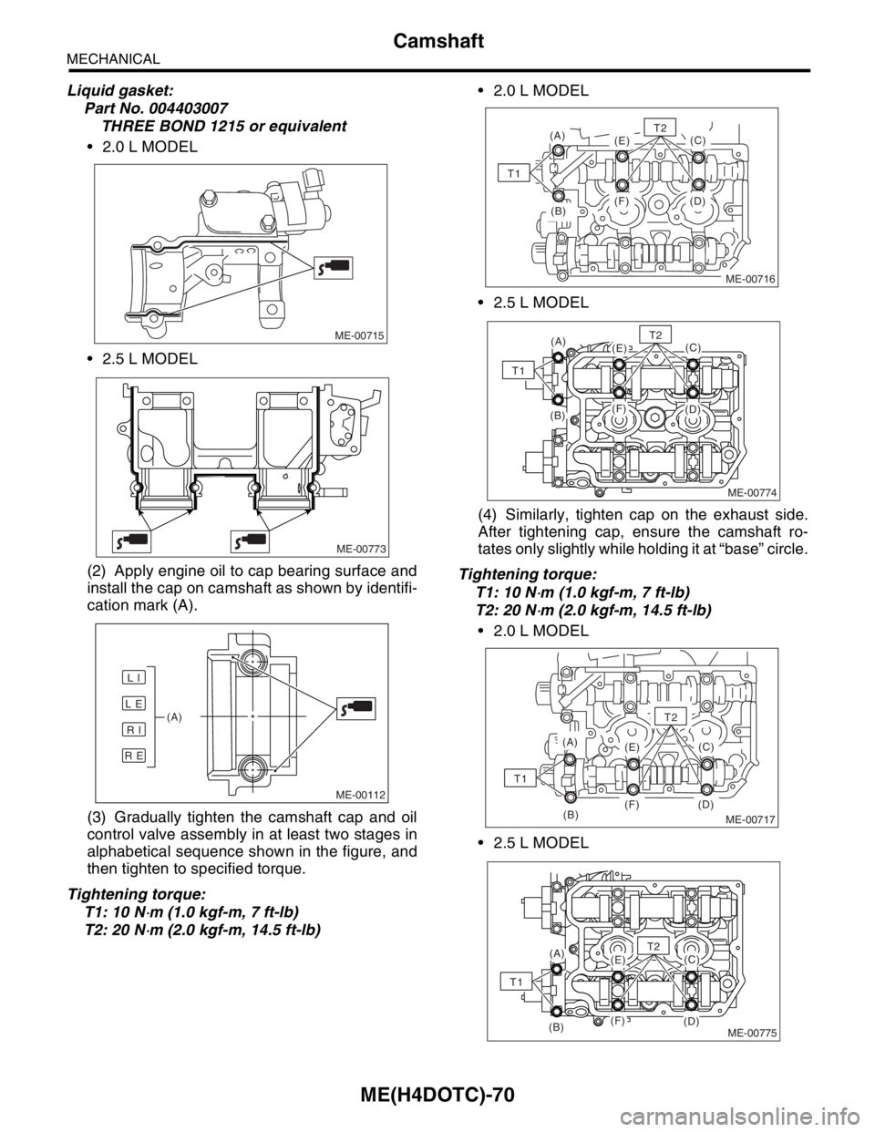
Liquid gasket:
Part No. 004403007
THREE BOND 1215 or equivalent
2.0 L MODEL
2.5 L MODEL
(2) Apply engine oil to cap bearing surface and
install the cap on camshaft as shown by identifi-
cation mark (A).
(3) Gradually tighten the camshaft cap and oil
control valve assembly in at least two stages in
alphabetical sequence shown in the figure, and
then tighten to specified torque.
Tightening torque:
T1: 10 N
⋅m (1.0 kgf-m, 7 ft-lb)
T2: 20 N
⋅m (2.0 kgf-m, 14.5 ft-lb) 2.0 L MODEL
2.5 L MODEL
(4) Similarly, tighten cap on the exhaust side.
After tightening cap, ensure the camshaft ro-
tates only slightly while holding it at “base” circle.
Tightening torque:
T1: 10 N
⋅m (1.0 kgf-m, 7 ft-lb)
T2: 20 N
⋅m (2.0 kgf-m, 14.5 ft-lb)
2.0 L MODEL
2.5 L MODEL
ME-00715
ME-00773
ME-00112
L E
R E
R I
L I
(A)
(B)
(A)
(E)
(F) (D)(C)
T1
ME-00716
T2
ME-00774
(A)(E)
(F)(B)(D)
(C)T2
T1
ME-00717(B)
(A)
(E)
(F) (D)(C)
T2
T1
ME-00775
(A)(E)
(F)(B)(D)
(C)T2
T1
Page 1533 of 2870
ME(H4DOTC)-75
MECHANICAL
Cylinder Head Assembly
19.Cylinder Head Assembly
A: REMOVAL
1) Remove the V-belt.
2) Remove the crank pulley.
3) Remove the timing belt cover.
4) Remove the timing belt assembly.
bly.>
5) Remove the cam sprocket.
6) Remove the intake manifold.
7) Remove the bolt which installs the A/C compres-
sor bracket on cylinder head.
8) Remove the camshaft.
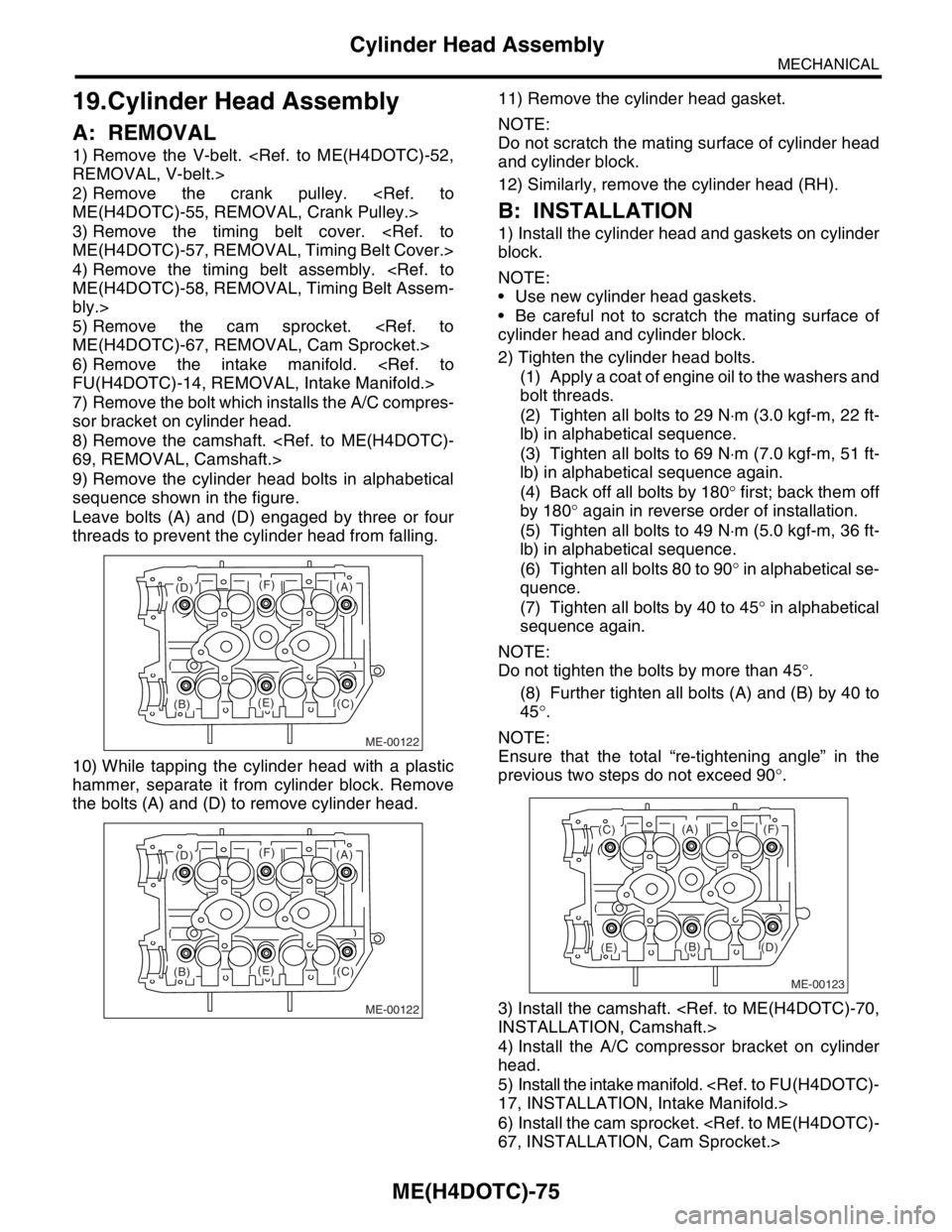
9) Remove the cylinder head bolts in alphabetical
sequence shown in the figure.
Leave bolts (A) and (D) engaged by three or four
threads to prevent the cylinder head from falling.
10) While tapping the cylinder head with a plastic
hammer, separate it from cylinder block. Remove
the bolts (A) and (D) to remove cylinder head.11) Remove the cylinder head gasket.
NOTE:
Do not scratch the mating surface of cylinder head
and cylinder block.
12) Similarly, remove the cylinder head (RH).
B: INSTALLATION
1) Install the cylinder head and gaskets on cylinder
block.
NOTE:
Use new cylinder head gaskets.
Be careful not to scratch the mating surface of
cylinder head and cylinder block.
2) Tighten the cylinder head bolts.
(1) Apply a coat of engine oil to the washers and
bolt threads.
(2) Tighten all bolts to 29 N⋅m (3.0 kgf-m, 22 ft-
lb) in alphabetical sequence.
(3) Tighten all bolts to 69 N⋅m (7.0 kgf-m, 51 ft-
lb) in alphabetical sequence again.
(4) Back off all bolts by 180° first; back them off
by 180° again in reverse order of installation.
(5) Tighten all bolts to 49 N⋅m (5.0 kgf-m, 36 ft-
lb) in alphabetical sequence.
(6) Tighten all bolts 80 to 90° in alphabetical se-
quence.
(7) Tighten all bolts by 40 to 45° in alphabetical
sequence again.
NOTE:
Do not tighten the bolts by more than 45°.
(8) Further tighten all bolts (A) and (B) by 40 to
45°.
NOTE:
Ensure that the total “re-tightening angle” in the
previous two steps do not exceed 90°.
3) Install the camshaft.
4) Install the A/C compressor bracket on cylinder
head.
5) Install the intake manifold.
6) Install the cam sprocket.
ME-00122
(B)(C)
(D)
(E)
(F)(A)
ME-00122
(B)(C)
(D)
(E)
(F)(A)
ME-00123
(B)
(C)
(D)(E)
(F)(A)
Page 1536 of 2870
ME(H4DOTC)-78
MECHANICAL
Cylinder Head Assembly
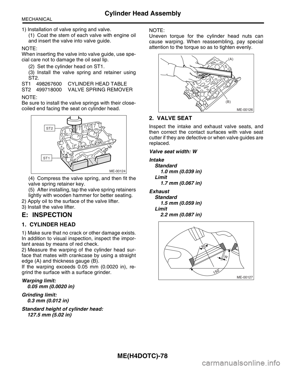
1) Installation of valve spring and valve.
(1) Coat the stem of each valve with engine oil
and insert the valve into valve guide.
NOTE:
When inserting the valve into valve guide, use spe-
cial care not to damage the oil seal lip.
(2) Set the cylinder head on ST1.
(3) Install the valve spring and retainer using
ST2.
ST1 498267600 CYLINDER HEAD TABLE
ST2 499718000 VALVE SPRING REMOVER
NOTE:
Be sure to install the valve springs with their close-
coiled end facing the seat on cylinder head.
(4) Compress the valve spring, and then fit the
valve spring retainer key.
(5) After installing, tap the valve spring retainers
lightly with wooden hammer for better seating.
2) Apply oil to the surface of the valve lifter.
3) Install the valve lifter.
E: INSPECTION
1. CYLINDER HEAD
1) Make sure that no crack or other damage exists.
In addition to visual inspection, inspect the impor-
tant areas by means of red check.
2) Measure the warping of the cylinder head sur-
face that mates with crankcase by using a straight
edge (A) and thickness gauge (B).
If the warping exceeds 0.05 mm (0.0020 in), re-
grind the surface with a surface grinder.
Warping limit:
0.05 mm (0.0020 in)
Grinding limit:
0.3 mm (0.012 in)
Standard height of cylinder head:
127.5 mm (5.02 in)NOTE:
Uneven torque for the cylinder head nuts can
cause warping. When reassembling, pay special
attention to the torque so as to tighten evenly.
2. VALVE SEAT
Inspect the intake and exhaust valve seats, and
then correct the contact surfaces with valve seat
cutter if they are defective or when valve guides are
replaced.
Valve seat width: W
Intake
Standard
1.0 mm (0.039 in)
Limit
1.7 mm (0.067 in)
Exhaust
Standard
1.5 mm (0.059 in)
Limit
2.2 mm (0.087 in)
ME-00124
ST1
ST2
ME-00126
(A)
(B)
ME-00127
W
Page 1537 of 2870
ME(H4DOTC)-79
MECHANICAL
Cylinder Head Assembly
3. VALVE GUIDE
1) Check the clearance between valve guide and
stem. The clearance can be checked by measuring
the outside diameter of valve stem and the inside
diameter of valve guide with outside and inside mi-
crometers respectively.
Clearance between the valve guide and valve
stem:
Standard
Intake
0.030 — 0.057 mm (0.0012 — 0.0022 in)
Exhaust
0.040 — 0.067 mm (0.0016 — 0.0026 in)
Limit
0.15 mm (0.0059 in)
2) If the clearance between valve guide and stem
exceeds the limit, replace the valve guide or valve
itself whichever shows greater amount of wear.
See the following procedure for valve guide re-
placement.
Valve guide inner diameter:
6.000 — 6.012 mm (0.2362 — 0.2367 in)
Valve stem outer diameters:
Intake
5.955 — 5.970 mm (0.2344 — 0.2350 in)
Exhaust
5.945 — 5.960 mm (0.2341 — 0.2346 in)
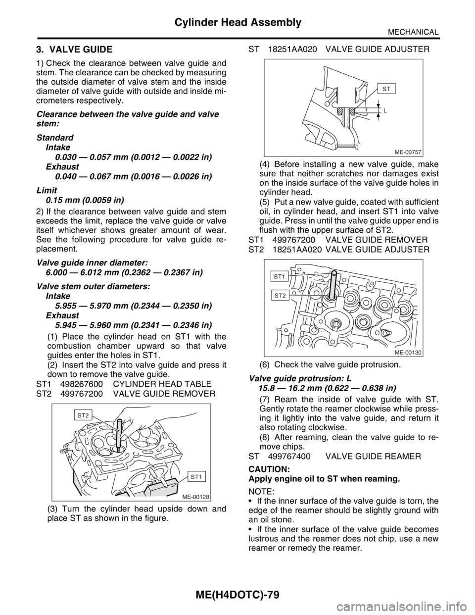
(1) Place the cylinder head on ST1 with the
combustion chamber upward so that valve
guides enter the holes in ST1.
(2) Insert the ST2 into valve guide and press it
down to remove the valve guide.
ST1 498267600 CYLINDER HEAD TABLE
ST2 499767200 VALVE GUIDE REMOVER
(3) Turn the cylinder head upside down and
place ST as shown in the figure.ST 18251AA020 VALVE GUIDE ADJUSTER
(4) Before installing a new valve guide, make
sure that neither scratches nor damages exist
on the inside surface of the valve guide holes in
cylinder head.
(5) Put a new valve guide, coated with sufficient
oil, in cylinder head, and insert ST1 into valve
guide. Press in until the valve guide upper end is
flush with the upper surface of ST2.
ST1 499767200 VALVE GUIDE REMOVER
ST2 18251AA020 VALVE GUIDE ADJUSTER
(6) Check the valve guide protrusion.
Valve guide protrusion: L
15.8 — 16.2 mm (0.622 — 0.638 in)
(7) Ream the inside of valve guide with ST.
Gently rotate the reamer clockwise while press-
ing it lightly into the valve guide, and return it
also rotating clockwise.
(8) After reaming, clean the valve guide to re-
move chips.
ST 499767400 VALVE GUIDE REAMER
CAUTION:
Apply engine oil to ST when reaming.
NOTE:
If the inner surface of the valve guide is torn, the
edge of the reamer should be slightly ground with
an oil stone.
If the inner surface of the valve guide becomes
lustrous and the reamer does not chip, use a new
reamer or remedy the reamer.
ME-00128
ST1
ST2ME-00757
ST
L
ME-00130
ST1
ST2
Page 1539 of 2870
ME(H4DOTC)-81
MECHANICAL
Cylinder Head Assembly
6. INTAKE AND EXHAUST VALVE OIL
SEAL
1) Replace the oil seal with a new one in the follow-
ing condition, Refer to procedure 2) for replace-
ment procedure.
Lip portion is damaged.
Spring is out of place.
Valve and valve seat are reconditioned.
Valve guide is replaced.
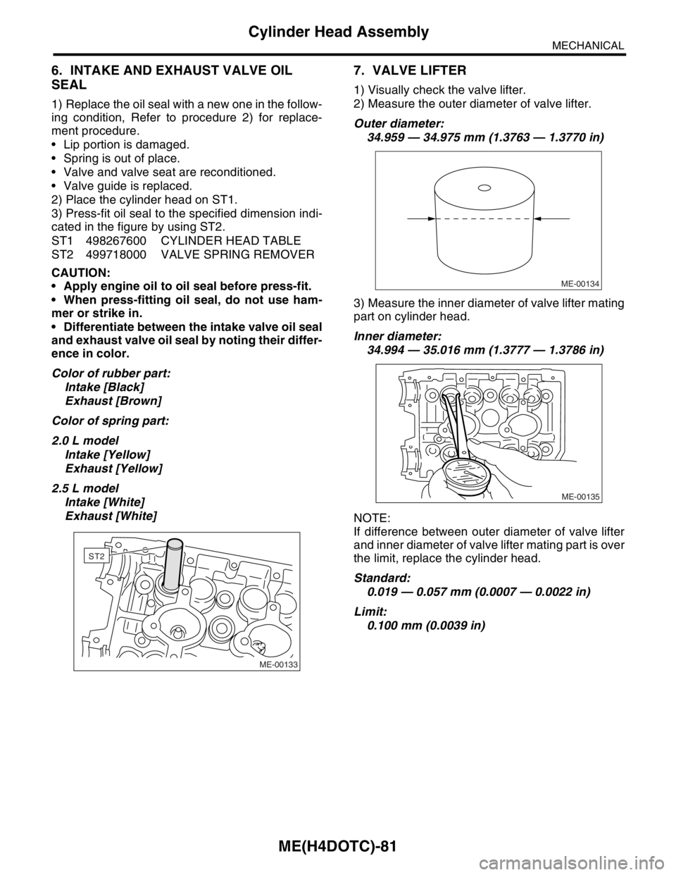
2) Place the cylinder head on ST1.
3) Press-fit oil seal to the specified dimension indi-
cated in the figure by using ST2.
ST1 498267600 CYLINDER HEAD TABLE
ST2 499718000 VALVE SPRING REMOVER
CAUTION:
Apply engine oil to oil seal before press-fit.
When press-fitting oil seal, do not use ham-
mer or strike in.
Differentiate between the intake valve oil seal
and exhaust valve oil seal by noting their differ-
ence in color.
Color of rubber part:
Intake [Black]
Exhaust [Brown]
Color of spring part:
2.0 L model
Intake [Yellow]
Exhaust [Yellow]
2.5 L model
Intake [White]
Exhaust [White]
7. VALVE LIFTER
1) Visually check the valve lifter.
2) Measure the outer diameter of valve lifter.
Outer diameter:
34.959 — 34.975 mm (1.3763 — 1.3770 in)
3) Measure the inner diameter of valve lifter mating
part on cylinder head.
Inner diameter:
34.994 — 35.016 mm (1.3777 — 1.3786 in)
NOTE:
If difference between outer diameter of valve lifter
and inner diameter of valve lifter mating part is over
the limit, replace the cylinder head.
Standard:
0.019 — 0.057 mm (0.0007 — 0.0022 in)
Limit:
0.100 mm (0.0039 in)
ME-00133
ST2
ME-00134
ME-00135
Page 1541 of 2870
FUJI HEAVY INDUSTRIES LTD. G8080GE3
2004 FORESTER SERVICE MANUAL QUICK REFERENCE INDEX
ENGINE SECTION 2
This service manual has been prepared
to provide SUBARU service personnel
with the necessary information and data
for the correct maintenance and repair
of SUBARU vehicles.
This manual includes the procedures
for maintenance, disassembling, reas-
sembling, inspection and adjustment of
components and diagnostics for guid-
ance of experienced mechanics.
Please peruse and utilize this manual
fully to ensure complete repair work for
satisfying our customers by keeping
their vehicle in optimum condition.
When replacement of parts during
repair work is needed, be sure to use
SUBARU genuine parts.
All information, illustration and specifi-
cations contained in this manual are
based on the latest product information
available at the time of publication
approval.FUEL INJECTION (FUEL SYSTEM) FU(H4DOTC)
EMISSION CONTROL
(AUX. EMISSION CONTROL DEVICE)EC(H4DOTC)
INTAKE (INDUCTION) IN(H4DOTC)
MECHANICAL ME(H4DOTC)
EXHAUST EX(H4DOTC)
COOLING CO(H4DOTC)
LUBRICATION LU(H4DOTC)
SPEED CONTROL SYSTEM SP(H4DOTC)
IGNITION IG(H4DOTC)
STARTING/CHARGING SYSTEM SC(H4DOTC)
ENGINE (DIAGNOSTIC) EN(H4DOTC)