Page 1504 of 2870
ME(H4DOTC)-46
MECHANICAL
Engine Assembly
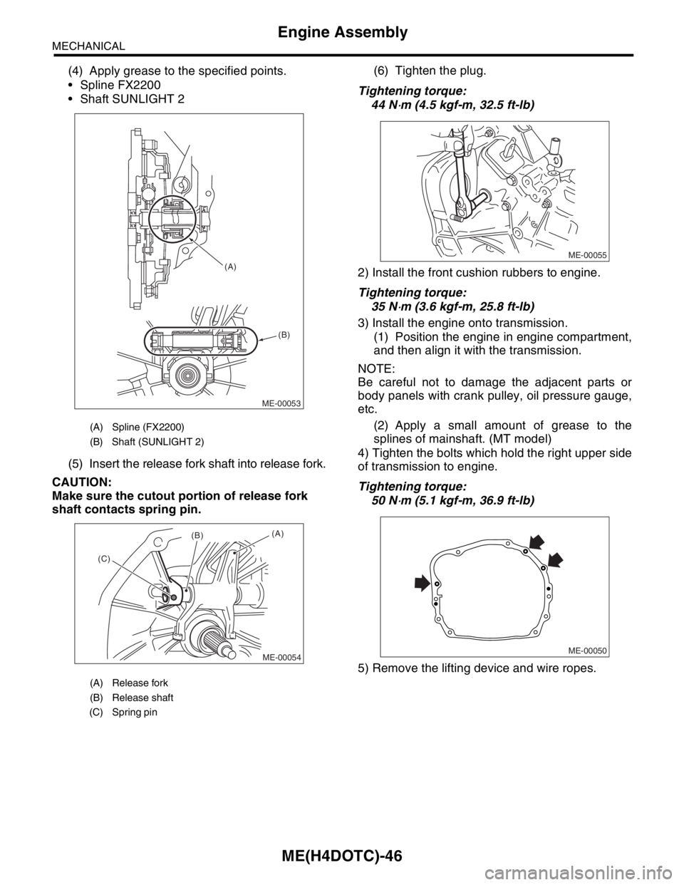
(4) Apply grease to the specified points.
Spline FX2200
Shaft SUNLIGHT 2
(5) Insert the release fork shaft into release fork.
CAUTION:
Make sure the cutout portion of release fork
shaft contacts spring pin.(6) Tighten the plug.
Tightening torque:
44 N
⋅m (4.5 kgf-m, 32.5 ft-lb)
2) Install the front cushion rubbers to engine.
Tightening torque:
35 N
⋅m (3.6 kgf-m, 25.8 ft-lb)
3) Install the engine onto transmission.
(1) Position the engine in engine compartment,
and then align it with the transmission.
NOTE:
Be careful not to damage the adjacent parts or
body panels with crank pulley, oil pressure gauge,
etc.
(2) Apply a small amount of grease to the
splines of mainshaft. (MT model)
4) Tighten the bolts which hold the right upper side
of transmission to engine.
Tightening torque:
50 N
⋅m (5.1 kgf-m, 36.9 ft-lb)
5) Remove the lifting device and wire ropes.
(A) Spline (FX2200)
(B) Shaft (SUNLIGHT 2)
(A) Release fork
(B) Release shaft
(C) Spring pin
ME-00053 (A)
(B)
ME-00054
(A)(B)
(C)ME-00055
ME-00050
Page 1505 of 2870
ME(H4DOTC)-47
MECHANICAL
Engine Assembly
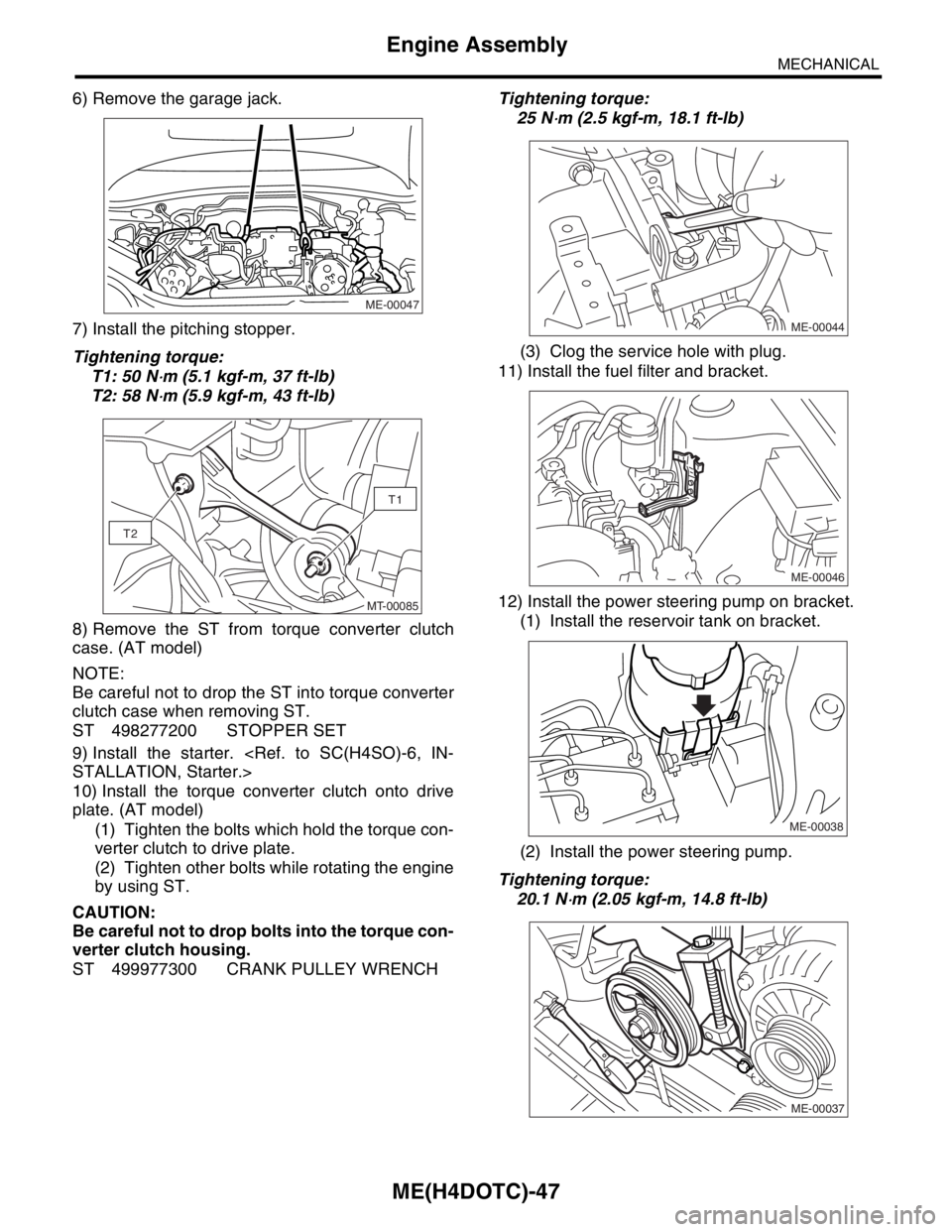
6) Remove the garage jack.
7) Install the pitching stopper.
Tightening torque:
T1: 50 N
⋅m (5.1 kgf-m, 37 ft-lb)
T2: 58 N
⋅m (5.9 kgf-m, 43 ft-lb)
8) Remove the ST from torque converter clutch
case. (AT model)
NOTE:
Be careful not to drop the ST into torque converter
clutch case when removing ST.
ST 498277200 STOPPER SET
9) Install the starter.
STALLATION, Starter.>
10) Install the torque converter clutch onto drive
plate. (AT model)
(1) Tighten the bolts which hold the torque con-
verter clutch to drive plate.
(2) Tighten other bolts while rotating the engine
by using ST.
CAUTION:
Be careful not to drop bolts into the torque con-
verter clutch housing.
ST 499977300 CRANK PULLEY WRENCHTightening torque:
25 N
⋅m (2.5 kgf-m, 18.1 ft-lb)
(3) Clog the service hole with plug.
11) Install the fuel filter and bracket.
12) Install the power steering pump on bracket.
(1) Install the reservoir tank on bracket.
(2) Install the power steering pump.
Tightening torque:
20.1 N
⋅m (2.05 kgf-m, 14.8 ft-lb)
ME-00047
T1
T2
MT-00085ME-00044
ME-00046
ME-00038
ME-00037
Page 1506 of 2870
ME(H4DOTC)-48
MECHANICAL
Engine Assembly
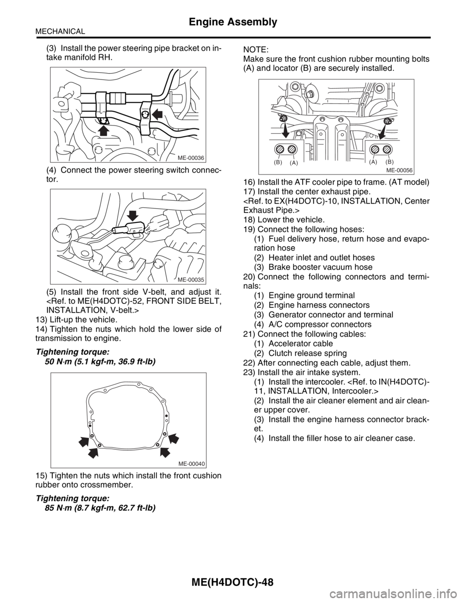
(3) Install the power steering pipe bracket on in-
take manifold RH.
(4) Connect the power steering switch connec-
tor.
(5) Install the front side V-belt, and adjust it.
INSTALLATION, V-belt.>
13) Lift-up the vehicle.
14) Tighten the nuts which hold the lower side of
transmission to engine.
Tightening torque:
50 N
⋅m (5.1 kgf-m, 36.9 ft-lb)
15) Tighten the nuts which install the front cushion
rubber onto crossmember.
Tightening torque:
85 N
⋅m (8.7 kgf-m, 62.7 ft-lb)NOTE:
Make sure the front cushion rubber mounting bolts
(A) and locator (B) are securely installed.
16) Install the ATF cooler pipe to frame. (AT model)
17) Install the center exhaust pipe.
Exhaust Pipe.>
18) Lower the vehicle.
19) Connect the following hoses:
(1) Fuel delivery hose, return hose and evapo-
ration hose
(2) Heater inlet and outlet hoses
(3) Brake booster vacuum hose
20) Connect the following connectors and termi-
nals:
(1) Engine ground terminal
(2) Engine harness connectors
(3) Generator connector and terminal
(4) A/C compressor connectors
21) Connect the following cables:
(1) Accelerator cable
(2) Clutch release spring
22) After connecting each cable, adjust them.
23) Install the air intake system.
(1) Install the intercooler.
11, INSTALLATION, Intercooler.>
(2) Install the air cleaner element and air clean-
er upper cover.
(3) Install the engine harness connector brack-
et.
(4) Install the filler hose to air cleaner case.
ME-00036
ME-00035
ME-00040
ME-00056
(A)
(A)(B)
(B)
Page 1507 of 2870
ME(H4DOTC)-49
MECHANICAL
Engine Assembly
24) Install the A/C pressure hoses.
NOTE:
Use new O-rings.
Tightening torque:
15 N
⋅m (1.5 kgf-m, 10.8 ft-lb)
25) Install the radiator.
STALLATION, Radiator.>
26) Install the coolant filler tank.
CO(H4SO)-42, INSTALLATION, Coolant Filler
Tank.>
27) Install the window washer tank.
28) Install the battery in the vehicle, and then con-
nect the cables.
29) Fill coolant.
COOLANT, REPLACEMENT, Engine Coolant.>
30) Charge the A/C system with refrigerant.
ing Procedure.>
31) Remove the front hood stay, and close the front
hood.
32) Take off the vehicle from lift arms.
ME-00026
Page 1508 of 2870
ME(H4DOTC)-50
MECHANICAL
Engine Mounting
10.Engine Mounting
A: REMOVAL
1) Remove the engine assembly.
ME(H4DOTC)-41, REMOVAL, Engine Assembly.>
2) Remove the engine mounting from engine as-
sembly.
B: INSTALLATION
Install in the reverse order of removal.
Tightening torque:
ENGINE MOUNTING;
35 N
⋅m (3.6 kgf-m, 25.8 ft-lb)
C: INSPECTION
Make sure there are no cracks or other damage.
Page 1509 of 2870
ME(H4DOTC)-51
MECHANICAL
Preparation for Overhaul
11.Preparation for Overhaul
A: PROCEDURE
1) After removing the engine from body, secure it in
the ST shown below.
ST1 498457000 ENGINE STAND ADAPTER
RH
ST2 498457100 ENGINE STAND ADAPTER
LH
ST3 499817000 ENGINE STAND
2) In this section the procedures described under
each index are all connected and stated in order. It
will be the complete procedure for overhauling of
the engine itself when you go through all steps in
the process.
Therefore, in this section, to conduct the particular
procedure within the flow of a section, you need to
go back and conduct the procedure described pre-
viously in order to do that particular procedure.
ME-00057ST3
ST2
ST1
Page 1513 of 2870
ME(H4DOTC)-55
MECHANICAL
Crank Pulley
13.Crank Pulley
A: REMOVAL
1) Remove the V-belt.
REMOVAL, V-belt.>
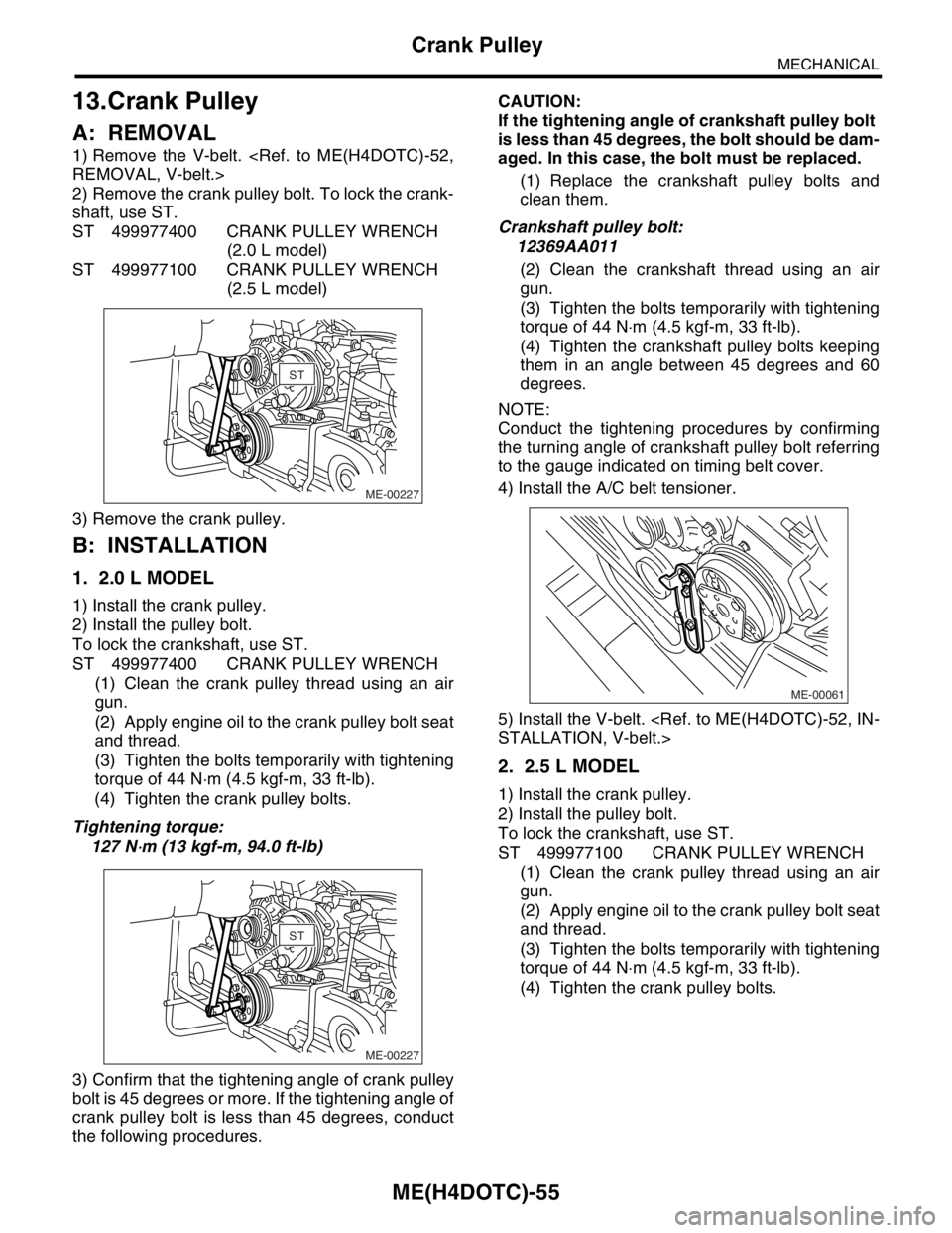
2) Remove the crank pulley bolt. To lock the crank-
shaft, use ST.
ST 499977400 CRANK PULLEY WRENCH
(2.0 L model)
ST 499977100 CRANK PULLEY WRENCH
(2.5 L model)
3) Remove the crank pulley.
B: INSTALLATION
1. 2.0 L MODEL
1) Install the crank pulley.
2) Install the pulley bolt.
To lock the crankshaft, use ST.
ST 499977400 CRANK PULLEY WRENCH
(1) Clean the crank pulley thread using an air
gun.
(2) Apply engine oil to the crank pulley bolt seat
and thread.
(3) Tighten the bolts temporarily with tightening
torque of 44 N⋅m (4.5 kgf-m, 33 ft-lb).
(4) Tighten the crank pulley bolts.
Tightening torque:
127 N
⋅m (13 kgf-m, 94.0 ft-lb)
3) Confirm that the tightening angle of crank pulley
bolt is 45 degrees or more. If the tightening angle of
crank pulley bolt is less than 45 degrees, conduct
the following procedures.CAUTION:
If the tightening angle of crankshaft pulley bolt
is less than 45 degrees, the bolt should be dam-
aged. In this case, the bolt must be replaced.
(1) Replace the crankshaft pulley bolts and
clean them.
Crankshaft pulley bolt:
12369AA011
(2) Clean the crankshaft thread using an air
gun.
(3) Tighten the bolts temporarily with tightening
torque of 44 N⋅m (4.5 kgf-m, 33 ft-lb).
(4) Tighten the crankshaft pulley bolts keeping
them in an angle between 45 degrees and 60
degrees.
NOTE:
Conduct the tightening procedures by confirming
the turning angle of crankshaft pulley bolt referring
to the gauge indicated on timing belt cover.
4) Install the A/C belt tensioner.
5) Install the V-belt.
STALLATION, V-belt.>
2. 2.5 L MODEL
1) Install the crank pulley.
2) Install the pulley bolt.
To lock the crankshaft, use ST.
ST 499977100 CRANK PULLEY WRENCH
(1) Clean the crank pulley thread using an air
gun.
(2) Apply engine oil to the crank pulley bolt seat
and thread.
(3) Tighten the bolts temporarily with tightening
torque of 44 N⋅m (4.5 kgf-m, 33 ft-lb).
(4) Tighten the crank pulley bolts.
ME-00227
STST
ME-00227
STST
ME-00061
Page 1514 of 2870
ME(H4DOTC)-56
MECHANICAL
Crank Pulley
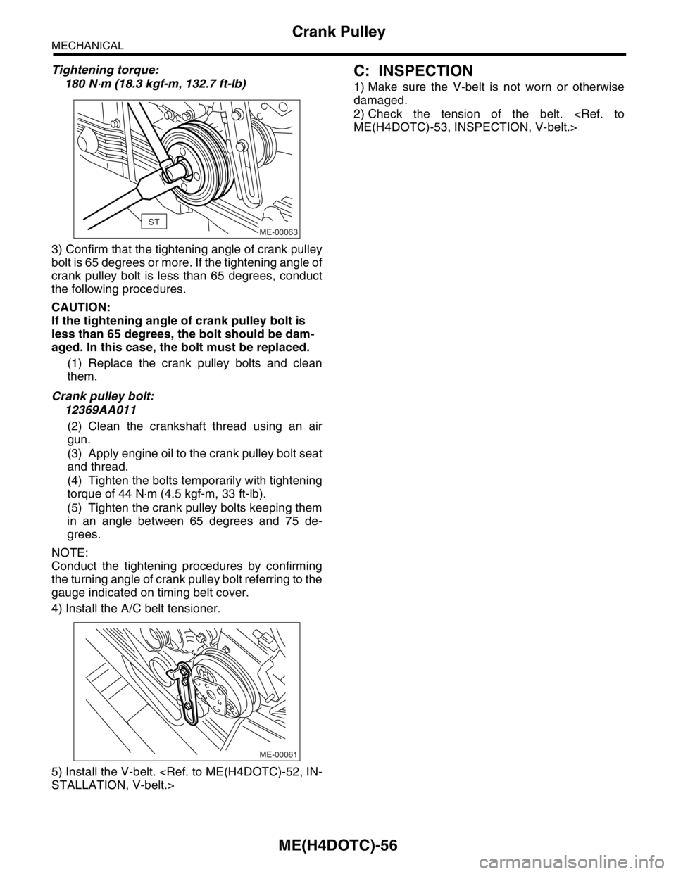
Tightening torque:
180 N
⋅m (18.3 kgf-m, 132.7 ft-lb)
3) Confirm that the tightening angle of crank pulley
bolt is 65 degrees or more. If the tightening angle of
crank pulley bolt is less than 65 degrees, conduct
the following procedures.
CAUTION:
If the tightening angle of crank pulley bolt is
less than 65 degrees, the bolt should be dam-
aged. In this case, the bolt must be replaced.
(1) Replace the crank pulley bolts and clean
them.
Crank pulley bolt:
12369AA011
(2) Clean the crankshaft thread using an air
gun.
(3) Apply engine oil to the crank pulley bolt seat
and thread.
(4) Tighten the bolts temporarily with tightening
torque of 44 N⋅m (4.5 kgf-m, 33 ft-lb).
(5) Tighten the crank pulley bolts keeping them
in an angle between 65 degrees and 75 de-
grees.
NOTE:
Conduct the tightening procedures by confirming
the turning angle of crank pulley bolt referring to the
gauge indicated on timing belt cover.
4) Install the A/C belt tensioner.
5) Install the V-belt.
STALLATION, V-belt.>
C: INSPECTION
1) Make sure the V-belt is not worn or otherwise
damaged.
2) Check the tension of the belt.
ME(H4DOTC)-53, INSPECTION, V-belt.>
ME-00063ST
ME-00061