2004 SUBARU FORESTER manual transmission
[x] Cancel search: manual transmissionPage 2592 of 2870

4AT(H4DOTC)-16
AUTOMATIC TRANSMISSION (DIAGNOSTIC)
Subaru Select Monitor
6) Using the scroll key, move the display screen up or down until desired data is shown.
A list of the support data is shown in the following table.
NOTE:
For detailed operation procedure, refer to the “SUBARU SELECT MONITOR OPERATION MANUAL”.
Contents Display Unit of measure
Battery voltage Battery Voltage V
Rear vehicle speed sensor signal Rear Wheel Speed km/h or MPH
Front vehicle speed sensor signal Front Wheel Speed km/h or MPH
Engine speed signal Engine Speed rpm
ATF temperature signal ATF Temp.°C or °F
Throttle position signal Throttle Sensor Voltage V
Gear position Gear Position —
Line pressure control duty ratio Line Pressure Duty Ratio %
Lock up clutch control duty ratio Lock Up Duty Ratio %
Transfer clutch control duty ratio Transfer Duty Ratio %
Power supply for throttle position sensor Throttle Sensor Power V
Torque converter turbine speed signal Turbine Revolution Speed rpm
2-4 brake timing pressure control duty ratio Brake Clutch Duty Ratio %
Low clutch duty ratio L/C Duty %
High clutch duty ratio H/C Duty %
Low & reverse brake duty ratio L&R/B Duty %
Throttle position Throttle position %
Accelerator pedal position Accel. Opening Angle %
Cruise control system Cruise Control Signal ON or OFF
Automatic transmission fluid temperature lamp ATF Temperature Lamp ON or OFF
Stop light switch signal Stop Light Switch ON or OFF
ABS signal ABS Signal ON or OFF
Parking range signal P Range Signal ON or OFF
Neutral range signal N Range Signal ON or OFF
Reverse range signal R Range Signal ON or OFF
Drive range signal D Range Signal ON or OFF
3rd range signal 3rd Range Signal ON or OFF
2nd range signal 2nd Range Signal ON or OFF
1st range signal 1st Range Signal ON or OFF
AT diagnosis indicator lamp Diagnosis Lamp ON or OFF
POWER switch signal POWER Switch ON or OFF
HOLD switch signal HOLD Switch ON or OFF
FWD switch signal FWD SW ON or OFF
Shift lock solenoid signal Shift Lock solenoid ON or OFF
Page 2593 of 2870
![SUBARU FORESTER 2004 Service Repair Manual 4AT(H4DOTC)-17
AUTOMATIC TRANSMISSION (DIAGNOSTIC)
Subaru Select Monitor
3. CLEAR MEMORY MODE
1) On the «Main Menu» display screen, select the
{2. Each System Check} and press the [YES] key.
2) On t SUBARU FORESTER 2004 Service Repair Manual 4AT(H4DOTC)-17
AUTOMATIC TRANSMISSION (DIAGNOSTIC)
Subaru Select Monitor
3. CLEAR MEMORY MODE
1) On the «Main Menu» display screen, select the
{2. Each System Check} and press the [YES] key.
2) On t](/manual-img/17/57426/w960_57426-2592.png)
4AT(H4DOTC)-17
AUTOMATIC TRANSMISSION (DIAGNOSTIC)
Subaru Select Monitor
3. CLEAR MEMORY MODE
1) On the «Main Menu» display screen, select the
{2. Each System Check} and press the [YES] key.
2) On the «System Selection Menu» display screen,
select the {Transmission Control System} and press
the [YES] key.
3) Press the [YES] key after the information of
transmission type is displayed.
4) On the «Transmission Diagnosis» display screen,
select the {Clear Memory} and press the [YES] key.
5) When the “Done” is shown on display screen,
turn the Subaru Select Monitor and ignition switch
to OFF.
NOTE:
For details concerning operation procedure, refer
to the SUBARU SELECT MONITOR OPERATION
MANUAL.
When {Clear Memory 2} is selected and executed,
DTC and learned control memory is cleared. If Clear
Memory 2 is performed, execute the learning con-
trol.
Select Monitor.>
4. FACILITATION OF LEARNING CON-
TROL
1) Shift the select lever to “P” range, and apply
parking brake.
2) Lift-up the vehicle.
3) Connect the Subaru Select Monitor to data link
connector, and then turn the ignition switch to ON.
4) Perform the {Clear Memory 2} using Subaru Select
Monitor.
5) Using Subaru Select Monitor, check that the DTC
is not output.
aru Select Monitor.>
6) Warm-up the engine until the ATF temperature
which is displayed on the Subaru Select Monitor is
within 60 — 90°C (140 — 194°F).
ERATION, Subaru Select Monitor.>
7) Shift the select lever to “R” range.
8) Turn all switches including headlight, air condi-
tioner, seat heater, rear defogger and etc. to OFF.
9) Turn the ignition switch to OFF.
10) Depress the brake pedal fully until the facilitation
of learning control is completed when the “Communi-
cation Failed!” is displayed on Subaru Select Monitor.
11) Turn the ignition switch to ON.
12) Check that the Subaru Select Monitor is re-
turned to normal operation.
13) Shift the select lever to “P” range, and then wait
for more than 3 seconds.14) Shift the select lever to “R” range, and then wait
for more than 3 seconds.
15) Shift the select lever to “N” range, and then wait
for more than 3 seconds.
16) Shift the select lever to “D” range, and then wait
for more than 3 seconds.
17) Shift the select lever to “N” range, and then wait
for more than 3 seconds.
18) Slightly depress the accelerator pedal fully.
19) Slightly release the accelerator pedal fully.
20) Start the engine, and idle it.
21) Shift the select lever to “D” range.
22) Start the facilitation of learning control. At this
time, the POWER indicator light in combination meter
blinks at 2 Hz. When the POWER indicator light does
not blink, turn the ignition switch to OFF and repeat
the procedures from step 4). When the POWER indi-
cator light which blinking at 2 Hz changes to blink at
0.5 Hz, facilitation of learning control is completed.
NOTE:
When blinking of POWER indicator light changes
from 2 Hz to 4 Hz during facilitation of learning con-
trol, repeat the procedure from step 4).
23) Shift the select lever to “N” range, and then turn
the ignition switch to OFF.
24) Shift the select lever to the “P” range, and then
complete the facilitation of learning control.
Page 2706 of 2870

4AT(H4DOTC)-130
AUTOMATIC TRANSMISSION (DIAGNOSTIC)
Symptom Related Diagnostic
Shock occurs when select lever is shifted from “D” to “1” range.TCM
Torque converter turbine speed sensor
Accelerator pedal position sensor
ATF temperature sensor
Line pressure linear solenoid
Control valve
ATF deterioration
Low & reverse brake duty solenoid
Low & reverse clutch solenoid
Shock occurs when select lever is shifted from “2” to “1” range.TCM
Torque converter turbine speed sensor
Accelerator pedal position sensor
ATF temperature sensor
Line pressure linear solenoid
Control valve
Low & reverse clutch
ATF deterioration
2-4 brake duty solenoid
Low & reverse brake duty solenoid
Shock occurs when accelerator pedal is released at medium
speeds.TCM
Accelerator pedal position sensor
ATF temperature sensor
Line pressure linear solenoid
Control valve
Lock-up damper
Engine performance
Vibration occurs during straight-forward operation.TCM
Lock-up duty solenoid
Lock-up facing
Lock-up damper
HOLD switch
Vibration occurs during turns (tight corner “braking” phenome-
non).TCM
Front vehicle speed sensor
Rear vehicle speed sensor
Accelerator pedal position sensor
ATF temperature sensor
Transfer clutch
Transfer valve
Transfer duty solenoid
ATF deterioration
Harness
HOLD switch
Front wheel slippage occurs during standing starts.TCM
Front vehicle speed sensor
Accelerator pedal position sensor
ATF temperature sensor
Control valve
Transfer clutch
Transfer valve
Transfer pipe
Transfer duty solenoid
Vehicle is not set in FWD mode.TCM
Transfer clutch
Transfer valve
Transfer duty solenoid
Select lever is hard to move. Select cable
Select lever
Detente spring
Manual plate Symptom Problem parts
Page 2707 of 2870

4AT(H4DOTC)-131
AUTOMATIC TRANSMISSION (DIAGNOSTIC)
Symptom Related Diagnostic
Select lever is too high to move (unreasonable resistance). Detente spring
Manual plate
Select lever slips out of operation during acceleration or while
driving on rough terrain. Select cable
Select lever
Detente spring
Manual plate Symptom Problem parts
Page 2709 of 2870

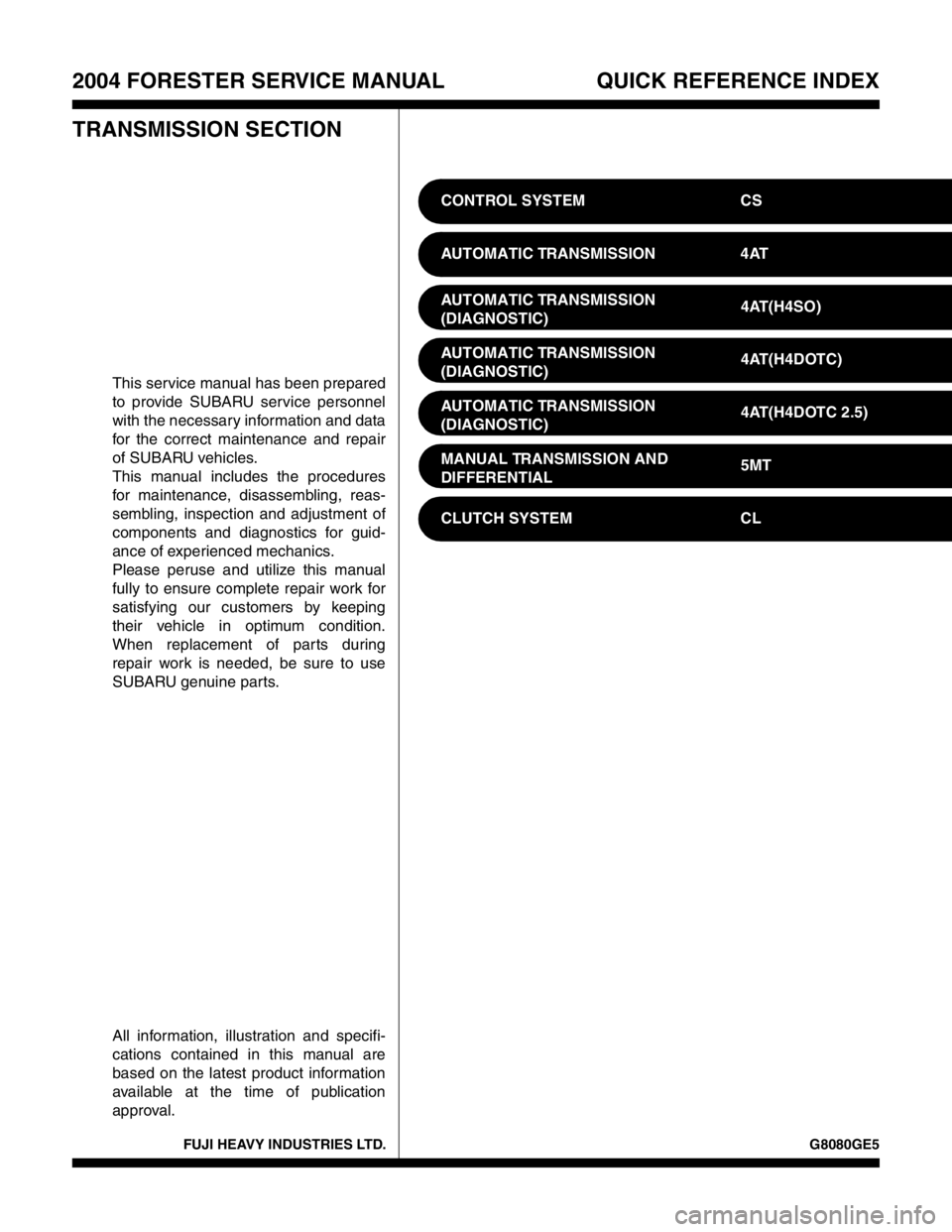
FUJI HEAVY INDUSTRIES LTD. G8080GE5
2004 FORESTER SERVICE MANUAL QUICK REFERENCE INDEX
TRANSMISSION SECTION
This service manual has been prepared
to provide SUBARU service personnel
with the necessary information and data
for the correct maintenance and repair
of SUBARU vehicles.
This manual includes the procedures
for maintenance, disassembling, reas-
sembling, inspection and adjustment of
components and diagnostics for guid-
ance of experienced mechanics.
Please peruse and utilize this manual
fully to ensure complete repair work for
satisfying our customers by keeping
their vehicle in optimum condition.
When replacement of parts during
repair work is needed, be sure to use
SUBARU genuine parts.
All information, illustration and specifi-
cations contained in this manual are
based on the latest product information
available at the time of publication
approval.CONTROL SYSTEM CS
AUTOMATIC TRANSMISSION 4AT
AUTOMATIC TRANSMISSION
(DIAGNOSTIC)4AT(H4SO)
AUTOMATIC TRANSMISSION
(DIAGNOSTIC)4AT(H4DOTC)
AUTOMATIC TRANSMISSION
(DIAGNOSTIC)4AT(H4DOTC 2.5)
MANUAL TRANSMISSION AND
DIFFERENTIAL5MT
CLUTCH SYSTEM CL
Page 2712 of 2870

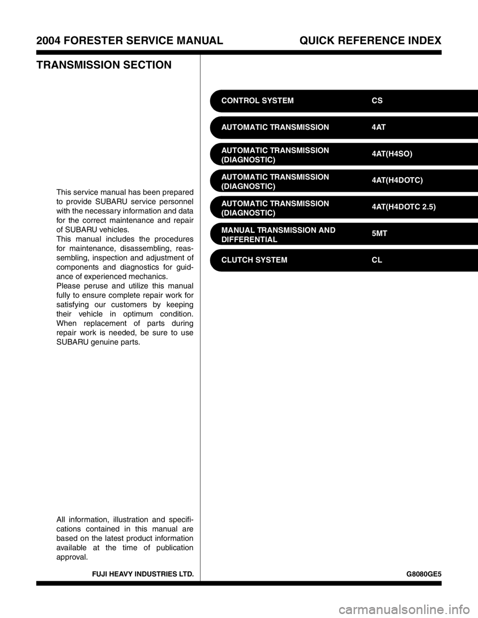
FUJI HEAVY INDUSTRIES LTD. G8080GE5
2004 FORESTER SERVICE MANUAL QUICK REFERENCE INDEX
TRANSMISSION SECTION
This service manual has been prepared
to provide SUBARU service personnel
with the necessary information and data
for the correct maintenance and repair
of SUBARU vehicles.
This manual includes the procedures
for maintenance, disassembling, reas-
sembling, inspection and adjustment of
components and diagnostics for guid-
ance of experienced mechanics.
Please peruse and utilize this manual
fully to ensure complete repair work for
satisfying our customers by keeping
their vehicle in optimum condition.
When replacement of parts during
repair work is needed, be sure to use
SUBARU genuine parts.
All information, illustration and specifi-
cations contained in this manual are
based on the latest product information
available at the time of publication
approval.CONTROL SYSTEM CS
AUTOMATIC TRANSMISSION 4AT
AUTOMATIC TRANSMISSION
(DIAGNOSTIC)4AT(H4SO)
AUTOMATIC TRANSMISSION
(DIAGNOSTIC)4AT(H4DOTC)
AUTOMATIC TRANSMISSION
(DIAGNOSTIC)4AT(H4DOTC 2.5)
MANUAL TRANSMISSION AND
DIFFERENTIAL5MT
CLUTCH SYSTEM CL
Page 2713 of 2870

MANUAL TRANSMISSION AND
DIFFERENTIAL
5MT
Page
1. General Description ....................................................................................2
2. Transmission Gear Oil ..............................................................................31
3. Manual Transmission Assembly ...............................................................32
4. Transmission Mounting System ................................................................39
5. Oil Seal......................................................................................................41
6. Differential Side Retainer Oil Seal.............................................................42
7. Switches and Harness ..............................................................................43
8. Vehicle Speed Sensor...............................................................................46
9. Preparation for Overhaul ...........................................................................47
10. Oil Pump ...................................................................................................48
11. Transfer Case and Extension Case Assembly..........................................50
12. Transfer Drive Gear ..................................................................................54
13. Transfer Driven Gear ................................................................................56
14. Center Differential .....................................................................................58
15. Reverse Check Sleeve..............................................................................59
16. Transmission Case ...................................................................................62
17. Main Shaft Assembly For Single-Range ...................................................69
18. Main Shaft Assembly For Dual-Range ......................................................77
19. Input Shaft Assembly ................................................................................83
20. Drive Pinion Shaft Assembly .....................................................................87
21. Front Differential Assembly .......................................................................96
22. Speedometer Gear..................................................................................103
23. Reverse Idler Gear ..................................................................................104
24. Shifter Fork and Rod ...............................................................................106
25. Counter Gear ..........................................................................................109
26. General Diagnostic..................................................................................111
Page 2714 of 2870

5MT-2
MANUAL TRANSMISSION AND DIFFERENTIAL
General Description
1. General Description
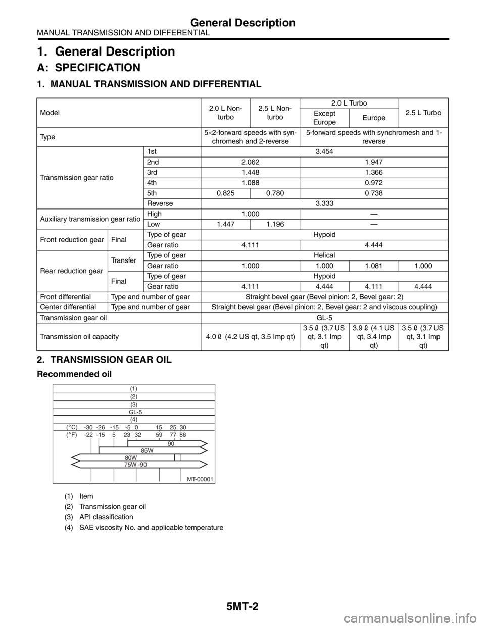
A: SPECIFICATION
1. MANUAL TRANSMISSION AND DIFFERENTIAL
2. TRANSMISSION GEAR OIL
Recommended oil
Model2.0 L Non-
turbo2.5 L Non-
turbo2.0 L Turbo
2.5 L Turbo
Except
EuropeEurope
Ty p e5×2-forward speeds with syn-
chromesh and 2-reverse5-forward speeds with synchromesh and 1-
reverse
Transmission gear ratio1st 3.454
2nd 2.062 1.947
3rd 1.448 1.366
4th 1.088 0.972
5th 0.825 0.780 0.738
Reverse 3.333
Auxiliary transmission gear ratioHigh 1.000 —
Low 1.447 1.196 —
Front reduction gear FinalType of gear Hypoid
Gear ratio 4.111 4.444
Rear reduction gearTransferType of gear Helical
Gear ratio 1.000 1.000 1.081 1.000
FinalType of gear Hypoid
Gear ratio 4.111 4.444 4.111 4.444
Front differential Type and number of gear Straight bevel gear (Bevel pinion: 2, Bevel gear: 2)
Center differential Type and number of gear Straight bevel gear (Bevel pinion: 2, Bevel gear: 2 and viscous coupling)
Transmission gear oil GL-5
Transmission oil capacity 4.02 (4.2 US qt, 3.5 Imp qt)3.52 (3.7 US
qt, 3.1 Imp
qt)3.92 (4.1 US
qt, 3.4 Imp
qt)3.52 (3.7 US
qt, 3.1 Imp
qt)
(1) Item
(2) Transmission gear oil
(3) API classification
(4) SAE viscosity No. and applicable temperature
MT-00001
(1)
(4) GL-5(3) (2)
( C)( F)-30 -26 -15 15
90
85W
80W
75W -9025 30 -5 0-22-1523328659775