Page 1980 of 2870
FU(H4DOTC 2.5)-50
FUEL INJECTION (FUEL SYSTEM)
Fuel Filler Pipe
6) Insert the fuel filler hose (A) approx. 35 to 40 mm
(1.38 to 1.57 in) over the lower end of fuel filler pipe
and tighten the clamp.
CAUTION:
Do not allow clips to touch the air vent hose (B)
and rear suspension crossmember.
7) Insert the air vent hose approx. 25 to 30 mm
(0.98 to 1.18 in) into the lower end of air vent pipe
and hold clip.
L = 27.5
±2.5 mm (1.083±0.098 in)
8) Tighten the bolt which holds fuel filler pipe brack-
et on body.
Tightening torque:
7.5 N·m (0.75 kgf-m, 5.4 ft-lb)9) Hold the evaporation hoses onto clip of fuel filler
pipe.
10) Install the fuel filler pipe protector.
11) Install the rear right wheel.
12) Lower the vehicle.
13) Tighten the wheel nuts.
14) Connect the connector to fuel pump relay.
(1) Hose
(2) Clip
(3) Pipe
(A)
(B)
FU-00101
FU-00104
(1)(2)
L/2
L(3)
FU-00100
FU-00098
FU-00097
FU-00096
FU-00262
Page 2308 of 2870

CS-23
CONTROL SYSTEM
MT Drive Select Lever
6. MT Drive Select Lever
A: REMOVAL
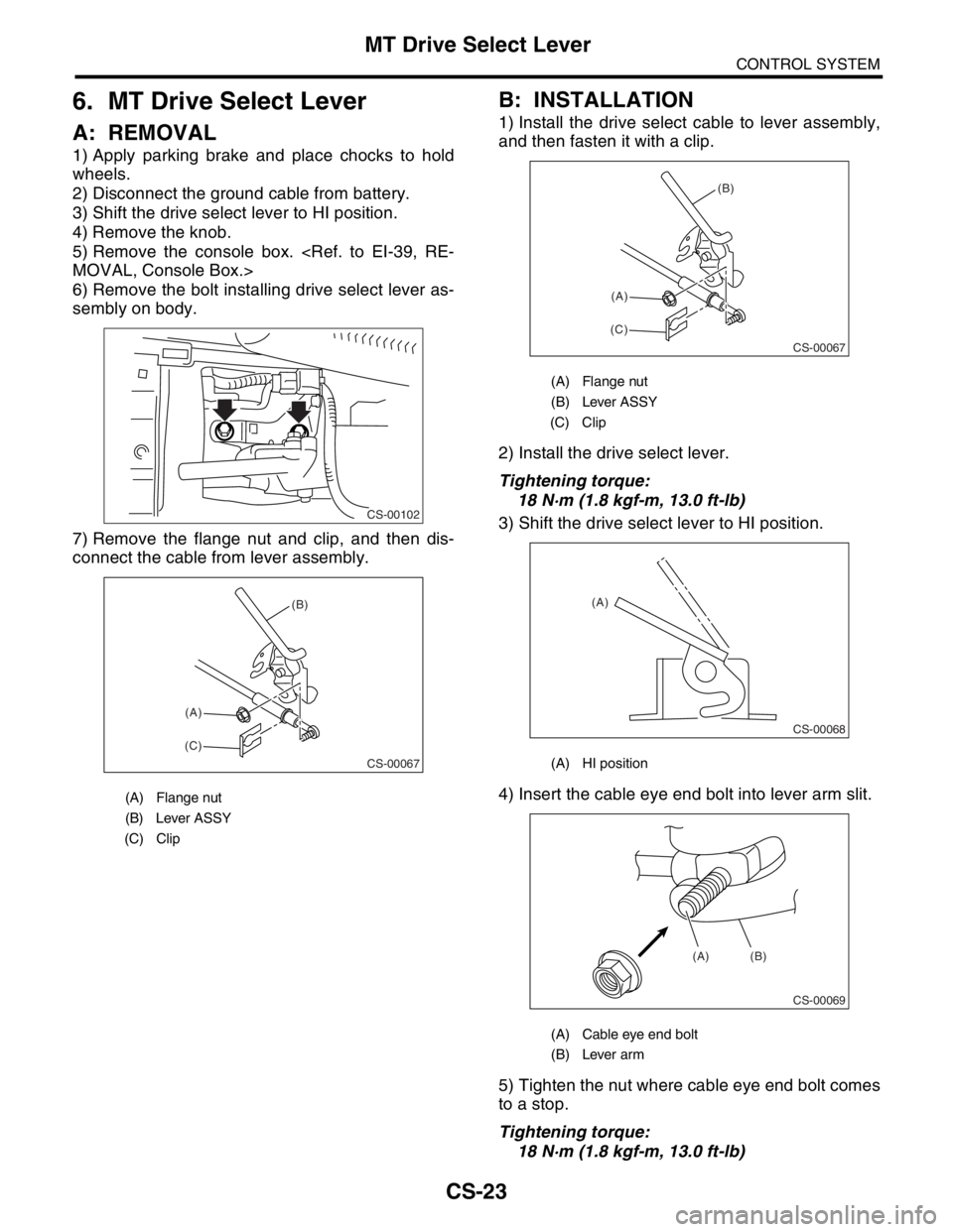
1) Apply parking brake and place chocks to hold
wheels.
2) Disconnect the ground cable from battery.
3) Shift the drive select lever to HI position.
4) Remove the knob.
5) Remove the console box.
MOVAL, Console Box.>
6) Remove the bolt installing drive select lever as-
sembly on body.
7) Remove the flange nut and clip, and then dis-
connect the cable from lever assembly.
B: INSTALLATION
1) Install the drive select cable to lever assembly,
and then fasten it with a clip.
2) Install the drive select lever.
Tightening torque:
18 N·m (1.8 kgf-m, 13.0 ft-lb)
3) Shift the drive select lever to HI position.
4) Insert the cable eye end bolt into lever arm slit.
5) Tighten the nut where cable eye end bolt comes
to a stop.
Tightening torque:
18 N·m (1.8 kgf-m, 13.0 ft-lb)
(A) Flange nut
(B) Lever ASSY
(C) Clip
CS-00102
CS-00067
(C)(A)(B)
(A) Flange nut
(B) Lever ASSY
(C) Clip
(A) HI position
(A) Cable eye end bolt
(B) Lever arm
CS-00067
(C)(A)(B)
CS-00068
(A)
CS-00069
(A) (B)
Page 2842 of 2870

CL-16
CLUTCH SYSTEM
Clutch Disc and Cover
2. Clutch Disc and Cover
A: REMOVAL
1) Remove the transmission assembly from vehicle
body.
mission Assembly.>
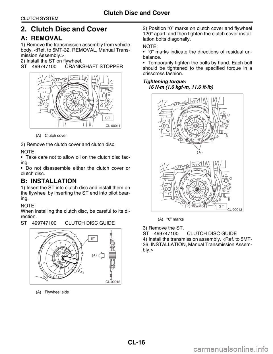
2) Install the ST on flywheel.
ST 499747100 CRANKSHAFT STOPPER
3) Remove the clutch cover and clutch disc.
NOTE:
Take care not to allow oil on the clutch disc fac-
ing.
Do not disassemble either the clutch cover or
clutch disc.
B: INSTALLATION
1) Insert the ST into clutch disc and install them on
the flywheel by inserting the ST end into pilot bear-
ing.
NOTE:
When installing the clutch disc, be careful to its di-
rection.
ST 499747100 CLUTCH DISC GUIDE2) Position “0” marks on clutch cover and flywheel
120° apart, and then tighten the clutch cover instal-
lation bolts diagonally.
NOTE:
“0” marks indicate the directions of residual un-
balance.
Temporarily tighten the bolts by hand. Each bolt
should be tightened to the specified torque in a
crisscross fashion.
Tightening torque:
16 N
⋅m (1.6 kgf-m, 11.6 ft-lb)
3) Remove the ST.
ST 499747100 CLUTCH DISC GUIDE
4) Install the transmission assembly.
36, INSTALLATION, Manual Transmission Assem-
bly.>
(A) Clutch cover
(A) Flywheel side
CL-00011
(A)
ST
CL-00012
(A)
ST
(A) “0” marks
CL-00013 (A)ST(2)
(5)
(3)(1)
(6)
(4)
Page 2845 of 2870

CL-19
CLUTCH SYSTEM
Flywheel
3. Flywheel
A: REMOVAL
1) Remove the transmission assembly.
5MT-32, REMOVAL, Manual Transmission As-
sembly.>
2) Remove the clutch cover and clutch disc.
to CL-16, REMOVAL, Clutch Disc and Cover.>
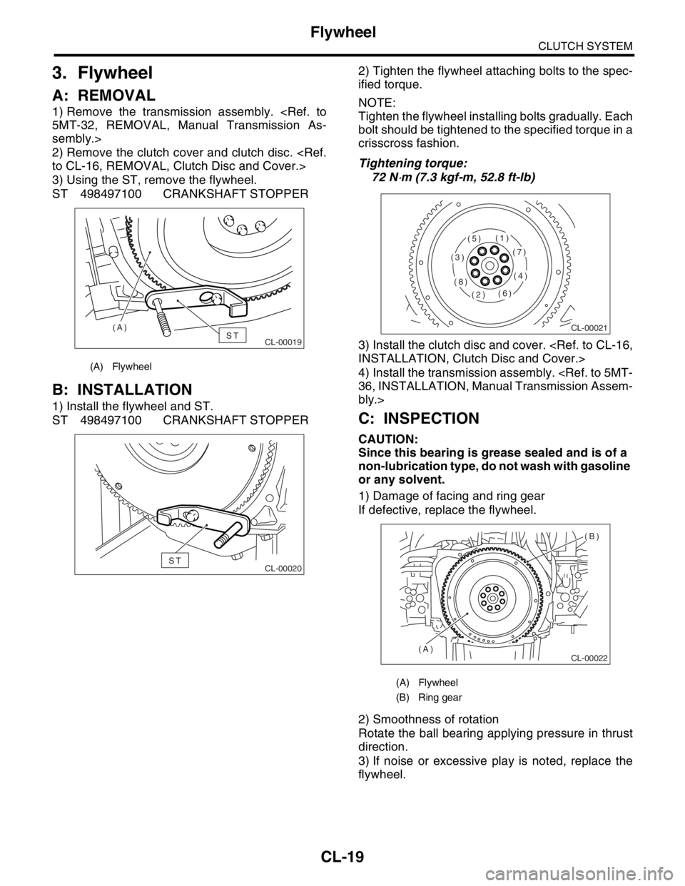
3) Using the ST, remove the flywheel.
ST 498497100 CRANKSHAFT STOPPER
B: INSTALLATION
1) Install the flywheel and ST.
ST 498497100 CRANKSHAFT STOPPER2) Tighten the flywheel attaching bolts to the spec-
ified torque.
NOTE:
Tighten the flywheel installing bolts gradually. Each
bolt should be tightened to the specified torque in a
crisscross fashion.
Tightening torque:
72 N
⋅m (7.3 kgf-m, 52.8 ft-lb)
3) Install the clutch disc and cover.
INSTALLATION, Clutch Disc and Cover.>
4) Install the transmission assembly.
36, INSTALLATION, Manual Transmission Assem-
bly.>
C: INSPECTION
CAUTION:
Since this bearing is grease sealed and is of a
non-lubrication type, do not wash with gasoline
or any solvent.
1) Damage of facing and ring gear
If defective, replace the flywheel.
2) Smoothness of rotation
Rotate the ball bearing applying pressure in thrust
direction.
3) If noise or excessive play is noted, replace the
flywheel.
(A) Flywheel
CL-00019ST (A)
CL-00020ST
(A) Flywheel
(B) Ring gear
CL-00021
(1)
(2)
(3)
(4)
(5)
(6)
(7)
(8)
CL-00022
(B)
(A)
Page:
< prev 1-8 9-16 17-24