2004 SUBARU FORESTER check engine light
[x] Cancel search: check engine lightPage 2535 of 2870

4AT(H4SO)-76
AUTOMATIC TRANSMISSION (DIAGNOSTIC)
Diagnostic Procedure with Diagnostic Trouble Code (DTC)
7 CHECK OUTPUT SIGNAL EMITTED FROM
TCM.
1) Return the engine to idling speed and move
select lever to “N” range.
2) Measure the voltage between TCM con-
nector and chassis ground.
Connector & terminal
(B54) No. 7 (+) — Chassis ground (
−):Is the voltage less than 0.5 V? Even if the
POWER indicator
light was blinking,
the circuit has
returned to a nor-
mal condition at
this time. A tempo-
rary poor contact
of the connector or
harness may be
the cause. Repair
the harness or
connector in TCM
and transmission.Go to step 10.
8 CHECK OUTPUT SIGNAL EMITTED FROM
TCM USING SUBARU SELECT MONITOR.
1) Connect the connectors to TCM and trans-
mission.
2) Lift-up the vehicle and place rigid rack.
N
OTE:
Raise all wheels off ground.
3) Connect the Subaru Select Monitor to data
link connector.
4) Start the engine and turn Subaru Select
Monitor switch to ON.
5) Start the engine and warm-up the transmis-
sion until ATF temperature is above 80°C
(176°F).
N
OTE:
If ambient temperature is below 0°C (32°F),
drive the vehicle until ATF reaches its operating
temperature.
6) Read the data of lock-up duty solenoid
using Subaru Select Monitor.
Lock-up duty solenoid is indicated in “%”.
7) Move the selector lever to “D” range and
slowly increase vehicle speed to 60 km/h (37
MPH). Wheels will lock-up.
N
OTE:
The speed difference between front and rear
wheels may light the ABS warning light, but this
indicates no malfunction. When AT control diag-
nosis is finished, perform the ABS memory
clearance procedure of on-board diagnostics
system.
9 CHECK OUTPUT SIGNAL EMITTED FROM
TCM USING SUBARU SELECT MONITOR.
1) Return the engine to idling speed and move
selector lever to “N” range.
N
OTE:
The speed difference between front and rear
wheels may light the ABS warning light, but this
indicates no malfunction. When AT control diag-
nosis is finished, perform the ABS memory
clearance procedure of on-board diagnostics
system.
2) Read the data of lock-up duty solenoid
using Subaru Select Monitor.Is the value 5%? Even if the
POWER indicator
light was blinking,
the circuit has
returned to a nor-
mal condition at
this time. A tempo-
rary poor contact
of the connector or
harness may be
the cause. Repair
the harness or
connector in TCM
and transmission.Go to step 10. Step Check Yes No
Page 2538 of 2870

4AT(H4SO)-79
AUTOMATIC TRANSMISSION (DIAGNOSTIC)
Diagnostic Procedure with Diagnostic Trouble Code (DTC)
2 CHECK HARNESS CONNECTOR BETWEEN
TCM AND TRANSMISSION.
Measure the resistance harness connector
between TCM and chassis ground.
Connector & terminal
(B54) No. 6 — Chassis ground:Is the resistance more than 1
MΩ?Go to step 3.Repair the short
circuit in harness
between TCM and
transmission con-
nector.
3 CHECK TRANSFER DUTY SOLENOID.
Measure the resistance between transmission
connector and transmission terminals.
Connector & terminal
(T4) No. 6 — No. 16:Is the resistance 10 — 17 Ω? Go to step 4.Go to step 10.
4 PREPARE SUBARU SELECT MONITOR.Do you have a Subaru Select
Monitor?Go to step 7.Go to step 5.
5 CHECK OUTPUT SIGNAL EMITTED FROM
TCM.
1) Connect the connectors to TCM and trans-
mission.
2) Turn the ignition switch to ON (engine OFF).
3) Move the select lever to “P” range.
4) Throttle is fully closed.
5) Measure the voltage between TCM con-
nector and chassis ground.
Connector & terminal
(B54) No. 6 (+) — Chassis ground (
−):Is the voltage more than 8.5 V? Go to step 6.Go to step 9.
6 CHECK OUTPUT SIGNAL EMITTED FROM
TCM.
1) Move the select lever to “D” range.
2) Measure the voltage between TCM con-
nector and chassis ground.
Connector & terminal
(B54) No. 6 (+) — Chassis ground (
−):Is the voltage 3.0 — 6.0 V? Even if the
POWER indicator
light was blinking,
the circuit has
returned to a nor-
mal condition at
this time. A tempo-
rary poor contact
of the connector or
harness may be
the cause. Repair
the harness or
connector in TCM
and transmission.Go to step 9.
7 CHECK OUTPUT SIGNAL EMITTED FROM
TCM USING SUBARU SELECT MONITOR.
1) Connect the connectors to TCM and trans-
mission.
2) Connect the Subaru Select Monitor to data
link connector.
3) Turn the ignition switch to ON (engine OFF)
and turn Subaru Select Monitor switch to ON.
4) Move the select lever to “D” range with throt-
tle fully open (vehicle speed 0 km/h (0 MPH)).
5) Read data of transfer duty solenoid using
Subaru Select Monitor.
Transfer duty solenoid is indicated in “%”.Is the value 80 — 95%? Go to step 8.Go to step 9. Step Check Yes No
Page 2541 of 2870

4AT(H4SO)-82
AUTOMATIC TRANSMISSION (DIAGNOSTIC)
Diagnostic Procedure with Diagnostic Trouble Code (DTC)
Step Check Yes No
1 CHECK HARNESS CONNECTOR BETWEEN
TCM AND TRANSMISSION.
1) Turn the ignition switch to OFF.
2) Disconnect the connector from TCM and
transmission.
3) Measure the resistance of harness
between TCM and transmission connector.
Connector & terminal
(B55) No. 24 — (B11) No. 19:Is the resistance less than 1
Ω?Go to step 2.Repair the open
circuit in harness
between TCM and
transmission con-
nector.
2 CHECK HARNESS CONNECTOR BETWEEN
TCM AND TRANSMISSION.
Measure the resistance of harness between
TCM and transmission connector.
Connector & terminal
(B54) No. 19 — (B11) No. 20:Is the resistance less than 1
Ω?Go to step 3.Repair the open cir-
cuit in harness
between TCM and
transmission, and
poor contact in cou-
pling connector.
3 CHECK HARNESS CONNECTOR BETWEEN
TCM AND TRANSMISSION.
Measure the resistance of harness between
TCM and chassis ground.
Connector & terminal
(B55) No. 24 — Chassis ground:Is the resistance more than 1
MΩ?Go to step 4.Repair the short
circuit in harness
between TCM and
transmission con-
nector.
4 CHECK HARNESS CONNECTOR BETWEEN
TCM AND TRANSMISSION.
Measure the resistance of harness between
TCM and chassis ground.
Connector & terminal
(B54) No. 19 — Chassis ground:Is the resistance more than 1
MΩ?Go to step 5.Repair the short
circuit in harness
between TCM and
transmission con-
nector.
5 CHECK REAR VEHICLE SPEED SENSOR.
Measure the resistance between transmission
connector receptacle’s terminals.
Connector & terminal
(T4) No. 19 — No. 20:Is the resistance 450 — 650
Ω?Go to step 6.Replace the rear
vehicle speed sen-
sor.
Speed Sensor.>
6 PREPARE OSCILLOSCOPE.Do you have an oscilloscope? Go to step 10.Go to step 7.
7 PREPARE SUBARU SELECT MONITOR.Do you have a Subaru Select
Monitor?Go to step 9.Go to step 8.
8 CHECK INPUT SIGNAL FOR TCM.
1) Connect the connectors to TCM and trans-
mission.
2) Lift-up or raise the vehicle and place rigid
rack.
N
OTE:
Raise all wheels off floor.
3) Start the engine and set vehicle in 20 km/h
(12 MPH) condition.
N
OTE:
The speed difference between front and rear
wheels may light the ABS warning light, but this
indicates no malfunction. When AT control diag-
nosis is finished, perform the ABS memory
clearance procedure of on-board diagnostics
system.
4) Measure the voltage between TCM con-
nector terminals.
Connector & terminal
(B55) No. 24 (+) — (B54) No. 19 (
−):Is the voltage more than AC 1
V?Even if the
POWER indicator
light was blinking,
the circuit has
returned to a nor-
mal condition at
this time. A tempo-
rary poor contact
of the connector or
harness may be
the cause. Repair
the harness or
connector in TCM
and transmission.Go to step 11.
Page 2542 of 2870

4AT(H4SO)-83
AUTOMATIC TRANSMISSION (DIAGNOSTIC)
Diagnostic Procedure with Diagnostic Trouble Code (DTC)
9 CHECK INPUT SIGNAL FOR TCM USING
SUBARU SELECT MONITOR.
1) Connect the connectors to TCM and trans-
mission.
2) Connect the Subaru Select Monitor to data
link connector.
3) Lift-up or raise the vehicle and place rigid
rack.
N
OTE:
Raise all wheels off floor.
4) Turn the ignition switch to ON and turn Sub-
aru Select Monitor switch to ON.
5) Start the engine.
6) Read the data of vehicle speed using Sub-
aru Select Monitor.
Compare the speedometer with Subaru
Select Monitor indications.
Vehicle speed is indicated in “km/h” or
“MPH”.
7) Slowly increase the vehicle speed to 60 km/
h (37 MPH).
N
OTE:
The speed difference between front and rear
wheels may light the ABS warning light, but this
indicates no malfunction. When AT control diag-
nosis is finished, perform the ABS memory
clearance procedure of on-board diagnostics
system.
tion increase as the Subaru
Select Monitor data increases?Even if the
POWER indicator
light was blinking,
the circuit has
returned to a nor-
mal condition at
this time. A tempo-
rary poor contact
of the connector or
harness may be
the cause. Repair
the harness or
connector in TCM
and transmission.Go to step 11.
10 CHECK INPUT SIGNAL FOR TCM USING
OSCILLOSCOPE.
1) Connect the connectors to TCM and trans-
mission.
2) Lift-up or raise the vehicle and place rigid
rack.
NOTE:
Raise all wheels off floor.
3) Set the oscilloscope to TCM connector ter-
minals.
Connector & terminal
Positive probe; (B55) No. 24
Earth lead; (B54) No. 19
4) Start the engine and set vehicle in 20 km/h
(12 MPH) condition.
NOTE:
The speed difference between front and rear
wheels may light the ABS warning light, but this
indicates no malfunction. When AT control diag-
nosis is finished, perform the ABS memory
clearance procedure of on-board diagnostics
system.
5) Measure the signal voltage indicated on
oscilloscope.Is the signal voltage more than
AC 1 V?Even if the
POWER indicator
light was blinking,
the circuit has
returned to a nor-
mal condition at
this time. A tempo-
rary poor contact
of the connector or
harness may be
the cause. Repair
the harness or
connector in TCM
and transmission.Go to step 11.
11 CHECK POOR CONTACT.Is there poor contact in rear
vehicle speed sensor circuit?Repair the poor
contact.Replace the TCM.
trol Module
(TCM).> Step Check Yes No
Page 2582 of 2870

4AT(H4DOTC)-6
AUTOMATIC TRANSMISSION (DIAGNOSTIC)
General Description
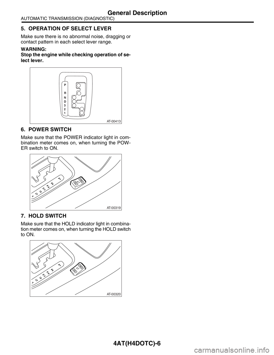
5. OPERATION OF SELECT LEVER
Make sure there is no abnormal noise, dragging or
contact pattern in each select lever range.
WARNING:
Stop the engine while checking operation of se-
lect lever.
6. POWER SWITCH
Make sure that the POWER indicator light in com-
bination meter comes on, when turning the POW-
ER switch to ON.
7. HOLD SWITCH
Make sure that the HOLD indicator light in combina-
tion meter comes on, when turning the HOLD switch
to ON.
AT-00413
P
R
N
D
3
2
1
AT-00319
AT-00320
Page 2593 of 2870
![SUBARU FORESTER 2004 Service Repair Manual 4AT(H4DOTC)-17
AUTOMATIC TRANSMISSION (DIAGNOSTIC)
Subaru Select Monitor
3. CLEAR MEMORY MODE
1) On the «Main Menu» display screen, select the
{2. Each System Check} and press the [YES] key.
2) On t SUBARU FORESTER 2004 Service Repair Manual 4AT(H4DOTC)-17
AUTOMATIC TRANSMISSION (DIAGNOSTIC)
Subaru Select Monitor
3. CLEAR MEMORY MODE
1) On the «Main Menu» display screen, select the
{2. Each System Check} and press the [YES] key.
2) On t](/manual-img/17/57426/w960_57426-2592.png)
4AT(H4DOTC)-17
AUTOMATIC TRANSMISSION (DIAGNOSTIC)
Subaru Select Monitor
3. CLEAR MEMORY MODE
1) On the «Main Menu» display screen, select the
{2. Each System Check} and press the [YES] key.
2) On the «System Selection Menu» display screen,
select the {Transmission Control System} and press
the [YES] key.
3) Press the [YES] key after the information of
transmission type is displayed.
4) On the «Transmission Diagnosis» display screen,
select the {Clear Memory} and press the [YES] key.
5) When the “Done” is shown on display screen,
turn the Subaru Select Monitor and ignition switch
to OFF.
NOTE:
For details concerning operation procedure, refer
to the SUBARU SELECT MONITOR OPERATION
MANUAL.
When {Clear Memory 2} is selected and executed,
DTC and learned control memory is cleared. If Clear
Memory 2 is performed, execute the learning con-
trol.
Select Monitor.>
4. FACILITATION OF LEARNING CON-
TROL
1) Shift the select lever to “P” range, and apply
parking brake.
2) Lift-up the vehicle.
3) Connect the Subaru Select Monitor to data link
connector, and then turn the ignition switch to ON.
4) Perform the {Clear Memory 2} using Subaru Select
Monitor.
5) Using Subaru Select Monitor, check that the DTC
is not output.
aru Select Monitor.>
6) Warm-up the engine until the ATF temperature
which is displayed on the Subaru Select Monitor is
within 60 — 90°C (140 — 194°F).
ERATION, Subaru Select Monitor.>
7) Shift the select lever to “R” range.
8) Turn all switches including headlight, air condi-
tioner, seat heater, rear defogger and etc. to OFF.
9) Turn the ignition switch to OFF.
10) Depress the brake pedal fully until the facilitation
of learning control is completed when the “Communi-
cation Failed!” is displayed on Subaru Select Monitor.
11) Turn the ignition switch to ON.
12) Check that the Subaru Select Monitor is re-
turned to normal operation.
13) Shift the select lever to “P” range, and then wait
for more than 3 seconds.14) Shift the select lever to “R” range, and then wait
for more than 3 seconds.
15) Shift the select lever to “N” range, and then wait
for more than 3 seconds.
16) Shift the select lever to “D” range, and then wait
for more than 3 seconds.
17) Shift the select lever to “N” range, and then wait
for more than 3 seconds.
18) Slightly depress the accelerator pedal fully.
19) Slightly release the accelerator pedal fully.
20) Start the engine, and idle it.
21) Shift the select lever to “D” range.
22) Start the facilitation of learning control. At this
time, the POWER indicator light in combination meter
blinks at 2 Hz. When the POWER indicator light does
not blink, turn the ignition switch to OFF and repeat
the procedures from step 4). When the POWER indi-
cator light which blinking at 2 Hz changes to blink at
0.5 Hz, facilitation of learning control is completed.
NOTE:
When blinking of POWER indicator light changes
from 2 Hz to 4 Hz during facilitation of learning con-
trol, repeat the procedure from step 4).
23) Shift the select lever to “N” range, and then turn
the ignition switch to OFF.
24) Shift the select lever to the “P” range, and then
complete the facilitation of learning control.
Page 2597 of 2870

4AT(H4DOTC)-21
AUTOMATIC TRANSMISSION (DIAGNOSTIC)
Power Indicator Light Display
10.Power Indicator Light Display
A: OPERATION
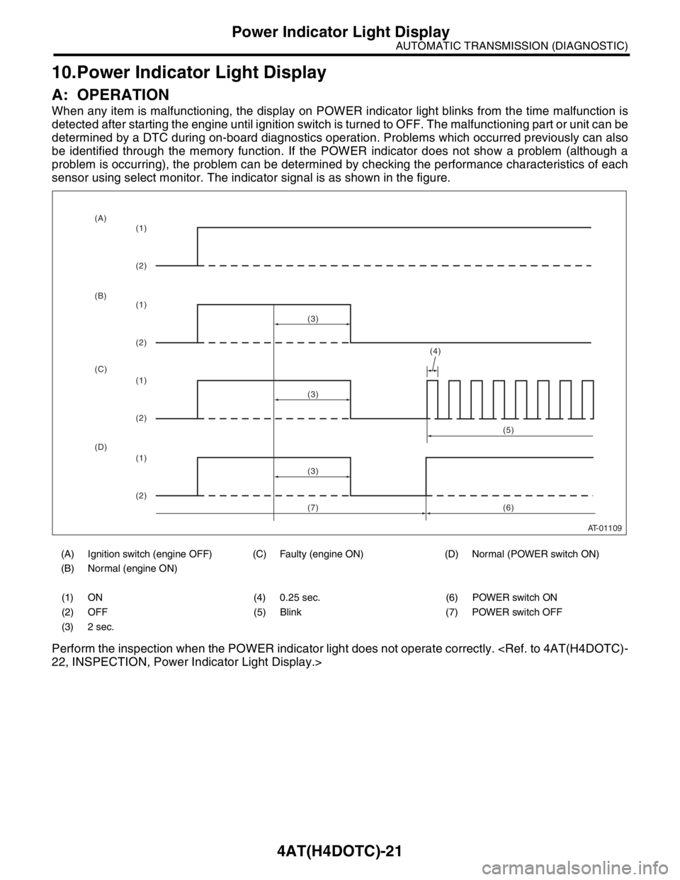
When any item is malfunctioning, the display on POWER indicator light blinks from the time malfunction is
detected after starting the engine until ignition switch is turned to OFF. The malfunctioning part or unit can be
determined by a DTC during on-board diagnostics operation. Problems which occurred previously can also
be identified through the memory function. If the POWER indicator does not show a problem (although a
problem is occurring), the problem can be determined by checking the performance characteristics of each
sensor using select monitor. The indicator signal is as shown in the figure.
Perform the inspection when the POWER indicator light does not operate correctly.
(A) Ignition switch (engine OFF) (C) Faulty (engine ON) (D) Normal (POWER switch ON)
(B) Normal (engine ON)
(1) ON (4) 0.25 sec. (6) POWER switch ON
(2) OFF (5) Blink (7) POWER switch OFF
(3) 2 sec.
AT-01109
(4)
(3)
(1)
(2)
(1)
(2)
(1)
(2)
(1)
(2)(3)
(3)(5)
(6) (A)
(B)
(C)
(D)
(7)
Page 2598 of 2870

4AT(H4DOTC)-22
AUTOMATIC TRANSMISSION (DIAGNOSTIC)
Power Indicator Light Display
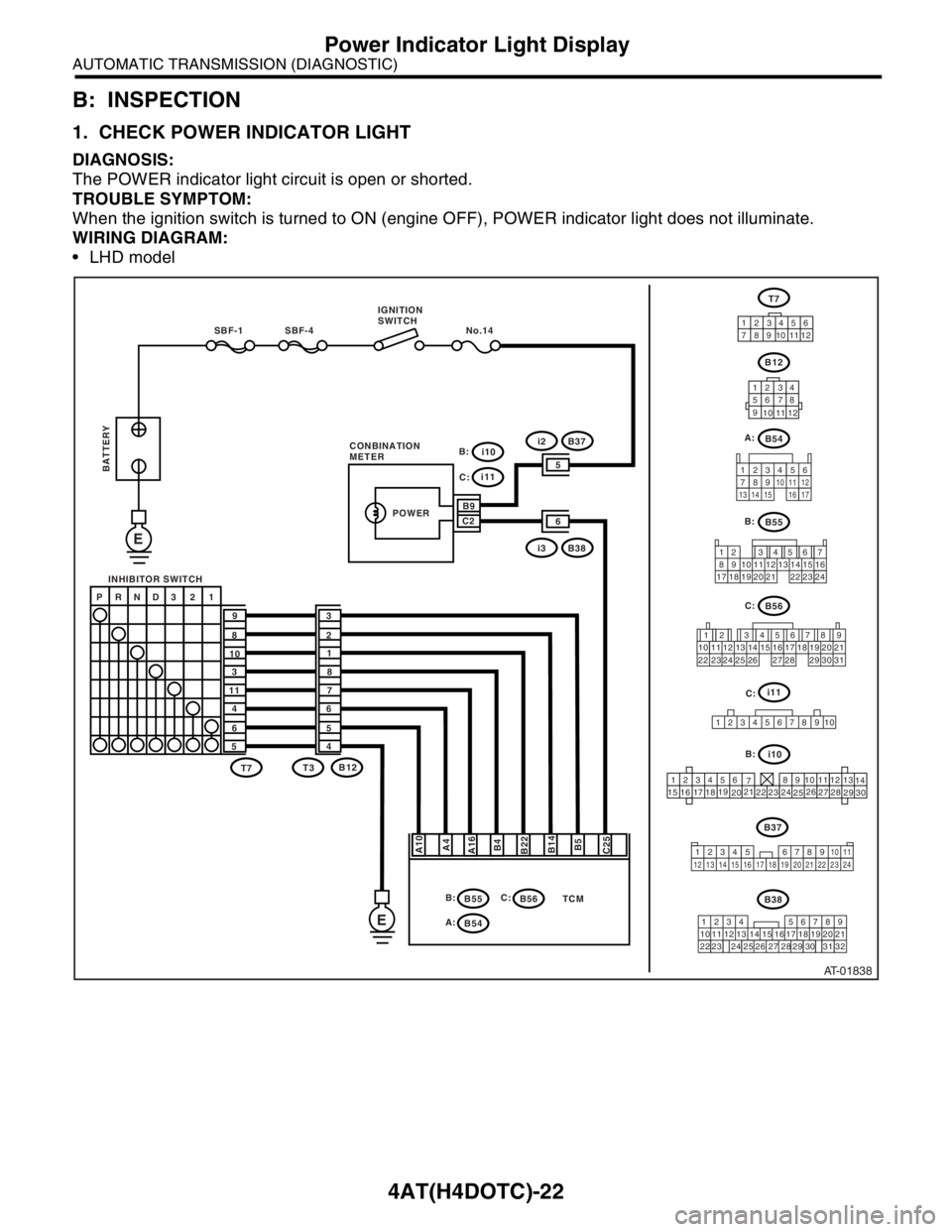
B: INSPECTION
1. CHECK POWER INDICATOR LIGHT
DIAGNOSIS:
The POWER indicator light circuit is open or shorted.
TROUBLE SYMPTOM:
When the ignition switch is turned to ON (engine OFF), POWER indicator light does not illuminate.
WIRING DIAGRAM:
LHD model
AT-01838
B55
B56
12 7
8956 34
10 11 12
19 20 2113 14 15 16
17 18 22 23 24
12 78 956 34
10 11 12 19 20 21
29 30 31 13 14 15 16 17
27 2818
22 23 24 25 26
TCM
SBF-4 No.14 SBF-1
E
E
A10
A4
A16
B4
B22
B5 B14
C25
P RND3 2 1
9
8
10
3
11
4
6
53
2
1
8
7
6
5
4
T7T7
B12
B55 T3B12
12 34
56 78
9
10
11
12
12 3456
789101112
123456
78 9 10 1112
13
14
15
1617
1819
2021
2223
24
2526
2728
29
30
i10
i11
B9
65
C2
i3B38
i2B37
POWER
B:
B54 A:
B56 C: B:
i10 B: C:
i11
C:
1234
5678910
C: B:
B54 A:
B38
219
32 1234 56
10 11 12 13 14 157
16
23 3019 20
22 26 27 28 298
17
24 3118
25
B37 IGNITION
SWITCH
INHIBITOR SWITCH
BATTERY
CONBINATION
METER
123
8910411 12
13 14 15 1656
7
17
34 12 8910 11
12 13 14 15 16 17 18 19 20 21 22 23 24567