2004 SUBARU FORESTER cooling
[x] Cancel search: coolingPage 34 of 2870
AC-32
HVAC SYSTEM (HEATER, VENTILATOR AND A/C)
Blower Motor Unit Assembly
7. Blower Motor Unit Assembly
A: REMOVAL
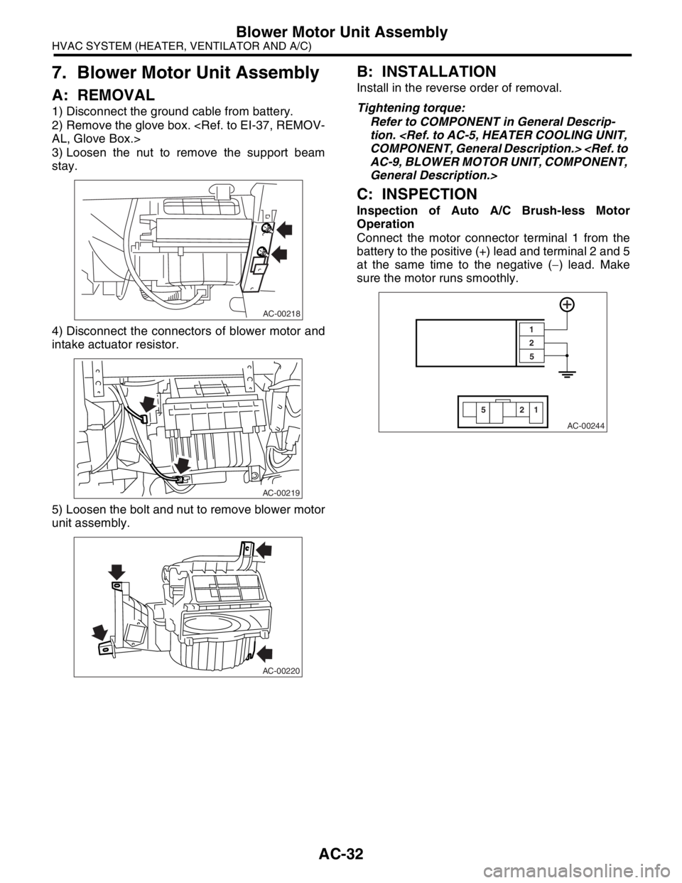
1) Disconnect the ground cable from battery.
2) Remove the glove box.
3) Loosen the nut to remove the support beam
stay.
4) Disconnect the connectors of blower motor and
intake actuator resistor.
5) Loosen the bolt and nut to remove blower motor
unit assembly.
B: INSTALLATION
Install in the reverse order of removal.
Tightening torque:
Refer to COMPONENT in General Descrip-
tion.
General Description.>
C: INSPECTION
Inspection of Auto A/C Brush-less Motor
Operation
Connect the motor connector terminal 1 from the
battery to the positive (+) lead and terminal 2 and 5
at the same time to the negative (−) lead. Make
sure the motor runs smoothly.
AC-00218
AC-00219
AC-00220
AC-00244
22
55
1 1
Page 36 of 2870
AC-34
HVAC SYSTEM (HEATER, VENTILATOR AND A/C)
Heater Core
9. Heater Core
A: REMOVAL
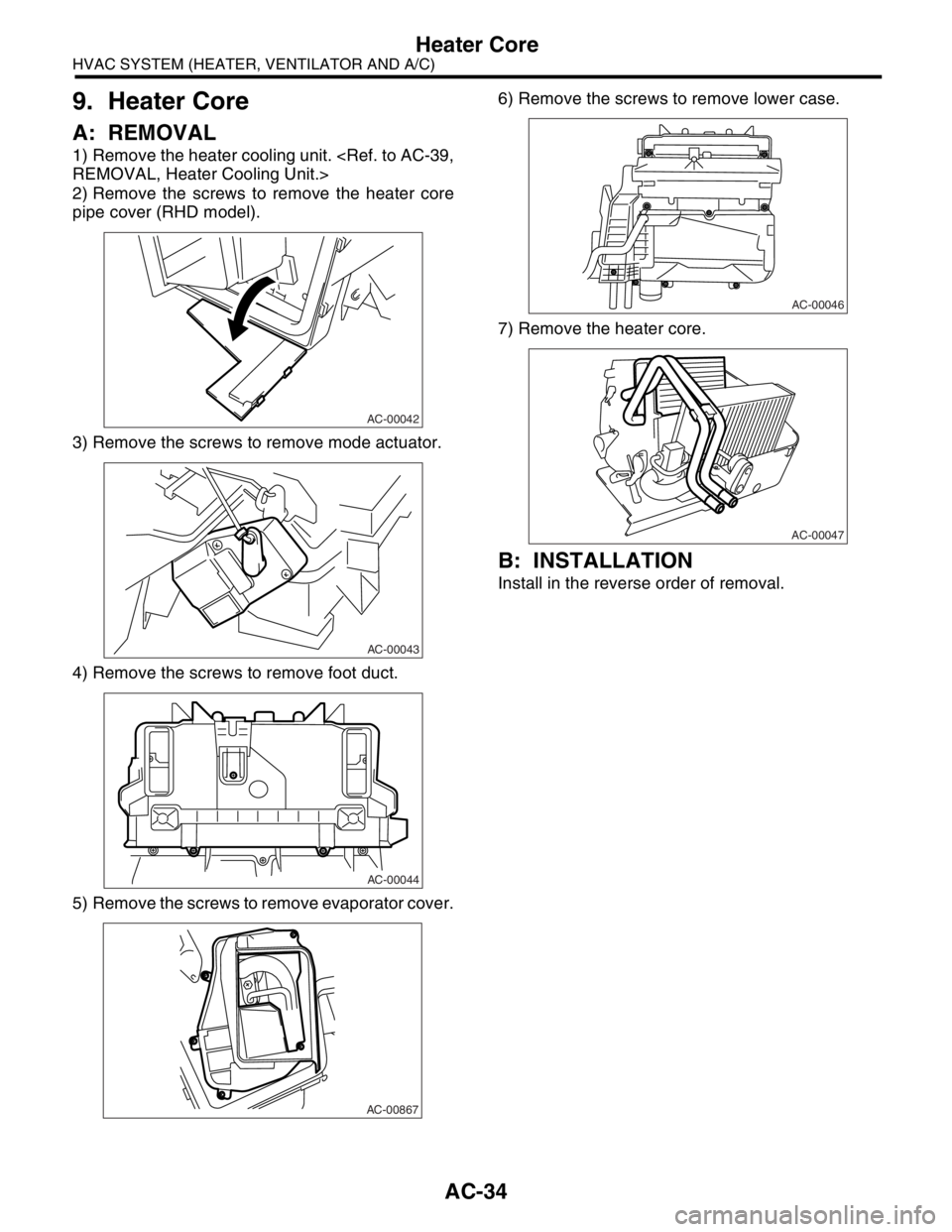
1) Remove the heater cooling unit.
2) Remove the screws to remove the heater core
pipe cover (RHD model).
3) Remove the screws to remove mode actuator.
4) Remove the screws to remove foot duct.
5) Remove the screws to remove evaporator cover.6) Remove the screws to remove lower case.
7) Remove the heater core.
B: INSTALLATION
Install in the reverse order of removal.
AC-00042
AC-00043
AC-00044
AC-00867
AC-00046
AC-00047
Page 41 of 2870
AC-39
HVAC SYSTEM (HEATER, VENTILATOR AND A/C)
Heater Cooling Unit
14.Heater Cooling Unit
A: REMOVAL
1) Disconnect the ground cable from battery.
2) Using the refrigerant recovery system, dis-
charge refrigerant.
3) Drain the engine coolant from radiator.
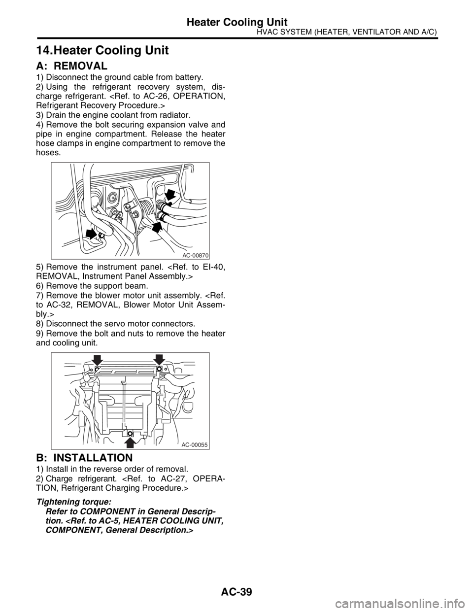
4) Remove the bolt securing expansion valve and
pipe in engine compartment. Release the heater
hose clamps in engine compartment to remove the
hoses.
5) Remove the instrument panel.
6) Remove the support beam.
7) Remove the blower motor unit assembly.
bly.>
8) Disconnect the servo motor connectors.
9) Remove the bolt and nuts to remove the heater
and cooling unit.
B: INSTALLATION
1) Install in the reverse order of removal.
2) Charge refrigerant.
Tightening torque:
Refer to COMPONENT in General Descrip-
tion.
AC-00870
AC-00055
Page 735 of 2870
PI-12
PRE-DELIVERY INSPECTION
Pre-delivery Inspection
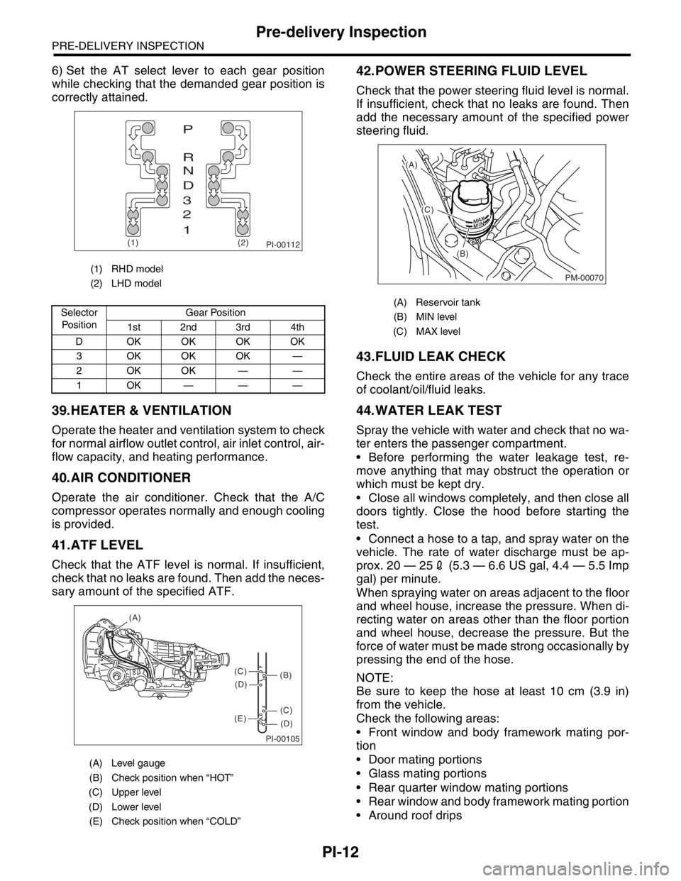
6) Set the AT select lever to each gear position
while checking that the demanded gear position is
correctly attained.
39.HEATER & VENTILATION
Operate the heater and ventilation system to check
for normal airflow outlet control, air inlet control, air-
flow capacity, and heating performance.
40.AIR CONDITIONER
Operate the air conditioner. Check that the A/C
compressor operates normally and enough cooling
is provided.
41.ATF LEVEL
Check that the ATF level is normal. If insufficient,
check that no leaks are found. Then add the neces-
sary amount of the specified ATF.
42.POWER STEERING FLUID LEVEL
Check that the power steering fluid level is normal.
If insufficient, check that no leaks are found. Then
add the necessary amount of the specified power
steering fluid.
43.FLUID LEAK CHECK
Check the entire areas of the vehicle for any trace
of coolant/oil/fluid leaks.
44.WATER LEAK TEST
Spray the vehicle with water and check that no wa-
ter enters the passenger compartment.
Before performing the water leakage test, re-
move anything that may obstruct the operation or
which must be kept dry.
Close all windows completely, and then close all
doors tightly. Close the hood before starting the
test.
Connect a hose to a tap, and spray water on the
vehicle. The rate of water discharge must be ap-
prox. 20 — 252 (5.3 — 6.6 US gal, 4.4 — 5.5 Imp
gal) per minute.
When spraying water on areas adjacent to the floor
and wheel house, increase the pressure. When di-
recting water on areas other than the floor portion
and wheel house, decrease the pressure. But the
force of water must be made strong occasionally by
pressing the end of the hose.
NOTE:
Be sure to keep the hose at least 10 cm (3.9 in)
from the vehicle.
Check the following areas:
Front window and body framework mating por-
tion
Door mating portions
Glass mating portions
Rear quarter window mating portions
Rear window and body framework mating portion
Around roof drips
(1) RHD model
(2) LHD model
Selector
Po si t io nGear Position
1st 2nd 3rd 4th
D OKOKOKOK
3 OKOKOK —
2OKOK——
1OK———
(A) Level gauge
(B) Check position when “HOT”
(C) Upper level
(D) Lower level
(E) Check position when “COLD”
PI-00112(1) (2)
P
R
N
D
3
2
1
PI-00105
COLD
LFHOT LF
(A)
(C)
(D)
(C)
(D)
(E)
(B)
(A) Reservoir tank
(B) MIN level
(C) MAX level
PM-00070
(A)
(C)
(B)
Page 738 of 2870

PERIODIC MAINTENANCE SERVICE
PM
Page
1. General Description ....................................................................................2
2. Schedule .....................................................................................................3
3. Engine Oil....................................................................................................7
4. Engine Oil Filter...........................................................................................9
5. Spark Plugs ...............................................................................................10
6. V-belt .........................................................................................................11
7. Timing Belt ................................................................................................13
8. Fuel Line ...................................................................................................17
9. Fuel Filter ..................................................................................................18
10. Air Cleaner Element ..................................................................................19
11. Cooling System .........................................................................................20
12. Engine Coolant..........................................................................................21
13. Clutch System ...........................................................................................23
14. Transmission Gear Oil ..............................................................................24
15. Hill-holder System .....................................................................................25
16. ATF ...........................................................................................................26
17. Front & Rear Differential Oil ......................................................................28
18. Brake Line .................................................................................................30
19. Brake Fluid ................................................................................................32
20. Disc Brake Pads and Discs .......................................................................33
21. Brake Linings and Drums ..........................................................................34
22. Suspension ...............................................................................................36
23. Wheel Bearing...........................................................................................38
24. Axle Boots & Joints ...................................................................................39
25. Tire Rotation..............................................................................................40
26. Steering System (Power Steering) ............................................................41
Page 740 of 2870

PM-3
PERIODIC MAINTENANCE SERVICE
Schedule
2. Schedule
A: MAINTENANCE SCHEDULE 1
1. FOR EUROPE AREA
For periodic maintenance of over 120,000 km (75,000 miles) or 96 months, carry out inspection by referring
to the following table. For a maintenance period gone beyond these tables, apply them repeatedly as a set
of 120,000 km (75,000 miles) or 96 months.
Symbols used:
R: Replace
I: Inspection
(I): Recommended service for safe vehicle operation.
N
OTE:
(1) When the vehicle is used in extremely dusty conditions, the air cleaner element should be replaced more often.
(2) ATF filter is a maintenance free part. ATF filter needs replacement, when it is physically damaged or ATF leaked.Maintenance interval
[Number of months or km (miles), whichever occurs first]
Month 1224364860728496
Remarks ×1,000 km 1.6 5 15 30 45 60 75 90 105 120
×1,000 miles 1 3 9 19 28 38 47 56 66 75
1Engine oil RRRRRRRR
2Engine oil filter RRRRRRRR
3 Spark plug For Turbo R
Others RRRR
4Drive belt(s) IIIIIIII
5Camshaft drive belt RRRR
6Fuel line IIII
7 Fuel filter R R
8 Air cleaner element I R I R I R I R
9Cooling system IIII
10Coolant RRRR
11Clutch system IIII
12Hill-holder system IIII
13 Transmission oil I R I R
14 ATF I R I R
15 Front & rear differential I R I R
16Brake line IIII
17Brake fluid RRRR
18Disk brake pads & discs IIIIIIII
19Brake linings & drums IIII
20Parking brake IIII
21Suspension IIII
22 Wheel bearing(I)
23Axle boot & joint IIIIIIII
24Steering system IIII
Page 741 of 2870

PM-4
PERIODIC MAINTENANCE SERVICE
Schedule
2. EXCEPT FOR EUROPE AREA
For periodic maintenance of over 50,000 km (30,000 miles) or 48 months, carry out inspections by referring
to the following tables. For a maintenance period gone beyond these tables, apply them repeatedly as a set
of 50,000 km (30,000 miles) or 48 months.
For periodic maintenance of over 100,000 km (60,000 miles) or 48 months, carry out inspections by referring
to the following tables. For a maintenance period gone beyond these tables, apply them repeatedly as a set
of 100,000 km (60,000 miles) or 48 months.
Symbols used:
R: Replace
I: Inspection
(I): Recommended service for safe vehicle operation.
N
OTE:
(1) When the vehicle is used in extremely dusty conditions, the air cleaner element should be replaced more often.
(2) ATF filter is a maintenance free part. ATF filter needs replacement, when it is physically damaged or ATF leaked.Maintenance Interval
[Number of months or km (miles), whichever occurs first]
Months 12 24 36 48
Remarks ×1,000 km 5 12.5 25 37.5 50
×1,000 miles 3 7.5 15 22.5 30
1 Engine oil R R R R
2 Engine oil filter R R R R
Maintenance Interval
[Number of months or km (miles), whichever occurs first]
Months 12 24 36 48
Remarks ×1,000 km 1.6 25 50 75 100
×1,000 miles 1 15 30 45 60
3 Spark plugs For Turbo R
Others R R R R
4Drive belt(s) IIII
5 Camshaft drive belt R
6 Fuel line I I
7 Fuel filter R R
8 Air cleaner element I R I R
9 Cooling system I I
10 Coolant R R
11 Clutch system I I I I I
12 Hill-holder system I I I I I
13 Transmission oil R R
14 ATF R R
15 Front & rear differential oil R R
16 Brake line I I
17 Brake fluid R R
18 Disc brake pads & discs I I I I
19 Brake linings and drums I I
20 Parking brake I I I I
21 Suspension I I I I
22 Wheel bearing (I)
23 Axle boots & joints I I I I
24 Steering system (Power steering) I I I I
Page 757 of 2870
PM-20
PERIODIC MAINTENANCE SERVICE
Cooling System
11.Cooling System
A: INSPECTION
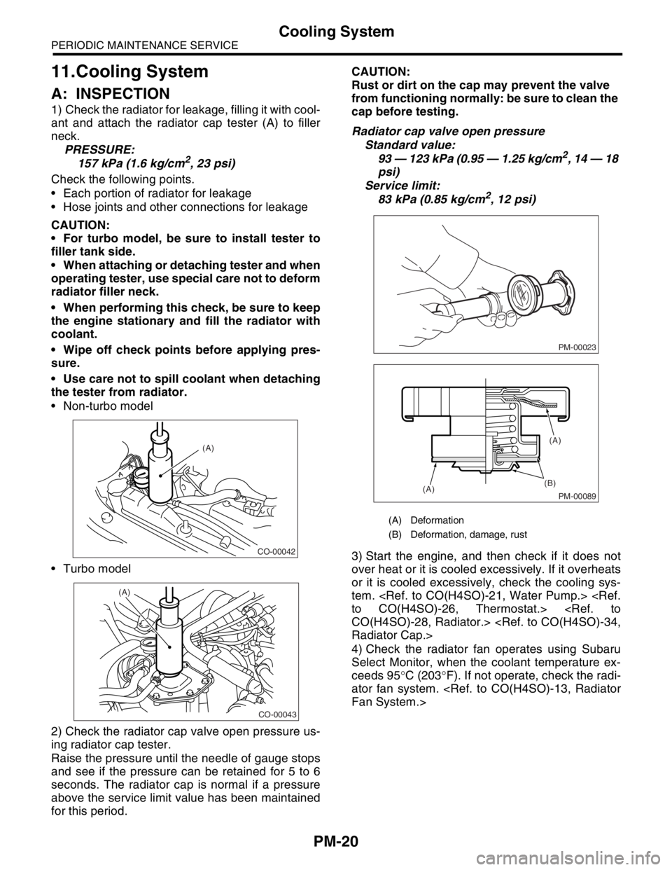
1) Check the radiator for leakage, filling it with cool-
ant and attach the radiator cap tester (A) to filler
neck.
PRESSURE:
157 kPa (1.6 kg/cm
2, 23 psi)
Check the following points.
Each portion of radiator for leakage
Hose joints and other connections for leakage
CAUTION:
For turbo model, be sure to install tester to
filler tank side.
When attaching or detaching tester and when
operating tester, use special care not to deform
radiator filler neck.
When performing this check, be sure to keep
the engine stationary and fill the radiator with
coolant.
Wipe off check points before applying pres-
sure.
Use care not to spill coolant when detaching
the tester from radiator.
Non-turbo model
Turbo model
2) Check the radiator cap valve open pressure us-
ing radiator cap tester.
Raise the pressure until the needle of gauge stops
and see if the pressure can be retained for 5 to 6
seconds. The radiator cap is normal if a pressure
above the service limit value has been maintained
for this period.CAUTION:
Rust or dirt on the cap may prevent the valve
from functioning normally: be sure to clean the
cap before testing.
Radiator cap valve open pressure
Standard value:
93 — 123 kPa (0.95 — 1.25 kg/cm2, 14 — 18
psi)
Service limit:
83 kPa (0.85 kg/cm
2, 12 psi)
3) Start the engine, and then check if it does not
over heat or it is cooled excessively. If it overheats
or it is cooled excessively, check the cooling sys-
tem.
4) Check the radiator fan operates using Subaru
Select Monitor, when the coolant temperature ex-
ceeds 95°C (203°F). If not operate, check the radi-
ator fan system.
CO-00042
(A)
CO-00043
(A)
(A) Deformation
(B) Deformation, damage, rust
PM-00023
PM-00089
(B)
(A)(A)