2004 SUBARU FORESTER fuel pump
[x] Cancel search: fuel pumpPage 2084 of 2870

EN(H4DOTC 2.5)-60
ENGINE (DIAGNOSTIC)
Diagnostics for Engine Starting Failure
Step Check Yes No
1 CHECK SPARK PLUG CONDITION.
1) Remove the spark plug.
2) Check the spark plug condition.
plug.
2 CHECK IGNITION SYSTEM FOR SPARKS.
1) Connect the spark plug to ignition coil.
2) Release the fuel pressure.
PRESSURE, OPERATION, Fuel.>
3) Contact the spark plug’s thread portion on
engine.
4) While opening the throttle valve fully, crank
the engine to check that spark occurs at each
cylinder.Does spark occur at each cyl-
inder?Check fuel pump
system.
62, FUEL PUMP
CIRCUIT, Diag-
nostics for Engine
Starting Failure.>Go to step 3.
3 CHECK POWER SUPPLY CIRCUIT FOR IG-
NITION COIL & IGNITOR ASSY.
1) Turn the ignition switch to OFF.
2) Disconnect the connector from ignition coil
& ignitor ASSY.
3) Turn the ignition switch to ON.
4) Measure the power supply voltage between
ignition coil & ignitor ASSY connector and
engine ground.
Connector & terminal
(E31) No. 3 (+) — Engine ground (
−):
(E32) No. 3 (+) — Engine ground (
−):
(E33) No. 3 (+) — Engine ground (
−):
(E34) No. 3 (+) — Engine ground (
−):Is the voltage more than 10 V? Go to step 4.Repair the harness
and connector.
N
OTE:
In this case repair
the following:
Open circuit in
harness between
ignition coil & igni-
tor ASSY, and igni-
tion switch
connector
Poor contact in
coupling connector
4 CHECK HARNESS OF IGNITION COIL & IG-
NITOR ASSY GROUND CIRCUIT.
1) Turn the ignition switch to OFF.
2) Measure the resistance between ignition
coil & ignitor ASSY connector and engine
ground.
Connector & terminal
(E31) No. 2 — Engine ground:
(E32) No. 2 — Engine ground:
(E33) No. 2 — Engine ground:
(E34) No. 2 — Engine ground:Is the resistance less than 5
Ω?Go to step 5.Repair the harness
and connector.
N
OTE:
In this case repair
the following:
Open circuit in
harness between
ignition coil & igni-
tor ASSY connec-
tor and engine
ground terminal
5 CHECK HARNESS BETWEEN ECM AND IG-
NITION COIL & IGNITOR ASSY CONNEC-
TOR.
1) Turn the ignition switch to OFF.
2) Disconnect the connector from ECM.
3) Disconnect the connector from ignition coil
& ignitor ASSY.
4) Measure the resistance of harness
between ECM and ignition coil & ignitor ASSY
connector.
Connector & terminal
(B135) No. 15 — (E34) No. 1:
(B135) No. 16 — (E33) No. 1:
(B135) No. 17 — (E32) No. 1:
(B135) No. 18 — (E31) No. 1:Is the resistance less than 1
Ω?Go to step 6.Repair the harness
and connector.
N
OTE:
In this case repair
the following:
OPEN CIR-
CUIT IN HAR-
NESS BETWEEN
ECM AND IGNI-
TION COIL &
IGNITOR ASSY
CONNECTOR.
Poor contact in
coupling connector
Page 2085 of 2870

EN(H4DOTC 2.5)-61
ENGINE (DIAGNOSTIC)
Diagnostics for Engine Starting Failure
6 CHECK HARNESS BETWEEN ECM AND IG-
NITION COIL & IGNITOR ASSY CONNEC-
TOR.
Measure the resistance of harness between
ECM and engine ground.
Connector & terminal
(B135) No. 15 — Engine ground:
(B135) No. 16 — Engine ground:
(B135) No. 17 — Engine ground:
(B135) No. 18 — Engine ground:Is the resistance more than 1
MΩ?Go to step 7.Repair ground
short circuit in har-
ness between
ECM and ignition
coil & ignitor ASSY
connector.
7 CHECK POOR CONTACT.
Check poor contact in ECM connector.Is there poor contact in ECM
connector?Repair the poor
contact in ECM
connector.Check fuel pump
circuit.
62, FUEL PUMP
CIRCUIT, Diag-
nostics for Engine
Starting Failure.> Step Check Yes No
Page 2086 of 2870
EN(H4DOTC 2.5)-62
ENGINE (DIAGNOSTIC)
Diagnostics for Engine Starting Failure
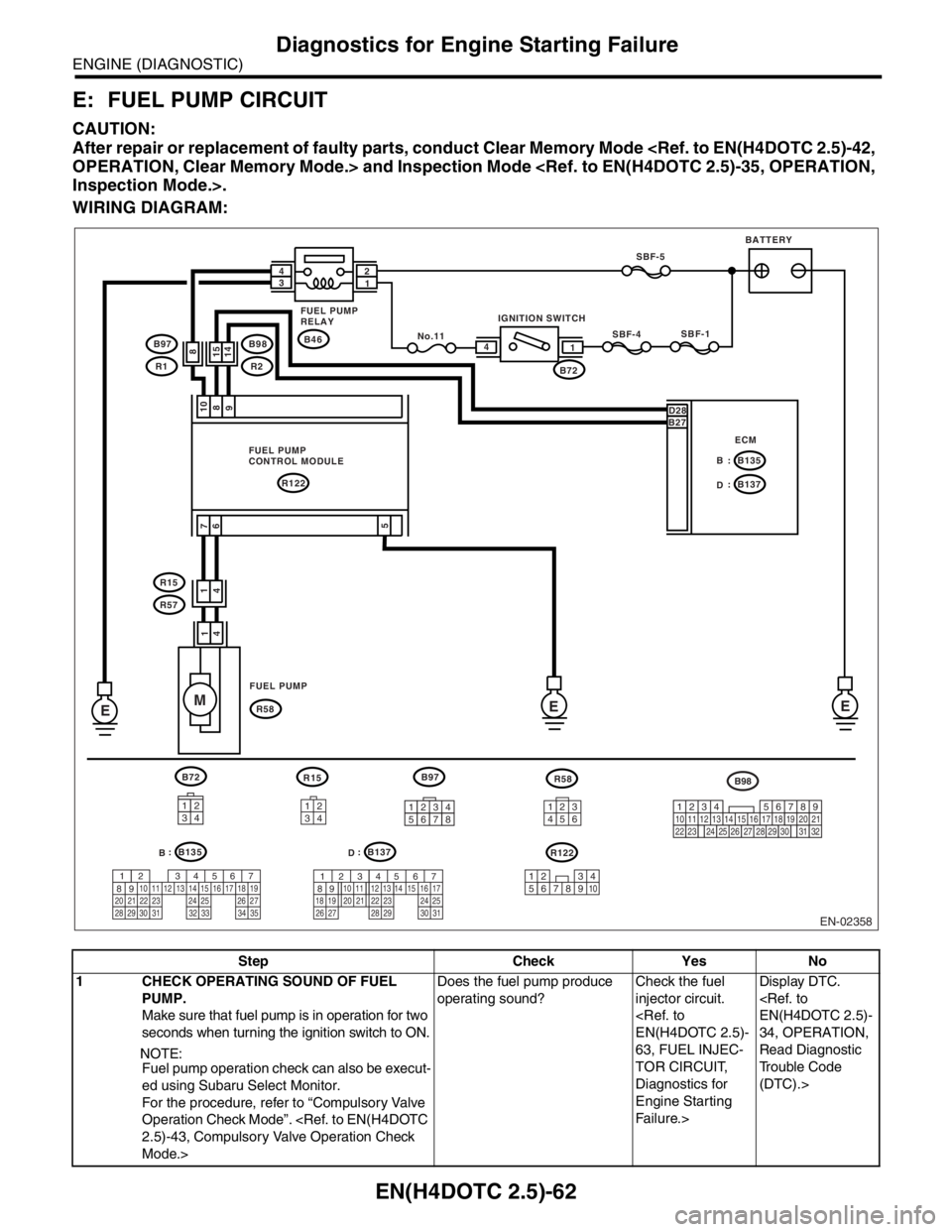
E: FUEL PUMP CIRCUIT
CAUTION:
After repair or replacement of faulty parts, conduct Clear Memory Mode
WIRING DIAGRAM:
Step Check Yes No
1 CHECK OPERATING SOUND OF FUEL
PUMP.
Make sure that fuel pump is in operation for two
seconds when turning the ignition switch to ON.
NOTE:
Fuel pump operation check can also be execut-
ed using Subaru Select Monitor.
For the procedure, refer to “Compulsory Valve
Operation Check Mode”.
Mode.>Does the fuel pump produce
operating sound?Check the fuel
injector circuit.
63, FUEL INJEC-
TOR CIRCUIT,
Diagnostics for
Engine Starting
Fa il u r e. >Display DTC.
34, OPERATION,
Read Diagnostic
Trouble Code
(DTC).>
EN-02358
R15
E
E M
R122: B135 B
: B137
D
R58
B97 B97
3412
B98 R1
R15
R57
567
82 1
94 310
24 22 23 2511 12 13 14 15
26 27
2816 17 18 19
20 21
29 30 31 32 33 34 35567
82 1
94 310
22 23 11 12 13 14 15
24 25
2616 17
18 19 20 21
27 28 29 30 31
R122
3
4 12
5891067
FUEL PUMP
CONTROL MODULE
FUEL PUMPECMBATTERY
B72SBF-1
SBF-4
D28
B27
E
98 10
7
6 1
4 1
415
14
1 4
5
IGNITION SWITCH
B46 FUEL PUMP
RELAY
2
1 4
3SBF-5
No.118B98
R2
12345678219
32
1234
5610 11 12 13 14 15716
23 3019 20
22 26 27 28 29817
24 3118
25
: B135
B: B137
D
B72
3412
R58
23
56 1
4
Page 2087 of 2870
EN(H4DOTC 2.5)-63
ENGINE (DIAGNOSTIC)
Diagnostics for Engine Starting Failure
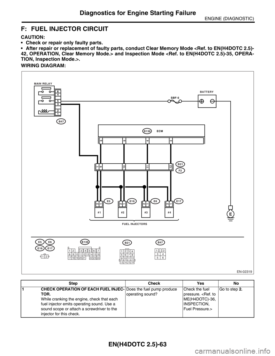
F: FUEL INJECTOR CIRCUIT
CAUTION:
Check or repair only faulty parts.
After repair or replacement of faulty parts, conduct Clear Memory Mode
WIRING DIAGRAM:
Step Check Yes No
1 CHECK OPERATION OF EACH FUEL INJEC-
TOR.
While cranking the engine, check that each
fuel injector emits operating sound. Use a
sound scope or attach a screwdriver to the
injector for this check.Does the fuel pump produce
operating sound?Check the fuel
pressure.
INSPECTION,
Fuel Pressure.>Go to step 2.
EN-02319
BATTERY
FUEL INJECTORS MAIN RELAY
E#4
1 2
SBF-5
#3
1
2
#2
1 2
#1
1
2
1
9
10
11
12
12
12
7
8956 3410 11 12
19 20 2113 14 1516
17 1822
23
24123
4
56
78
9
1011 12
1314 15 16
6
4
5
3
2
1
B21
B21B136E5
E5
F2
E6
E6
E16
E16
E17
B47
E17
6
5
4
3
B136ECM
B47
34
12
56
Page 2090 of 2870

EN(H4DOTC 2.5)-66
ENGINE (DIAGNOSTIC)
List of Diagnostic Trouble Code (DTC)
P0137 O2 Sensor Circuit Low Voltage
(Bank 1 Sensor 2)
Trouble Code (DTC).>
P0138 O
2 Sensor Circuit High Voltage
(Bank 1 Sensor 2)
Trouble Code (DTC).>
P0171 System Too Lean (Bank 1)
P0172 System Too Rich (Bank 1)
P0222 Throttle/Pedal Position Sensor/
Switch “B” Circuit Low Input
Diagnostic Trouble Code (DTC).>
P0223 Throttle/Pedal Position Sensor/
Switch “B” Circuit High Input
Diagnostic Trouble Code (DTC).>
P0230 Fuel Pump Primary Circuit
P0245 Turbo/Super Charger Wastegate
Solenoid “A” Low
Trouble Code (DTC).>
P0246 Turbo/Super Charger Wastegate
Solenoid “A” High
Trouble Code (DTC).>
P0327 Knock Sensor 1 Circuit Low Input
(Bank 1 or Single Sensor)
Diagnostic Trouble Code (DTC).>
P0328 Knock Sensor 1 Circuit High Input
(Bank 1 or Single Sensor)
Diagnostic Trouble Code (DTC).>
P0335 Crankshaft Position Sensor “A” Cir-
cuit
(DTC).>
P0340 Camshaft Position Sensor “A” Cir-
cuit (Bank 1 or Single Sensor)
with Diagnostic Trouble Code (DTC).>
P0345 Camshaft Position Sensor “A” Cir-
cuit (Bank 2)
Code (DTC).>
P0458 Evaporative Emission Control Sys-
tem Purge Control Valve Circuit Low
Procedure with Diagnostic Trouble Code (DTC).>
P0459 Evaporative Emission Control Sys-
tem Purge Control Valve Circuit High
tic Procedure with Diagnostic Trouble Code (DTC).>
P0462 Fuel Level Sensor Circuit Low
Input
(DTC).>
P0463 Fuel Level Sensor Circuit High
Input
(DTC).>
P0502 Vehicle Speed Sensor Circuit Low
Input
(DTC).>
P0503 Vehicle Speed Sensor Intermittent/
Erratic/High
ble Code (DTC).> DTC Item NOTE
Page 2139 of 2870

EN(H4DOTC 2.5)-115
ENGINE (DIAGNOSTIC)
Diagnostic Procedure with Diagnostic Trouble Code (DTC)
T: DTC P0171 SYSTEM TOO LEAN (BANK 1)
NOTE:
For diagnostic procedure, refer to DTC P0172.
U: DTC P0172 SYSTEM TOO RICH (BANK 1)
DTC DETECTING CONDITION:
Two consecutive driving cycles with fault
TROUBLE SYMPTOM:
Erroneous idling
Engine stalls.
Poor driving performance
CAUTION:
After repair or replacement of faulty parts, conduct Clear Memory Mode
Step Check Yes No
1 CHECK EXHAUST SYSTEM.Are there holes or loose bolts
on exhaust system?Repair exhaust
system.Go to step 2.
2 CHECK AIR INTAKE SYSTEM.Are there holes, loose bolts or
disconnection of hose on air
intake system?Repair air intake
system.Go to step 3.
3 CHECK FUEL PRESSURE.
Warning:
Place “NO FIRE” signs near the working
area.
Be careful not to spill fuel.
1) Release the fuel pressure.
(1) Disconnect the connector from fuel
pump relay.
(2) Start the engine and run it until it stalls.
(3) After the engine stalls, crank it for five
more seconds.
(4) Turn the ignition switch to OFF.
2) Connect the connector to fuel pump relay.
3) Disconnect the fuel delivery hose from fuel
filter, and connect the fuel pressure gauge.
4) Install the fuel filler cap.
5) Start the engine and idle while gear posi-
tion is neutral.
6) Measure the fuel pressure while discon-
necting pressure regulator vacuum hose from
intake manifold.
Warning:
Release fuel pressure before removing the
fuel pressure gauge.
N
OTE:
If fuel pressure does not increase, squeeze the
fuel return hose 2 to 3 times, then measure fuel
pressure again.Is measured value 284 — 314
kPa (2.9 — 3.2 kg/cm
2, 41 —
46 psi)?Go to step 4.Repair the follow-
ing items.
Fuel pressure is
too high:
Clogged fuel
return line or
bent hose
Fuel pressure is
too low:
Improper fuel
pump discharge
Clogged fuel
supply line
Page 2140 of 2870

EN(H4DOTC 2.5)-116
ENGINE (DIAGNOSTIC)
Diagnostic Procedure with Diagnostic Trouble Code (DTC)
4 CHECK FUEL PRESSURE.
After connecting the pressure regulator vac-
uum hose, measure fuel pressure.
Warning:
Release fuel pressure before removing the
fuel pressure gauge.
N
OTE:
If fuel pressure does not increase, squeeze
fuel return hose 2 to 3 times, then measure
fuel pressure again.
If out of specification as measured at this
step, check or replace pressure regulator and
pressure regulator vacuum hose.Is measured value 206 — 235
kPa (2.1 — 2.4 kg/cm
2, 30 —
34 psi)?Go to step 5.Repair the follow-
ing items.
Fuel pressure is
too high:
Faulty pres-
sure regulator
Clogged fuel
return line or
bent hose
Fuel pressure is
too low:
Faulty pres-
sure regulator
Improper fuel
pump discharge
Clogged fuel
supply line
5 CHECK ENGINE COOLANT TEMPERATURE
SENSOR.
1) Start the engine and warm-up completely.
2) Read the data of engine coolant tempera-
ture sensor signal using Subaru Select Monitor
or the OBD-II general scan tool.
NOTE:
Subaru Select Monitor
For detailed operation procedure, refer to
“READ CURRENT DATA SHOWN ON DIS-
PLAY FOR ENGINE”.
OBD-II general scan tool
For detailed operation procedures, refer to the
OBD-II General Scan Tool Operation Manual.Is engine coolant temperature
more than 60°C (140°F)?Go to step 6.Replace the
engine coolant
temperature sen-
sor.
26, Engine Cool-
ant Temperature
Sensor.>
6 CHECK MASS AIR FLOW AND INTAKE AIR
TEMPERATURE SENSOR
1) Start and warm-up the engine until engine
coolant temperature is greater than 60°C
(140°F).
2) Place the shift lever in neutral position.
3) Turn the A/C switch to OFF.
4) Turn all accessory switches to OFF.
5) Read the data of mass air flow and intake
air temperature sensor signal using Subaru
Select Monitor or the OBD-II general scan tool.
N
OTE:
Subaru Select Monitor
For detailed operation procedure, refer to
“READ CURRENT DATA SHOWN ON DIS-
PLAY FOR ENGINE”.
OBD-II general scan tool
For detailed operation procedures, refer to the
OBD-II General Scan Tool Operation Manual.Is the measured value within
the following?
Ignition ON: 73.3 — 106.6 kPa
(550 — 800 mmHg, 21.65 —
31.50 inHg) Idling: 24.0 — 41.3
kPa (180 — 310 mmHg, 7.09
— 12.20 inHg)Go to step 7.Replace the mass
air flow and intake
air temperature
sensor.
30, Mass Air Flow
and Intake Air
Temperature Sen-
sor.> Step Check Yes No
Page 2148 of 2870

EN(H4DOTC 2.5)-124
ENGINE (DIAGNOSTIC)
Diagnostic Procedure with Diagnostic Trouble Code (DTC)
X: DTC P0230 FUEL PUMP PRIMARY CIRCUIT
DTC DETECTING CONDITION:
Immediately at fault recognition
CAUTION:
After repair or replacement of faulty parts, conduct Clear Memory Mode
WIRING DIAGRAM:
EN-02358
R15
E
E M
R122: B135 B
: B137
D
R58
B97 B97
3412
B98 R1
R15
R57
567
82 1
94 310
24 22 23 2511 12 13 14 15
26 27
2816 17 18 19
20 21
29 30 31 32 33 34 35567
82 1
94 310
22 23 11 12 13 14 15
24 25
2616 17
18 19 20 21
27 28 29 30 31
R122
3
4 12
5891067
FUEL PUMP
CONTROL MODULE
FUEL PUMPECMBATTERY
B72SBF-1
SBF-4
D28
B27
E
98 10
7
6 1
4 1
415
14
1 4
5
IGNITION SWITCH
B46 FUEL PUMP
RELAY
2
1 4
3SBF-5
No.118B98
R2
12345678219
32
1234
5610 11 12 13 14 15716
23 3019 20
22 26 27 28 29817
24 3118
25
: B135
B: B137
D
B72
3412
R58
23
56 1
4