2004 SUBARU FORESTER cooling
[x] Cancel search: coolingPage 2010 of 2870
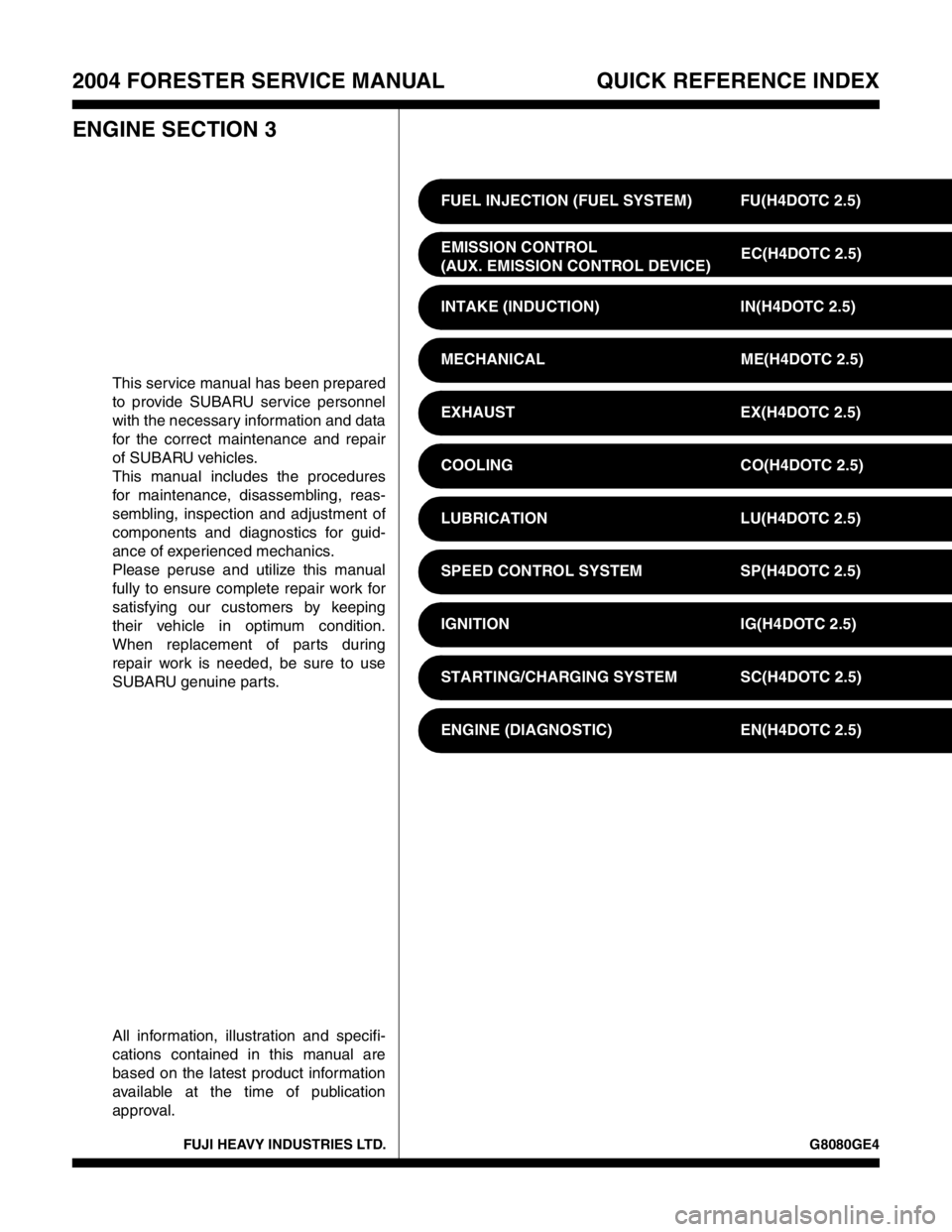
FUJI HEAVY INDUSTRIES LTD. G8080GE4
2004 FORESTER SERVICE MANUAL QUICK REFERENCE INDEX
ENGINE SECTION 3
This service manual has been prepared
to provide SUBARU service personnel
with the necessary information and data
for the correct maintenance and repair
of SUBARU vehicles.
This manual includes the procedures
for maintenance, disassembling, reas-
sembling, inspection and adjustment of
components and diagnostics for guid-
ance of experienced mechanics.
Please peruse and utilize this manual
fully to ensure complete repair work for
satisfying our customers by keeping
their vehicle in optimum condition.
When replacement of parts during
repair work is needed, be sure to use
SUBARU genuine parts.
All information, illustration and specifi-
cations contained in this manual are
based on the latest product information
available at the time of publication
approval.FUEL INJECTION (FUEL SYSTEM) FU(H4DOTC 2.5)
EMISSION CONTROL
(AUX. EMISSION CONTROL DEVICE)EC(H4DOTC 2.5)
INTAKE (INDUCTION) IN(H4DOTC 2.5)
MECHANICAL ME(H4DOTC 2.5)
EXHAUST EX(H4DOTC 2.5)
COOLING CO(H4DOTC 2.5)
LUBRICATION LU(H4DOTC 2.5)
SPEED CONTROL SYSTEM SP(H4DOTC 2.5)
IGNITION IG(H4DOTC 2.5)
STARTING/CHARGING SYSTEM SC(H4DOTC 2.5)
ENGINE (DIAGNOSTIC) EN(H4DOTC 2.5)
Page 2013 of 2870
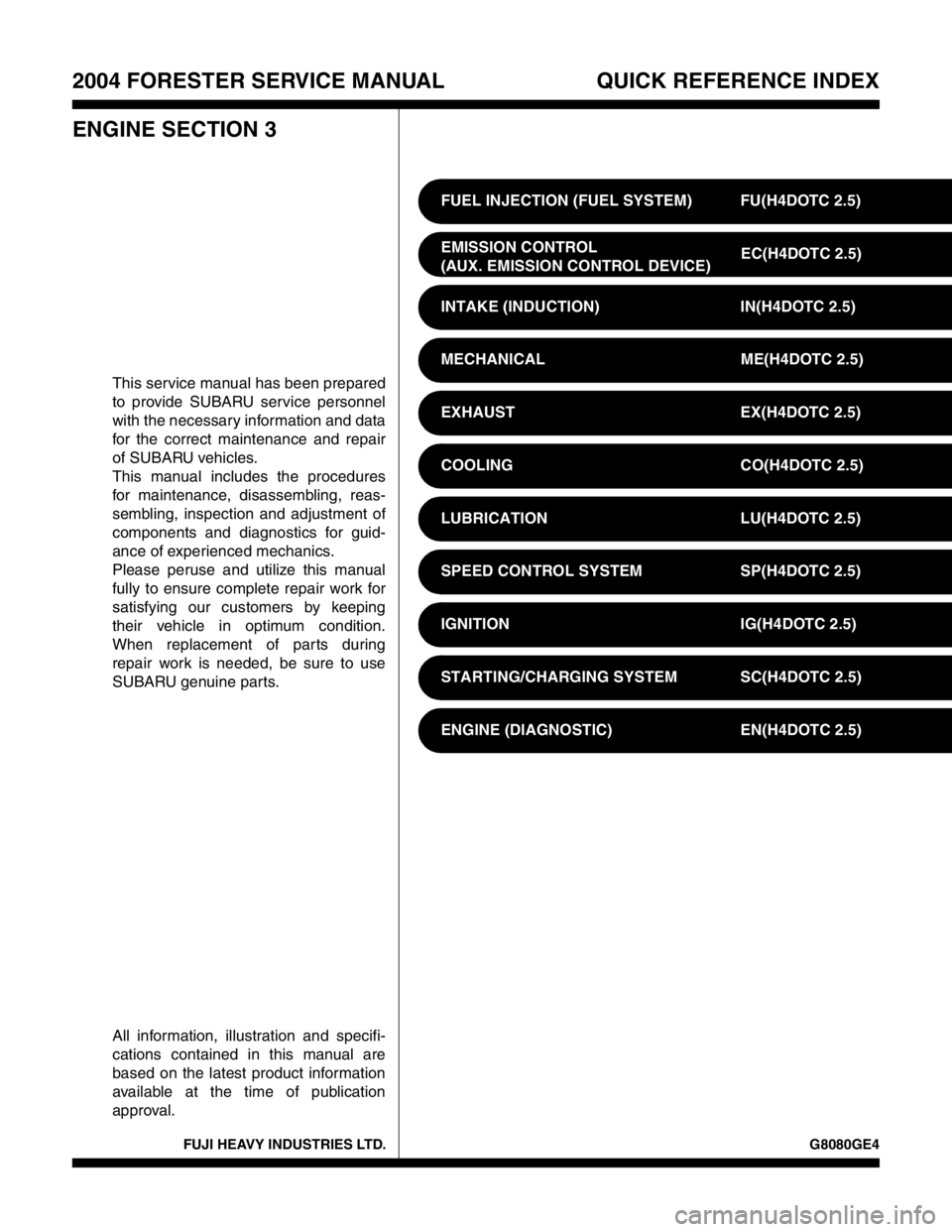
FUJI HEAVY INDUSTRIES LTD. G8080GE4
2004 FORESTER SERVICE MANUAL QUICK REFERENCE INDEX
ENGINE SECTION 3
This service manual has been prepared
to provide SUBARU service personnel
with the necessary information and data
for the correct maintenance and repair
of SUBARU vehicles.
This manual includes the procedures
for maintenance, disassembling, reas-
sembling, inspection and adjustment of
components and diagnostics for guid-
ance of experienced mechanics.
Please peruse and utilize this manual
fully to ensure complete repair work for
satisfying our customers by keeping
their vehicle in optimum condition.
When replacement of parts during
repair work is needed, be sure to use
SUBARU genuine parts.
All information, illustration and specifi-
cations contained in this manual are
based on the latest product information
available at the time of publication
approval.FUEL INJECTION (FUEL SYSTEM) FU(H4DOTC 2.5)
EMISSION CONTROL
(AUX. EMISSION CONTROL DEVICE)EC(H4DOTC 2.5)
INTAKE (INDUCTION) IN(H4DOTC 2.5)
MECHANICAL ME(H4DOTC 2.5)
EXHAUST EX(H4DOTC 2.5)
COOLING CO(H4DOTC 2.5)
LUBRICATION LU(H4DOTC 2.5)
SPEED CONTROL SYSTEM SP(H4DOTC 2.5)
IGNITION IG(H4DOTC 2.5)
STARTING/CHARGING SYSTEM SC(H4DOTC 2.5)
ENGINE (DIAGNOSTIC) EN(H4DOTC 2.5)
Page 2018 of 2870
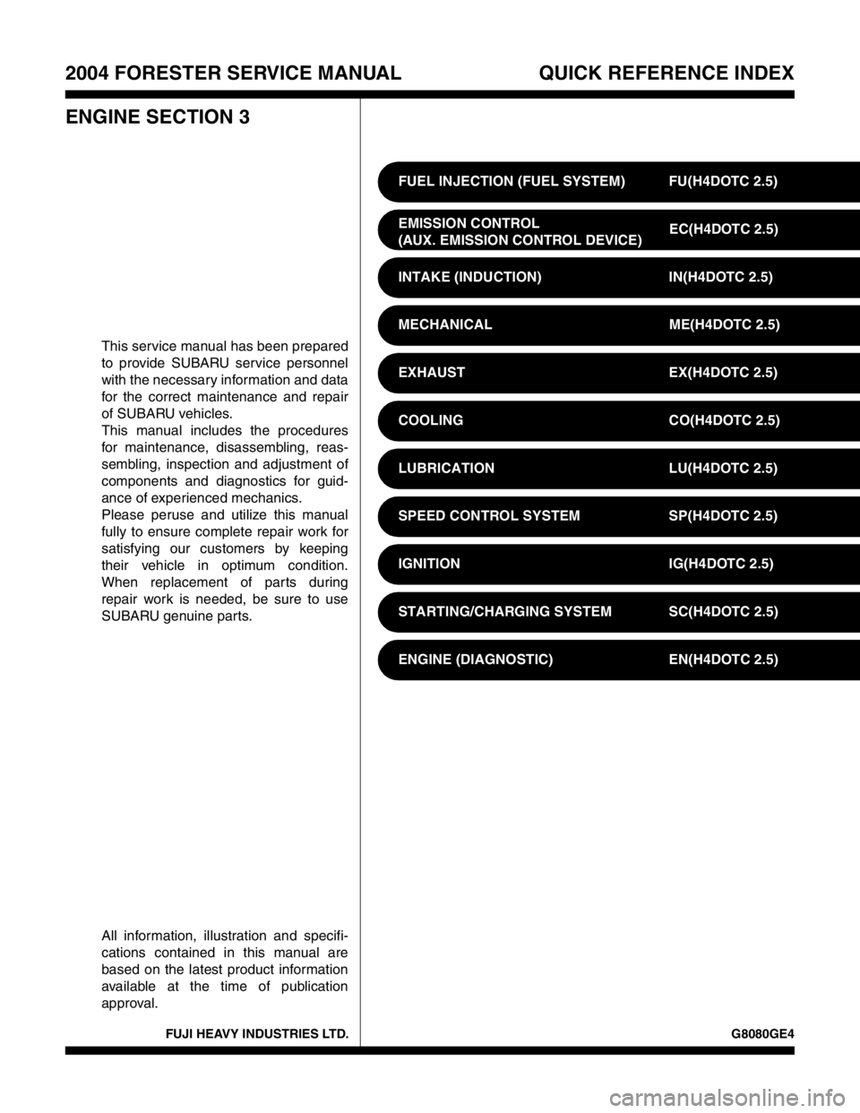
FUJI HEAVY INDUSTRIES LTD. G8080GE4
2004 FORESTER SERVICE MANUAL QUICK REFERENCE INDEX
ENGINE SECTION 3
This service manual has been prepared
to provide SUBARU service personnel
with the necessary information and data
for the correct maintenance and repair
of SUBARU vehicles.
This manual includes the procedures
for maintenance, disassembling, reas-
sembling, inspection and adjustment of
components and diagnostics for guid-
ance of experienced mechanics.
Please peruse and utilize this manual
fully to ensure complete repair work for
satisfying our customers by keeping
their vehicle in optimum condition.
When replacement of parts during
repair work is needed, be sure to use
SUBARU genuine parts.
All information, illustration and specifi-
cations contained in this manual are
based on the latest product information
available at the time of publication
approval.FUEL INJECTION (FUEL SYSTEM) FU(H4DOTC 2.5)
EMISSION CONTROL
(AUX. EMISSION CONTROL DEVICE)EC(H4DOTC 2.5)
INTAKE (INDUCTION) IN(H4DOTC 2.5)
MECHANICAL ME(H4DOTC 2.5)
EXHAUST EX(H4DOTC 2.5)
COOLING CO(H4DOTC 2.5)
LUBRICATION LU(H4DOTC 2.5)
SPEED CONTROL SYSTEM SP(H4DOTC 2.5)
IGNITION IG(H4DOTC 2.5)
STARTING/CHARGING SYSTEM SC(H4DOTC 2.5)
ENGINE (DIAGNOSTIC) EN(H4DOTC 2.5)
Page 2021 of 2870
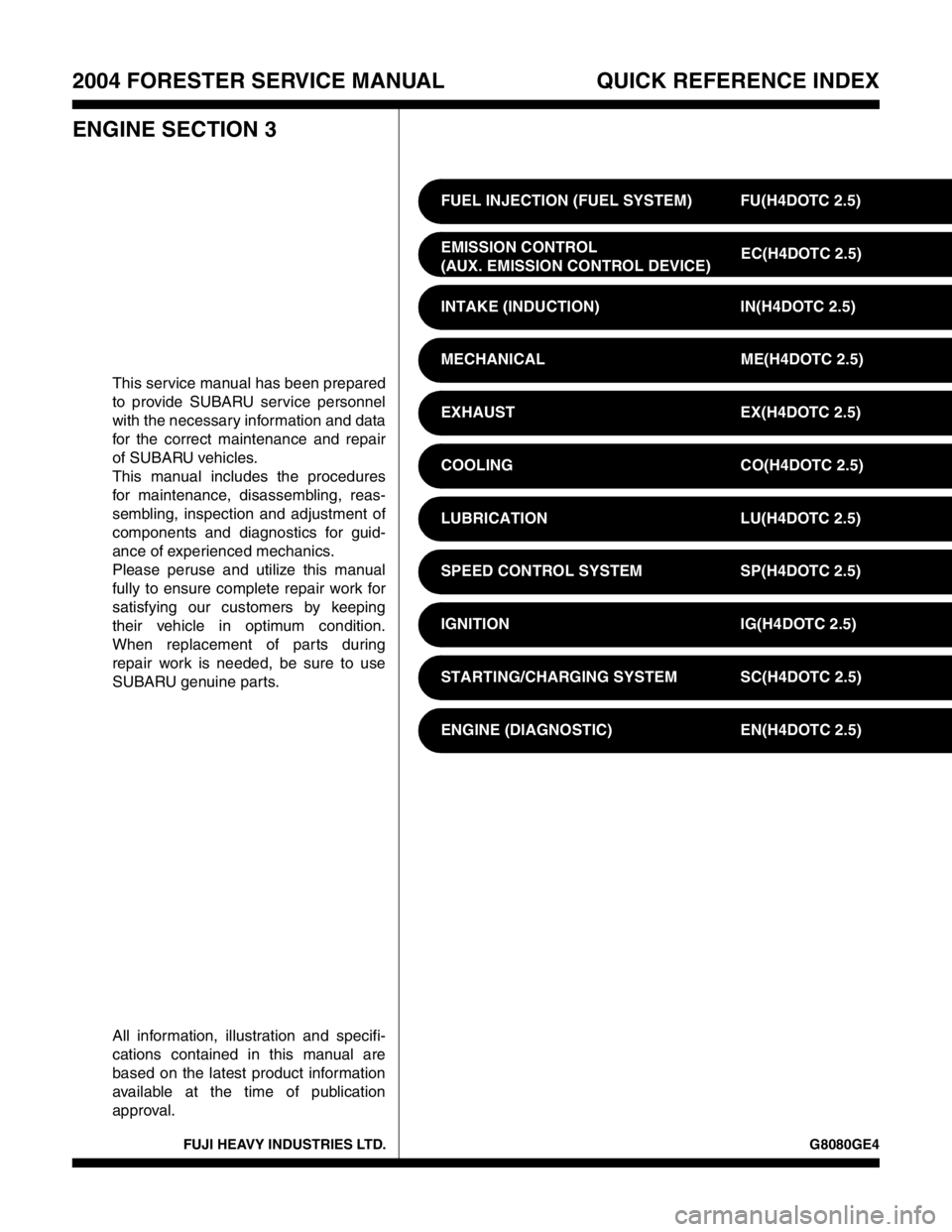
FUJI HEAVY INDUSTRIES LTD. G8080GE4
2004 FORESTER SERVICE MANUAL QUICK REFERENCE INDEX
ENGINE SECTION 3
This service manual has been prepared
to provide SUBARU service personnel
with the necessary information and data
for the correct maintenance and repair
of SUBARU vehicles.
This manual includes the procedures
for maintenance, disassembling, reas-
sembling, inspection and adjustment of
components and diagnostics for guid-
ance of experienced mechanics.
Please peruse and utilize this manual
fully to ensure complete repair work for
satisfying our customers by keeping
their vehicle in optimum condition.
When replacement of parts during
repair work is needed, be sure to use
SUBARU genuine parts.
All information, illustration and specifi-
cations contained in this manual are
based on the latest product information
available at the time of publication
approval.FUEL INJECTION (FUEL SYSTEM) FU(H4DOTC 2.5)
EMISSION CONTROL
(AUX. EMISSION CONTROL DEVICE)EC(H4DOTC 2.5)
INTAKE (INDUCTION) IN(H4DOTC 2.5)
MECHANICAL ME(H4DOTC 2.5)
EXHAUST EX(H4DOTC 2.5)
COOLING CO(H4DOTC 2.5)
LUBRICATION LU(H4DOTC 2.5)
SPEED CONTROL SYSTEM SP(H4DOTC 2.5)
IGNITION IG(H4DOTC 2.5)
STARTING/CHARGING SYSTEM SC(H4DOTC 2.5)
ENGINE (DIAGNOSTIC) EN(H4DOTC 2.5)
Page 2024 of 2870
FUJI HEAVY INDUSTRIES LTD. G8080GE4
2004 FORESTER SERVICE MANUAL QUICK REFERENCE INDEX
ENGINE SECTION 3
This service manual has been prepared
to provide SUBARU service personnel
with the necessary information and data
for the correct maintenance and repair
of SUBARU vehicles.
This manual includes the procedures
for maintenance, disassembling, reas-
sembling, inspection and adjustment of
components and diagnostics for guid-
ance of experienced mechanics.
Please peruse and utilize this manual
fully to ensure complete repair work for
satisfying our customers by keeping
their vehicle in optimum condition.
When replacement of parts during
repair work is needed, be sure to use
SUBARU genuine parts.
All information, illustration and specifi-
cations contained in this manual are
based on the latest product information
available at the time of publication
approval.FUEL INJECTION (FUEL SYSTEM) FU(H4DOTC 2.5)
EMISSION CONTROL
(AUX. EMISSION CONTROL DEVICE)EC(H4DOTC 2.5)
INTAKE (INDUCTION) IN(H4DOTC 2.5)
MECHANICAL ME(H4DOTC 2.5)
EXHAUST EX(H4DOTC 2.5)
COOLING CO(H4DOTC 2.5)
LUBRICATION LU(H4DOTC 2.5)
SPEED CONTROL SYSTEM SP(H4DOTC 2.5)
IGNITION IG(H4DOTC 2.5)
STARTING/CHARGING SYSTEM SC(H4DOTC 2.5)
ENGINE (DIAGNOSTIC) EN(H4DOTC 2.5)
Page 2059 of 2870

EN(H4DOTC 2.5)-35
ENGINE (DIAGNOSTIC)
Inspection Mode
11.Inspection Mode
A: OPERATION
Perform the diagnosis on the “Diagnosis Trouble Codes (DTC) List” below.
Refer to the item of drive cycle when perform the diagnosis not on the “Diagnosis Trouble Codes (DTC) List”
below.
DTC Item On condition
P0031 HO2S Heater Control Circuit Low (Bank 1 Sensor 1) —
P0032 HO2S Heater Control Circuit High (Bank 1 Sensor 1) —
P0037 HO2S Heater Control Circuit Low (Bank 1 Sensor 2) —
P0038 HO2S Heater Control Circuit High (Bank 1 Sensor 2) —
P0102 Mass or Volume Air Flow Circuit Low Input —
P0103 Mass or Volume Air Flow Circuit High Input —
P0107 Manifold Absolute Pressure/Barometric Pressure Circuit Low Input —
P0108 Manifold Absolute Pressure/Barometric Pressure Circuit High Input —
P0112 Intake Air Temperature Circuit Low Input —
P0113 Intake Air Temperature Circuit High Input —
P0117 Engine Coolant Temperature Circuit Low Input —
P0118 Engine Coolant Temperature Circuit High Input —
P0122 Throttle/Pedal Position Sensor/Switch “A” Circuit Low Input —
P0123 Throttle/Pedal Position Sensor/Switch “A” Circuit High Input —
P0131 O
2 Sensor Circuit Low Voltage (Bank 1 Sensor 1)
—
P0132 O
2 Sensor Circuit High Voltage (Bank 1 Sensor 1)
—
P0137 O
2 Sensor Circuit Low Voltage (Bank 1 Sensor 2)
—
P0138 O
2 Sensor Circuit High Voltage (Bank 1 Sensor 2)
—
P0222 Throttle/Pedal Position Sensor/Switch “B” Circuit Low Input —
P0223 Throttle/Pedal Position Sensor/Switch “B” Circuit High Input —
P0230 Fuel Pump Primary Circuit —
P0245 Turbo/Super Charger Wastegate Solenoid “A” Low —
P0327 Knock Sensor 1 Circuit Low Input (Bank 1 or Single Sensor) —
P0328 Knock Sensor 1 Circuit High Input (Bank 1 or Single Sensor) —
P0335 Crankshaft Position Sensor “A” Circuit —
P0340 Camshaft Position Sensor “A” Circuit (Bank 1 or Single Sensor) —
P0345 Camshaft Position Sensor “A” Circuit (Bank 2) —
P0458 Evaporative Emission Control System Purge Control Valve Circuit Low —
P0459 Evaporative Emission Control System Purge Control Valve Circuit High —
P0462 Fuel Level Sensor Circuit Low Input —
P0463 Fuel Level Sensor Circuit High Input —
P0502 Vehicle Speed Sensor Circuit Low Input —
P0503 Vehicle Speed Sensor Intermittent/Erratic/High —
P0512 Starter Request Circuit—
P0513 Incorrect Immobilizer Key —
P0519 Idle Control System Malfunction (Fail-Safe) —
P0545 Exhaust Gas Temperature Sensor Circuit Low-Bank 1 —
P0600 Serial Communication Link —
P0604 Internal Control Module Random Access Memory (RAM) Error —
P0605 Internal Control Module Read Only Memory (ROM) Error —
P0607 Control Module Performance —
P0638 Throttle Actuator Control Range/Performance (Bank 1) —
P0691 Cooling Fan 1 Control Circuit Low —
P0700 Transmission Control System (MIL Request) —
P0851 Neutral Switch Input Circuit Low —
Page 2064 of 2870

EN(H4DOTC 2.5)-40
ENGINE (DIAGNOSTIC)
Drive Cycle
12.Drive Cycle
A: OPERATION
There are three driving patterns on diagnosis. Following trouble can be diagnosed with driving specified pat-
terns. After repair the following trouble, be sure to check that the trouble is cleared correctly by the driving
specified patterns.
1. PREPARATION FOR DRIVE CYCLE
1) Check battery voltage is more than 12 V and fuel remains half [20 — 402 (5.3 — 10.6 US gal, 4.4 — 8.8
Imp gal)].
2) Disconnect the test mode connectors.
NOTE:
Be sure to perform the diagnosis after idling from starting the cooled engine except when the engine coolant
temperature is specified.
2. DRIVE THE VEHICLE 20 MINUTES AT THE SPEED OF 80 KM/H (50 MPH), AND THEN IDLE
THE ENGINE 1 MINUTE.
3. 10 MINUTES IDLING
NOTE:
Drive the vehicle more than 10 km/h (6 MPH) before diagnosis.
DTC Item On condition
P0546 Exhaust Gas Temperature Sensor Circuit High - Bank 1 —
P0692 Cooling Fan 1 Control Circuit High —
DTC Item On condition
P0171 System Too Lean (Bank 1) —
P0172 System Too Rich (Bank 2) —
Page 2091 of 2870

EN(H4DOTC 2.5)-67
ENGINE (DIAGNOSTIC)
List of Diagnostic Trouble Code (DTC)
P0512 Starter Request Circuit
P0513 Incorrect Immobilizer Key
P0519 Idle Control System Malfunction
(Fail-Safe)
Code (DTC).>
P0545 Exhaust Gas Temperature Sensor
Circuit Low-Bank 1
nostic Trouble Code (DTC).>
P0546 Exhaust Gas Temperature Sensor
Circuit High-Bank 1
Trouble Code (DTC).>
P0600 Serial Communication Link
P0604 Internal Control Module Random
Access Memory (RAM) Error
Diagnostic Trouble Code (DTC).>
P0605 Internal Control Module Read
Access Memory (RAM) Error
Diagnostic Trouble Code (DTC).>
P0607 Control Module Performance
P0638 Throttle Actuator Control Range/
Performance (Bank 1)
nostic Trouble Code (DTC).>
P0691 Cooling Fan 1 Control Circuit Low
P0692 Cooling Fan 1 Control Circuit High
P0700 Transmission Control System (MIL
Request)
Code (DTC).>
P0851 Neutral Switch Input Circuit Low
Code (DTC).>
P0852 Neutral Switch Input Circuit High
Code (DTC).>
P1086 Tumble Generated Valve Position
Sensor 2 Circuit Low
tic Trouble Code (DTC).>
P1087 Tumble Generated Valve Position
Sensor 2 Circuit High
tic Trouble Code (DTC).>
P1088 Tumble Generated Valve Position
Sensor 1 Circuit Low
tic Trouble Code (DTC).>
P1089 Tumble Generated Valve Position
Sensor 1 Circuit High
tic Trouble Code (DTC).>
P1090 Tumble Generated Valve System 1
(Valve Open)
Code (DTC).>
P1091 Tumble Generated Valve System 1
(Valve Close)
Code (DTC).> DTC Item NOTE