2004 SUBARU FORESTER airbag off
[x] Cancel search: airbag offPage 230 of 2870

AB-98
AIRBAG SYSTEM (DIAGNOSTIC)
Diagnostic Procedure with Diagnostic Trouble Code (DTC)
Step Check Yes No
1 CHECK LAP SEAT BELT PRETENSIONER.
1) Turn the ignition switch to OFF, disconnect
the battery ground cable, and wait more than
20 seconds.
2) Disconnect the connector (AB25) from the
lap seat belt pretensioner (RH).
3) Connect the connector (1Q) in test harness
Q to (AB25).
4) Connect the airbag resistor to connector
(2Q) in test harness Q.
5) Connect the battery ground cable, and turn
the ignition switch to ON.Is the airbag warning light
turned on normally?Replace the lap
seat belt preten-
sioner (RH).
OUTER SEAT
BELT WITH LAP
SEAT BELT PRE-
TENSIONER,
REMOVAL, Front
Seat Belt.>Go to step 2.
2 CHECK SIDE AIRBAG HARNESS (RH).
1) Turn the ignition switch to OFF, disconnect
the battery ground cable, and wait more than
20 seconds.
2) Disconnect the airbag resistor from the test
harness.
3) Disconnect the connector (AB11) from side
airbag module (RH).
4) Disconnect the connectors (AB20) from
seat belt pretensioner.
5) Disconnect the connector (AB8) from air-
bag control module.
6) Connect the connector (1R) in test harness
R to the connector (AB8).
7) Measure the resistance between connector
(3R) in test harness R and connector (2Q) in
test harness Q.
Connector & terminal
(3R) No. 2 — (2Q) No. 2:
(3R) No. 4 — (2Q) No. 1: Is the resistance less than 10
Ω?Go to step 3.Replace the side
airbag harness
with body harness.
3 CHECK SIDE AIRBAG HARNESS.
Measure the resistance between the connector
(3R) in test harness R and the chassis ground.
Connector & terminal
(3R) No. 2 — (3R) No. 4:
(3R) No. 2 — Chassis ground:
(3R) No. 4 — Chassis ground: Is the resistance more than 1
MΩ?Replace the airbag
control module.
Module.>Replace the side
airbag harness
with body harness.
Page 231 of 2870

AB-99
AIRBAG SYSTEM (DIAGNOSTIC)
Diagnostic Procedure with Diagnostic Trouble Code (DTC)
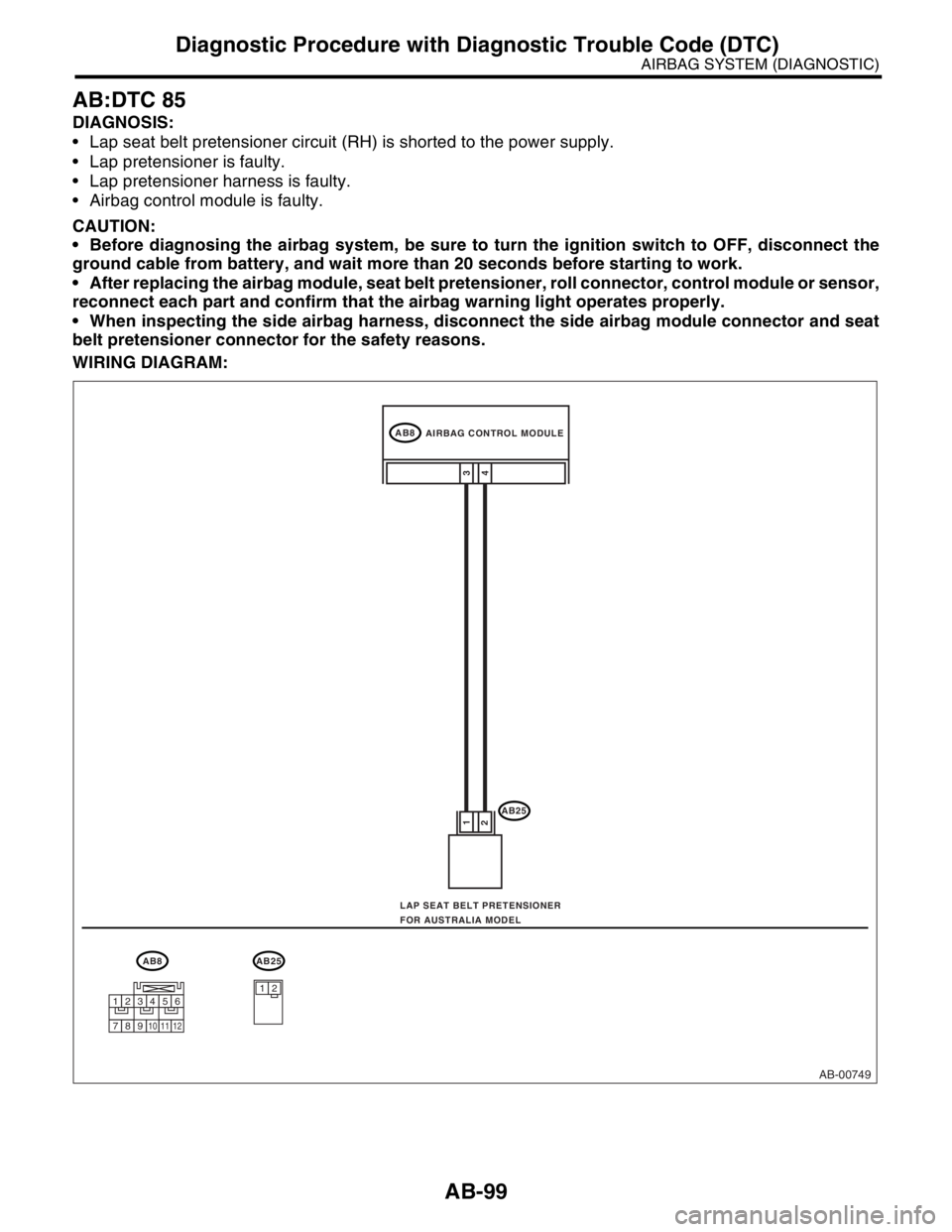
AB:DTC 85
DIAGNOSIS:
Lap seat belt pretensioner circuit (RH) is shorted to the power supply.
Lap pretensioner is faulty.
Lap pretensioner harness is faulty.
Airbag control module is faulty.
CAUTION:
Before diagnosing the airbag system, be sure to turn the ignition switch to OFF, disconnect the
ground cable from battery, and wait more than 20 seconds before starting to work.
After replacing the airbag module, seat belt pretensioner, roll connector, control module or sensor,
reconnect each part and confirm that the airbag warning light operates properly.
When inspecting the side airbag harness, disconnect the side airbag module connector and seat
belt pretensioner connector for the safety reasons.
WIRING DIAGRAM:
AB-00749
AB8
AB25
4 1
23
AB8AB25
12
AIRBAG CONTROL MODULE
LAP SEAT BELT PRETENSIONER
FOR AUSTRALIA MODEL
123456
789101112
Page 232 of 2870

AB-100
AIRBAG SYSTEM (DIAGNOSTIC)
Diagnostic Procedure with Diagnostic Trouble Code (DTC)
Step Check Yes No
1 CHECK LAP SEAT BELT PRETENSIONER.
1) Turn the ignition switch to OFF, disconnect
the battery ground cable, and wait more than
20 seconds.
2) Disconnect the connector (AB25) from the
lap seat belt pretensioner (RH).
3) Connect the connector (1Q) in test harness
Q to (AB25).
4) Connect the airbag resistor to the connec-
tor (2Q) in test harness Q.
5) Connect the battery ground cable and turn
the ignition switch to ON.Is the airbag warning light
turned on normally?Replace the lap
seat belt preten-
sioner (RH).
OUTER SEAT
BELT WITH LAP
SEAT BELT PRE-
TENSIONER,
REMOVAL, Front
Seat Belt.>Go to step 2.
2 CHECK SIDE AIRBAG HARNESS (RH).
1) Turn the ignition switch to OFF, disconnect
the battery ground cable, and wait more than
20 seconds.
2) Disconnect the airbag resistor from the test
harness.
3) Disconnect the connector (AB11) from side
airbag module (RH).
4) Disconnect the connector (AB20) from seat
belt pretensioner.
5) Disconnect the connectors (AB7) and
(AB8) from the airbag control module.
6) Connect the connector (1R) in test harness
R to the connector (AB7).
7) Connect the battery ground cable and turn
the ignition switch to ON.
8) Measure the voltage between connector
(3R) in test harness R and the chassis ground.
Connector & terminal
(3R) No. 2 (+) — Chassis ground (
−):
(3R) No. 4 (+) — Chassis ground (
−): Is the voltage less than 1 V? Replace the airbag
control module.
Module.>Replace the side
airbag harness
with body harness.
Page 238 of 2870

SB-4
SEAT BELT SYSTEM
General Description
B: CAUTION
Before starting, turn the ignition switch to OFF,
disconnect the battery ground cable and wait for 20
seconds or more.
The pretension system has a backup power source.
The pretensioner might deploy if you do not wait for 20
seconds or more before starting work.
Do not drop or apply any impact to the preten-
sioner.
If oil, grease, or water gets on the pretensioner,
wipe it off immediately with a dry cloth.
Do not expose the pretensioner to high tempera-
ture or flame.
Do not allow current to flow through or voltage to
reach the pretensioner. Do not use a circuit tester
to check resistance of the pretensioner.
Do not disassemble or attempt to repair the pre-
tensioner. If it is dented, cracked, or deformed, re-
place it with a new one.
Do not use the airbag or pretensioner parts from
other vehicles. Always replace parts with new
parts.
When handling a seat belt with a deployed pre-
tensioner, wear gloves and goggles. Wash your
hands afterwards.
Do not re-use a seat belt with a deployed preten-
sioner again.
Be sure to deploy pretensioner before disposal.
If the material gets in your eyes or on your skin
during deployment, wash it away with clean water,
and then consult a doctor.
Page 561 of 2870

CC-9
CRUISE CONTROL SYSTEM
Cruise Control Command Switch
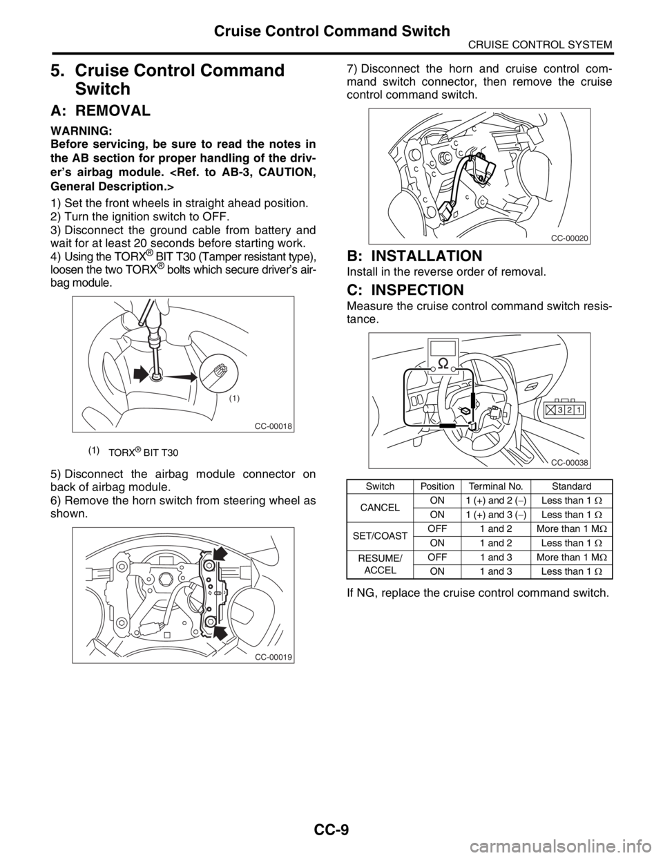
5. Cruise Control Command
Switch
A: REMOVAL
WARNING:
Before servicing, be sure to read the notes in
the AB section for proper handling of the driv-
er’s airbag module.
1) Set the front wheels in straight ahead position.
2) Turn the ignition switch to OFF.
3) Disconnect the ground cable from battery and
wait for at least 20 seconds before starting work.
4) Using the TORX
® BIT T30 (Tamper resistant type),
loosen the two TORX® bolts which secure driver’s air-
bag module.
5) Disconnect the airbag module connector on
back of airbag module.
6) Remove the horn switch from steering wheel as
shown.7) Disconnect the horn and cruise control com-
mand switch connector, then remove the cruise
control command switch.
B: INSTALLATION
Install in the reverse order of removal.
C: INSPECTION
Measure the cruise control command switch resis-
tance.
If NG, replace the cruise control command switch.
(1)
TORX® BIT T30
CC-00018
(1)
CC-00019
Switch Position Terminal No. Standard
CANCELON 1 (+) and 2 (−) Less than 1 Ω
ON 1 (+) and 3 (−) Less than 1 Ω
SET/COASTOFF 1 and 2 More than 1 MΩ
ON 1 and 2 Less than 1 Ω
RESUME/
ACCELOFF 1 and 3 More than 1 MΩ
ON 1 and 3 Less than 1 Ω
CC-00020
CC-00038
1 2 3
Page 645 of 2870

IM-3
IMMOBILIZER (DIAGNOSTIC)
General Description
2. General Description
A: CAUTION
CAUTION:
The airbag system wiring harnesses rout-
ed near the immobilizer control module. All
airbag system wiring harness and connec-
tors are colored yellow. Do not use electrical
test equipment on these circuits.
Be careful not to damage the airbag system
wiring harness when servicing the immobilizer
control module.
While diagnostic items are being checked, do
not operate radios, portable telephones, etc.
which emit electromagnetic waves near or
inside the vehicle.
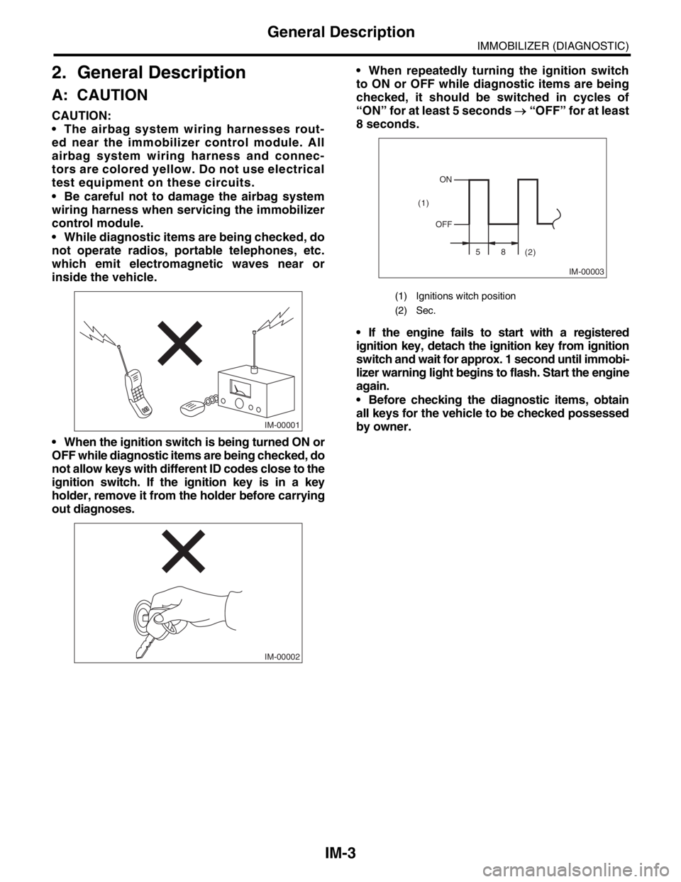
When the ignition switch is being turned ON or
OFF while diagnostic items are being checked, do
not allow keys with different ID codes close to the
ignition switch. If the ignition key is in a key
holder, remove it from the holder before carrying
out diagnoses. When repeatedly turning the ignition switch
to ON or OFF while diagnostic items are being
checked, it should be switched in cycles of
“ON” for at least 5 seconds → “OFF” for at least
8 seconds.
If the engine fails to start with a registered
ignition key, detach the ignition key from ignition
switch and wait for approx. 1 second until immobi-
lizer warning light begins to flash. Start the engine
again.
Before checking the diagnostic items, obtain
all keys for the vehicle to be checked possessed
by owner.
IM-00001
IM-00002
(1) Ignitions witch position
(2) Sec.
IM-00003
ON
OFF
58
(2) (1)
Page 701 of 2870

PC-2
PRECAUTION
Precaution
1. Precaution
A: PRECAUTION
Please clearly understand and adhere to the follow-
ing general precautions. They must be strictly fol-
lowed to avoid minor or serious injury to the person
doing the work or people in the area.
1. ABS
Handle the ABS as a total system. Do not disas-
semble or attempt to repair individual parts. Doing
so could prevent the ABS system from operating
when needed or cause it to operate incorrectly and
result in injury.
2. BRAKE FLUID
If brake fluid gets in your eyes or on your skin, do
the following:
Wash out your eyes and seek immediate medical
attention.
Wash your skin with soap and then rinse thor-
oughly with water.
3. RADIATOR FAN
The radiator fan may rotate without warning, even
when the engine is not on. Do not place your hand,
cloth, tools, or other items near the fan at any time.
4. ROAD TESTS
Always conduct road tests in accordance with traf-
fic rules and regulations to avoid bodily injury and
interrupting traffic.
5. AIRBAG
To prevent bodily injury from unexpected deploy-
ment of airbags and unnecessary maintenance, fol-
low the instructions in this manual when performing
maintenance on airbag components or nearby, and
airbag wiring harnesses or nearby.
To prevent unexpected deployment, perform the
steps below and then wait at least 20 seconds to
discharge electricity before beginning work.
Step 1: Turn the ignition switch OFF.
Step 2: Disconnect the ground cable from bat-
tery.
6. AIRBAG DISPOSAL
To prevent bodily injury from unexpected airbag
deployment, do not dispose airbag modules in the
same way as other refuse. Follow all government
regulations concerning disposal of refuse.
7. AIRBAG MODULE
Adhere to the following when handling and storing
the airbag module to prevent bodily injury from un-
expected deployment:
Do not hold the harnesses or connectors to carry
module.
Do not face the bag in the direction that it opens
towards yourself or other people.
Do not face the bag in the direction that it opens
towards the floor or walls.
8. AIRBAG SPECIAL TOOLS
To prevent unexpected deployment, only use spe-
cial tools.
9. WINDOW
Always wear safety glasses when working around
any glass to prevent glass fragments from damag-
ing your eyes.
10.WINDOW ADHESIVE
Always use the recommended or alternative adhe-
sive when attaching glass to prevent it from coming
loose and falling, resulting in accidents and injury.
Page 1104 of 2870

EN(H4SO)-6
ENGINE (DIAGNOSTIC)
General Description
3. General Description
A: CAUTION
1) Airbag system wiring harness is routed near the
ECM, main relay and fuel pump relay.
CAUTION:
All air bag system wiring harnesses and con-
nectors are yellow. Do not use the electrical
test equipment on these circuits.
Be careful not to damage the Airbag system
wiring harness when servicing the ECM, TCM,
main relay and fuel pump relay.
2) Never connect the battery in reverse polarity.
The ECM will be destroyed immediately.
The fuel injector and other part will be damaged.
3) Do not disconnect the battery terminals while the
engine is running.
A large counter electromotive force will be generat-
ed in the generator, and this voltage may damage
electronic parts such as ECM, etc.
4) Before disconnecting the connectors of each
sensor and the ECM, be sure to turn the ignition
switch to OFF.
5) Poor contact has been identified as a primary
cause of this problem. Measure the voltage or re-
sistance of individual sensor or all electrical control
modules using a tapered pin with a diameter of less
than 0.64 mm (0.025 in). Do not insert the pin more
than 5 mm (0.20 in) into the part.
6) Remove the ECM from the located position after
disconnecting two cables on battery.
Otherwise, the ECM may be damaged.
CAUTION:
When replacing the ECM, be careful not to use
the wrong spec. ECM to avoid any damage on
the fuel injection system.
7) Connectors to each sensor in the engine com-
partment and the harness connectors on the en-
gine side and body side are all designed to be
waterproof. However, it is still necessary to take
care not to allow water to get into the connectors
when washing the vehicle, or when servicing the
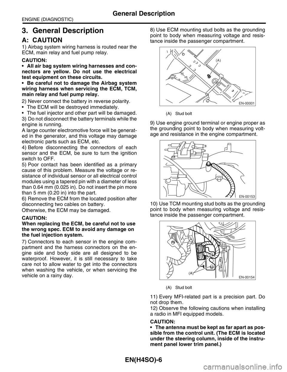
vehicle on a rainy day.8) Use ECM mounting stud bolts as the grounding
point to body when measuring voltage and resis-
tance inside the passenger compartment.
9) Use engine ground terminal or engine proper as
the grounding point to body when measuring volt-
age and resistance in the engine compartment.
10) Use TCM mounting stud bolts as the grounding
point to body when measuring voltage and resis-
tance inside the passenger compartment.
11) Every MFI-related part is a precision part. Do
not drop them.
12) Observe the following cautions when installing
a radio in MFI equipped models.
CAUTION:
The antenna must be kept as far apart as pos-
sible from the control unit. (The ECM is located
under the steering column, inside of the instru-
ment panel lower trim panel.)
(A) Stud bolt
(A) Stud bolt
EN-00001
(A)
EN-00153
EN-00154(A)