2004 NISSAN TERRANO fuel pressure
[x] Cancel search: fuel pressurePage 645 of 1833
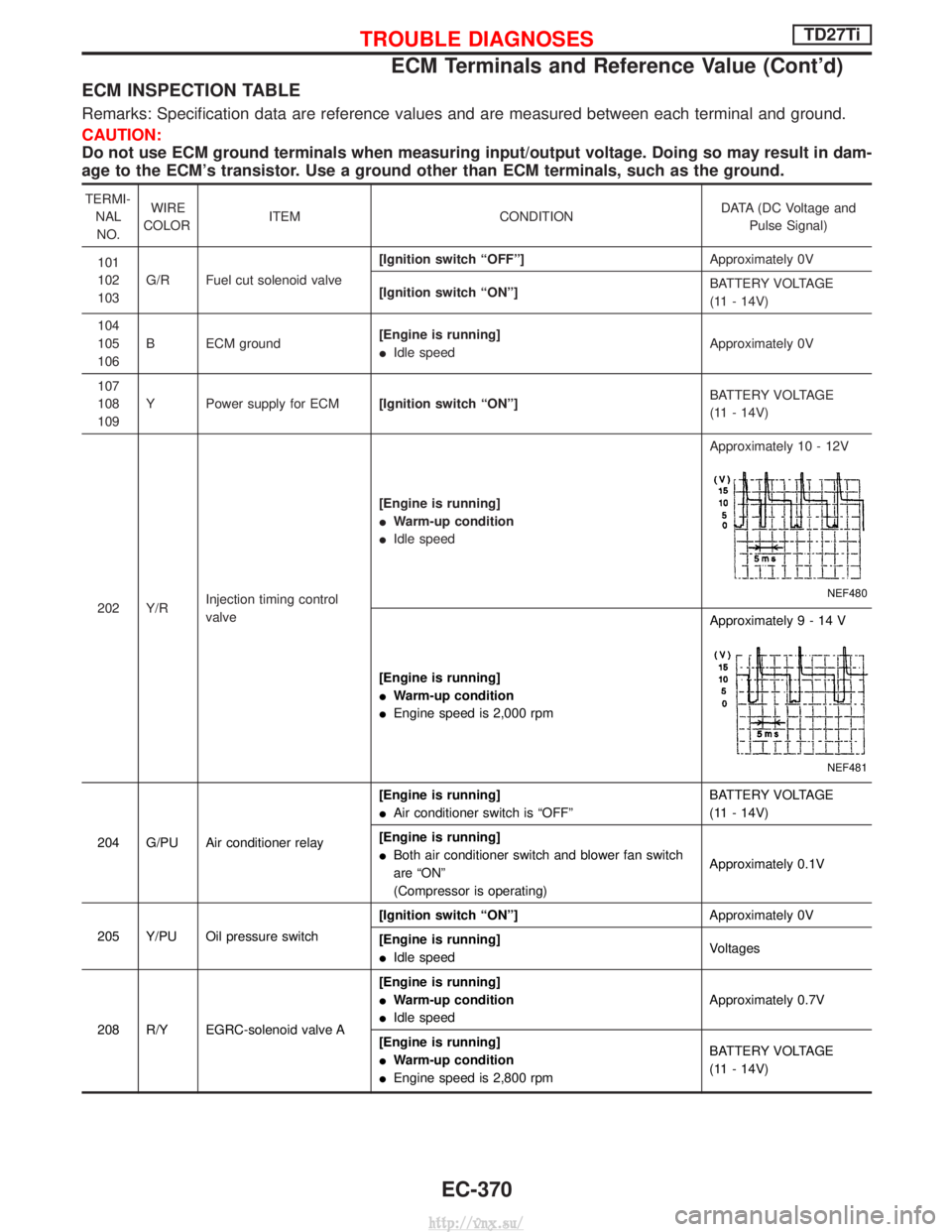
ECM INSPECTION TABLE
Remarks: Specification data are reference values and are measured between each terminal and ground.
CAUTION:
Do not use ECM ground terminals when measuring input/output voltage. Doing so may result in dam-
age to the ECM's transistor. Use a ground other than ECM terminals, such as the ground.
TERMI-NALNO. WIRE
COLOR ITEM CONDITION DATA (DC Voltage and
Pulse Signal)
101
102
103 G/R Fuel cut solenoid valve [Ignition switch ªOFFº]
Approximately 0V
[Ignition switch ªONº] BATTERY VOLTAGE
(11 - 14V)
104
105
106 B ECM ground
[Engine is running]
I
Idle speed Approximately 0V
107
108
109 Y Power supply for ECM
[Ignition switch ªONº] BATTERY VOLTAGE
(11 - 14V)
202 Y/R Injection timing control
valve [Engine is running]
I
Warm-up condition
I Idle speed Approximately 10 - 12V
NEF480
[Engine is running]
I
Warm-up condition
I Engine speed is 2,000 rpm Approximately9-14V
NEF481
204 G/PU Air conditioner relay
[Engine is running]
I
Air conditioner switch is ªOFFº BATTERY VOLTAGE
(11 - 14V)
[Engine is running]
I Both air conditioner switch and blower fan switch
are ªONº
(Compressor is operating) Approximately 0.1V
205 Y/PU Oil pressure switch [Ignition switch ªONº]
Approximately 0V
[Engine is running]
I Idle speed Voltages
208 R/Y EGRC-solenoid valve A [Engine is running]
I
Warm-up condition
I Idle speed Approximately 0.7V
[Engine is running]
I Warm-up condition
I Engine speed is 2,800 rpm BATTERY VOLTAGE
(11 - 14V)
TROUBLE DIAGNOSESTD27Ti
ECM Terminals and Reference Value (Cont'd)
EC-370
http://vnx.su/
Page 678 of 1833

Component Description
INJECTION TIMING CONTROL VALVE
The injection timing control valve is built into the fuel injection
pump. It controls the timer piston to change the fuel injection tim-
ing.
The timing control valve is a solenoid valve located in the line
between high-pressure chamber and low-pressure chamber. It
changes fuel pressure in the high-pressure chamber.
When current flows through the solenoid (the solenoid turns ON),
the timing control valve opens, advancing fuel injection timing.
When current does not flow through it, the timing control valve
closes, retarding injection timing.
The ECM emits an ON-OFF duty signal. The longer the OFF-
duration, the greater the advance angle. The longer the
ON-duration, the greater the retard angle. This means that chang-
ing the ON-OFF duty ratio makes it possible to achieve an optimal
advance angle and accurately control fuel injection timing.
On Board Diagnosis Logic
DTCMalfunction is detected when .... Check Items
(Possible cause)
P0216
0904 I
Injection timing control valve circuit is open or
shorted. I
Harness or connectors
(The injection timing control valve circuit is open or
shorted)
I Injection timing control valve
P1246
0201 I
Injection timing feedback system does not operate
properly. (This system consists essentially of ECM,
injection timing control valve and needle lift sensor.) I
Harness or connectors
[Injection timing control valve, needle lift sensor,
crankshaft position sensor (TDC) circuits]
I Injection timing control valve
I Needle lift sensor
I Crankshaft position sensor (TDC)
I Air in fuel line
DTC P0216 Confirmation Procedure
WITH CONSULT-II
1) Turn ignition switch to ªONº position.
2) Select ªDATA MONITORº mode with CONSULT-II.
3) Wait at least 2 seconds.
WITHOUT CONSULT-II
1) Turn ignition switch to ªONº position.
2) Wait at least 2 seconds.
3) Turn ignition switch to ªLOCKº position, wait at least 5 seconds
and then turn to ªONº position.
4) Perform ªDiagnostic Test Mode IIº (Self-diagnostic results).
SEF638S
DTC P0216 INJ TIMING CONT/V, DTC P1246 F/INJ TIMG F/BTD27Ti
EC-403
http://vnx.su/
Page 751 of 1833

General Specifications
Engine speed
Unit: rpm
EngineTD27Ti
Idle speed A/C: ON 725
845
Maximum engine speed 5,500
Pump numbers
Engine Part numberPump assembly num-
ber
TD27Ti 16700 7F406 A 460 801 135
Pump data is not yet available.
Refer to CALIBRATION STANDARD published
by BOSCH.
Injection Nozzle
INSPECTION AND ADJUSTMENT
Injection nozzle assembly
Unit: kPa (bar, kg/cm2, psi)
Initial injection pressure
New 12,749 - 13,730 (127.5 - 137.3, 130 - 140,
1,849 - 1,991)
Used 12,259 - 12,749 (122.6 - 127.5, 120 - 135,
1,706 - 1,849)
Inspection and Adjustment
Plunger lift mm (in)
at TDC 0.275 0.02
(0.0108) (0.0008)
Idle speed rpm
(ªNº or ªPº position) 725 25
MASS AIR FLOW SENSOR
Supply voltage
V Approximately 5
Output voltage V1.5 - 2.7*
*: Engine is warmed up sufficiently and idling under no-load.
ENGINE COOLANT TEMPERATURE
SENSOR
Temperature ÉC (ÉF) Resistance kW
20 (68) 2.1 - 2.9
50 (122) 0.68 - 1.00
90 (194) 0.236 - 0.260
CONTROL SLEEVE POSITION SENSOR
Resistance [at 25ÉC (77ÉF)] WApproximately 6.1
INJECTION TIMING CONTROL VALVE
Resistance [at 25ÉC (77ÉF)] WApproximately 15
NEEDLE LIFT SENSOR
Resistance [at 25ÉC (77ÉF)] WApproximately 105
CRANKSHAFT POSITION SENSOR (TDC)
Resistance [at 25ÉC (77ÉF)] WApproximately 900
GLOW PLUG
Resistance [at 25ÉC (77ÉF)] W0.5
ACCELERATOR POSITION SENSOR
Throttle valve conditions Resistance kW
[at 25ÉC (77ÉF)]
Completely closed Approximately 1.2
Partially open 1.2 - 1.9
Completely open Approximately 1.9
FUEL TEMPERATURE SENSOR
Temperature ÉC (ÉF)Resistance kW
25 (77) Approximately 1.9
SERVICE DATA AND SPECIFICATIONS (SDS)TD27Ti
EC-476
http://vnx.su/
Page 758 of 1833
WARNING:
When replacing fuel line parts, be sure to observe the following:
IDisplay a ªCAUTION: INFLAMMABLEº sign in workshop.
I Be sure to furnish workshop with a CO
2fire extinguisher service.
I Do not smoke while servicing fuel system. Keep open flames and sparks away from work area.
I Be sure to disconnect battery ground cable before conducting operations.
I Pour drained fuel into an explosion-proof container, then ensure container lid is installed securely.
CAUTION:
I For ECM models, release fuel pressure from fuel line. Refer to EC section (ªFuel Pressure Releaseº,
ªBASIC SERVICE PROCEDUREº).
I Do not disconnect any fuel line unless absolutely necessary.
I Plug hose and pipe openings to prevent entry of dust or dirt.
I Always replace top lid seal and hose clamps with new ones.
I Do not kink or twist hoses and tubes during installation.
I Do not tighten hose clamps excessively because this could cause damage to the hose.
I Ensure fuel check valve is installed in the correct orientation.
I Refer to EC section (ªFUEL CHECK VALVEº, ªEVAPORATIVE EMISSION SYSTEMº).
I After installation, run engine and check for fuel leaks at connections.
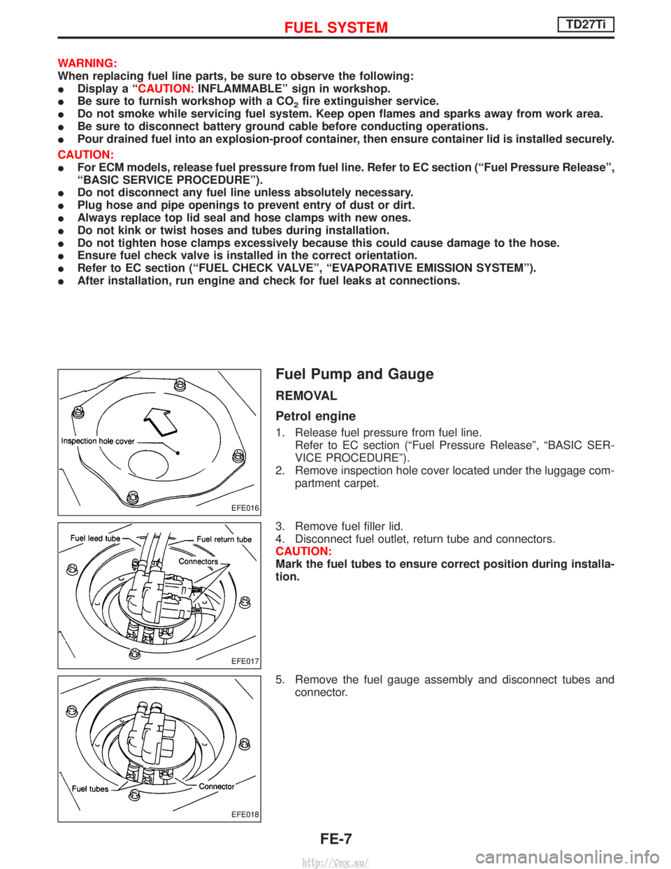
Fuel Pump and Gauge
REMOVAL
Petrol engine
1. Release fuel pressure from fuel line.
Refer to EC section (ªFuel Pressure Releaseº, ªBASIC SER-
VICE PROCEDUREº).
2. Remove inspection hole cover located under the luggage com- partment carpet.
3. Remove fuel filler lid.
4. Disconnect fuel outlet, return tube and connectors.
CAUTION:
Mark the fuel tubes to ensure correct position during installa-
tion.
5. Remove the fuel gauge assembly and disconnect tubes and connector.
EFE016
EFE017
EFE018
FUEL SYSTEMTD27Ti
FE-7
http://vnx.su/
Page 1180 of 1833
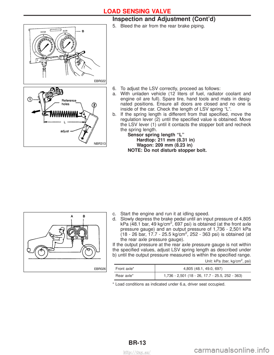
5. Bleed the air from the rear brake piping.
6. To adjust the LSV correctly, proceed as follows:
a. With unladen vehicle (12 liters of fuel, radiator coolant andengine oil are full). Spare tire, hand tools and mats in desig-
nated positions. Ensure all doors are closed and no one is
inside of the car. Check the length of LSV spring ªLº.
b. If the spring length is different from that specified, move the regulation lever (2) until the specified value is obtained. Move
the LSV lever (1) until it contacts the stopper bolt and recheck
the spring length.Sensor spring length ªLº Hardtop: 211 mm (8.31 in)
Wagon: 209 mm (8.23 in)
NOTE: Do not disturb stopper bolt.
c. Start the engine and run it at idling speed.
d. Slowly depress the brake pedal until an input pressure of 4,805 kPa (48.1 bar, 49 kg/cm
2, 697 psi) is obtained (at the front axle
pressure gauge) and an output pressure of 1,736 - 2,501 kPa
(18 - 26 bar, 17.7 - 25.5 kg/cm
2, 252 - 363 psi) is obtained (at
the rear axle pressure gauge).
If the output pressure at the rear axle pressure gauge is not within
the specified values, adjust LSV spring length as described under
b) until the output pressure measured is within the specified range.
Unit: kPa (bar, kg/cm2, psi)
Front axle* 4,805 (48.1, 49.0, 697)
Rear axle* 1,736 - 2,501 (18 - 26, 17.7 - 25.5, 252 - 363)
* Load conditions as indicated under 6.a, driver seat occupied.
EBR022
NBR313
EBR026
LOAD SENSING VALVE
Inspection and Adjustment (Cont'd)
BR-13
http://vnx.su/
Page 1516 of 1833
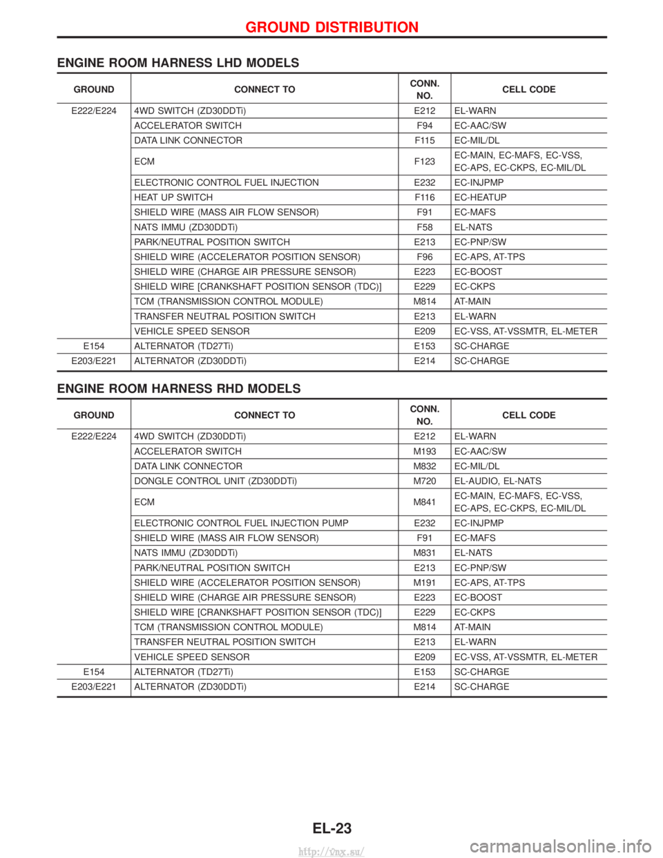
ENGINE ROOM HARNESS LHD MODELS
GROUNDCONNECT TO CONN.
NO. CELL CODE
E222/E224 4WD SWITCH (ZD30DDTi) E212 EL-WARN
ACCELERATOR SWITCH F94 EC-AAC/SW
DATA LINK CONNECTOR F115 EC-MIL/DL
ECM F123EC-MAIN, EC-MAFS, EC-VSS,
EC-APS, EC-CKPS, EC-MIL/DL
ELECTRONIC CONTROL FUEL INJECTION E232 EC-INJPMP
HEAT UP SWITCH F116 EC-HEATUP
SHIELD WIRE (MASS AIR FLOW SENSOR) F91 EC-MAFS
NATS IMMU (ZD30DDTi) F58 EL-NATS
PARK/NEUTRAL POSITION SWITCH E213 EC-PNP/SW
SHIELD WIRE (ACCELERATOR POSITION SENSOR) F96 EC-APS, AT-TPS
SHIELD WIRE (CHARGE AIR PRESSURE SENSOR) E223 EC-BOOST
SHIELD WIRE [CRANKSHAFT POSITION SENSOR (TDC)] E229 EC-CKPS
TCM (TRANSMISSION CONTROL MODULE) M814 AT-MAIN
TRANSFER NEUTRAL POSITION SWITCH E213 EL-WARN
VEHICLE SPEED SENSOR E209 EC-VSS, AT-VSSMTR, EL-METER
E154 ALTERNATOR (TD27Ti) E153 SC-CHARGE
E203/E221 ALTERNATOR (ZD30DDTi) E214 SC-CHARGE
ENGINE ROOM HARNESS RHD MODELS
GROUNDCONNECT TO CONN.
NO. CELL CODE
E222/E224 4WD SWITCH (ZD30DDTi) E212 EL-WARN
ACCELERATOR SWITCH M193 EC-AAC/SW
DATA LINK CONNECTOR M832 EC-MIL/DL
DONGLE CONTROL UNIT (ZD30DDTi) M720 EL-AUDIO, EL-NATS
ECM M841EC-MAIN, EC-MAFS, EC-VSS,
EC-APS, EC-CKPS, EC-MIL/DL
ELECTRONIC CONTROL FUEL INJECTION PUMP E232 EC-INJPMP
SHIELD WIRE (MASS AIR FLOW SENSOR) F91 EC-MAFS
NATS IMMU (ZD30DDTi) M831 EL-NATS
PARK/NEUTRAL POSITION SWITCH E213 EC-PNP/SW
SHIELD WIRE (ACCELERATOR POSITION SENSOR) M191 EC-APS, AT-TPS
SHIELD WIRE (CHARGE AIR PRESSURE SENSOR) E223 EC-BOOST
SHIELD WIRE [CRANKSHAFT POSITION SENSOR (TDC)] E229 EC-CKPS
TCM (TRANSMISSION CONTROL MODULE) M814 AT-MAIN
TRANSFER NEUTRAL POSITION SWITCH E213 EL-WARN
VEHICLE SPEED SENSOR E209 EC-VSS, AT-VSSMTR, EL-METER
E154 ALTERNATOR (TD27Ti) E153 SC-CHARGE
E203/E221 ALTERNATOR (ZD30DDTi) E214 SC-CHARGE
GROUND DISTRIBUTION
EL-23
http://vnx.su/
Page 1540 of 1833
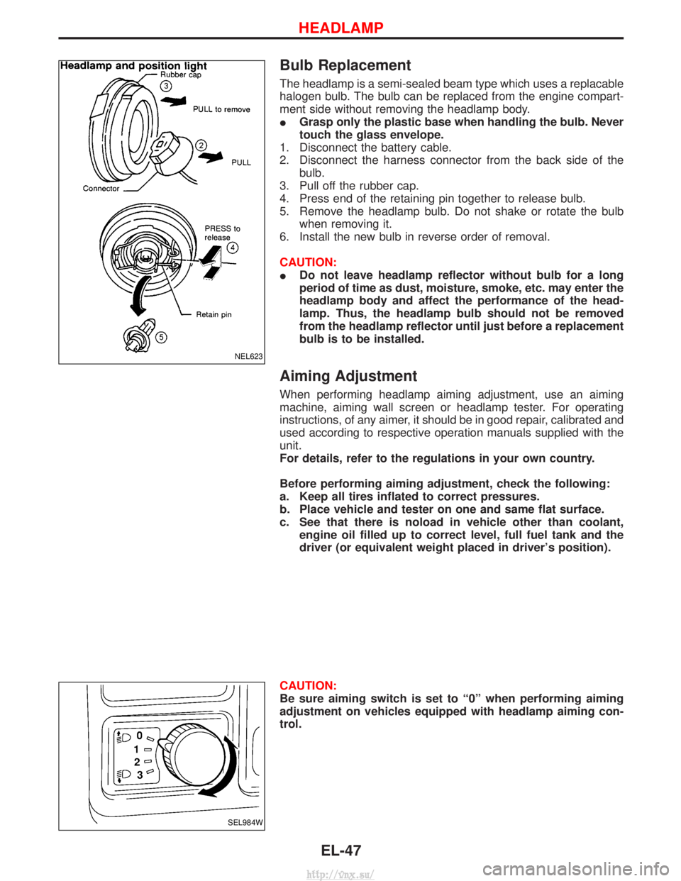
Bulb Replacement
The headlamp is a semi-sealed beam type which uses a replacable
halogen bulb. The bulb can be replaced from the engine compart-
ment side without removing the headlamp body.
IGrasp only the plastic base when handling the bulb. Never
touch the glass envelope.
1. Disconnect the battery cable.
2. Disconnect the harness connector from the back side of the bulb.
3. Pull off the rubber cap.
4. Press end of the retaining pin together to release bulb.
5. Remove the headlamp bulb. Do not shake or rotate the bulb when removing it.
6. Install the new bulb in reverse order of removal.
CAUTION:
I Do not leave headlamp reflector without bulb for a long
period of time as dust, moisture, smoke, etc. may enter the
headlamp body and affect the performance of the head-
lamp. Thus, the headlamp bulb should not be removed
from the headlamp reflector until just before a replacement
bulb is to be installed.
Aiming Adjustment
When performing headlamp aiming adjustment, use an aiming
machine, aiming wall screen or headlamp tester. For operating
instructions, of any aimer, it should be in good repair, calibrated and
used according to respective operation manuals supplied with the
unit.
For details, refer to the regulations in your own country.
Before performing aiming adjustment, check the following:
a. Keep all tires inflated to correct pressures.
b. Place vehicle and tester on one and same flat surface.
c. See that there is noload in vehicle other than coolant,
engine oil filled up to correct level, full fuel tank and the
driver (or equivalent weight placed in driver's position).
CAUTION:
Be sure aiming switch is set to ª0º when performing aiming
adjustment on vehicles equipped with headlamp aiming con-
trol.
NEL623
SEL984W
HEADLAMP
EL-47
http://vnx.su/
Page 1550 of 1833
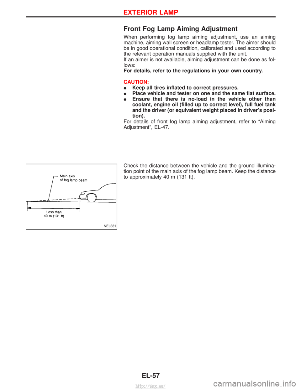
Front Fog Lamp Aiming Adjustment
When performing fog lamp aiming adjustment, use an aiming
machine, aiming wall screen or headlamp tester. The aimer should
be in good operational condition, calibrated and used according to
the relevant operation manuals supplied with the unit.
If an aimer is not available, aiming adjustment can be done as fol-
lows:
For details, refer to the regulations in your own country.
CAUTION:
IKeep all tires inflated to correct pressures.
I Place vehicle and tester on one and the same flat surface.
I Ensure that there is no-load in the vehicle other than
coolant, engine oil (filled up to correct level), full fuel tank
and the driver (or equivalent weight placed in driver's posi-
tion).
For details of front fog lamp aiming adjustment, refer to ªAiming
Adjustmentº, EL-47.
Check the distance between the vehicle and the ground illumina-
tion point of the main axis of the fog lamp beam. Keep the distance
to approximately 40 m (131 ft).
NEL331
EXTERIOR LAMP
EL-57
http://vnx.su/