2004 NISSAN TERRANO fuel pressure
[x] Cancel search: fuel pressurePage 66 of 1833
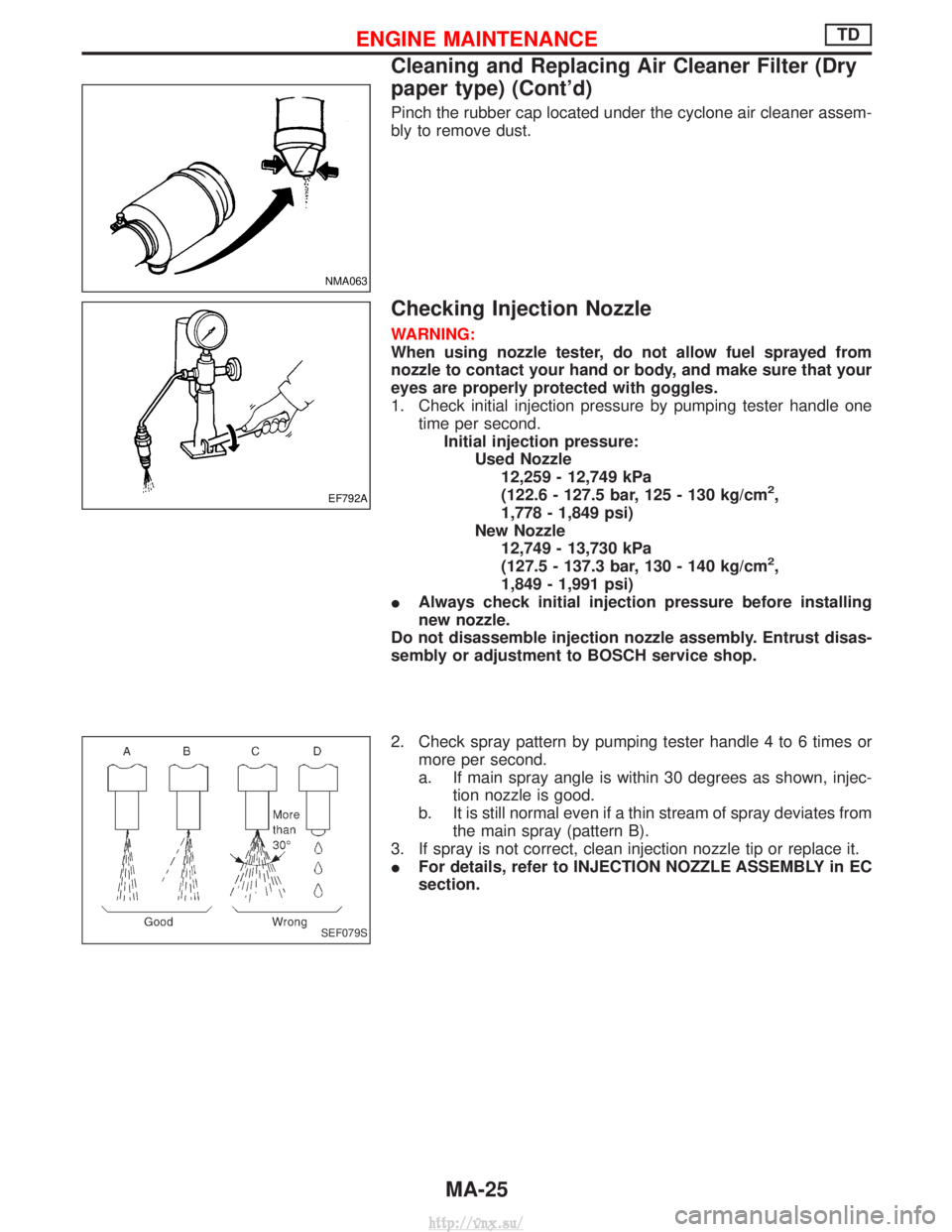
Pinch the rubber cap located under the cyclone air cleaner assem-
bly to remove dust.
Checking Injection Nozzle
WARNING:
When using nozzle tester, do not allow fuel sprayed from
nozzle to contact your hand or body, and make sure that your
eyes are properly protected with goggles.
1. Check initial injection pressure by pumping tester handle onetime per second.Initial injection pressure: Used Nozzle12,259 - 12,749 kPa
(122.6 - 127.5 bar, 125 - 130 kg/cm
2,
1,778 - 1,849 psi)
New Nozzle 12,749 - 13,730 kPa
(127.5 - 137.3 bar, 130 - 140 kg/cm
2,
1,849 - 1,991 psi)
I Always check initial injection pressure before installing
new nozzle.
Do not disassemble injection nozzle assembly. Entrust disas-
sembly or adjustment to BOSCH service shop.
2. Check spray pattern by pumping tester handle 4 to 6 times or more per second.
a. If main spray angle is within 30 degrees as shown, injec- tion nozzle is good.
b. It is still normal even if a thin stream of spray deviates from the main spray (pattern B).
3. If spray is not correct, clean injection nozzle tip or replace it.
I For details, refer to INJECTION NOZZLE ASSEMBLY in EC
section.
NMA063
EF792A
SEF079S
ENGINE MAINTENANCETD
Cleaning and Replacing Air Cleaner Filter (Dry
paper type) (Cont'd)
MA-25
http://vnx.su/
Page 74 of 1833

CHECKING RADIATOR CAP
Apply pressure to radiator cap (side with pressure valve) with cap
tester to see if it is satisfactory.Radiator cap relief pressure:108 - 128 kPa
(1.08 - 1.28 bar, 1.1 - 1.3 kg/cm
2, 16 - 18 psi)
Pull the negative-pressure valve to open it. Check that it closes
completely when released.
CHECKING COOLING SYSTEM FOR LEAKS
Apply pressure to the cooling system with cap tester to check for
leakage. Testing pressure:157 kPa (1.57 bar, 1.6 kg/cm
2, 23 psi)
CAUTION:
Use of higher pressure than the specified value may cause
damage to radiator.
Checking and Replacing Fuel Filter and
Draining Water
Be careful not to spill fuel in engine compartment. Place a rag
to absorb fuel.
CHECKING FUEL FILTER
Check fuel filter for fuel leakage, damage and other abnormal
signs.
REPLACING FUEL FILTER
1. Disconnect harness connector and drain fuel.
2. Remove fuel filter using band-type filter wrench.
3. Remove fuel filter and fuel filter sensor.
CAUTION:
Remove fuel filter without spilling fuel. If spilt, wipe off imme-
diately. Be specially careful not to spill fuel on engine mount
insulator.
SLC613
SMA871B
JMA110D
DMA011
SMA111D
ENGINE MAINTENANCEZD
Checking Cooling System (Cont'd)
MA-33
http://vnx.su/
Page 101 of 1833
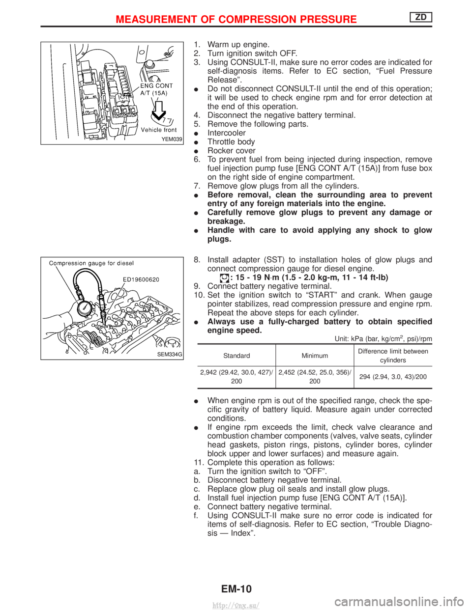
1. Warm up engine.
2. Turn ignition switch OFF.
3. Using CONSULT-II, make sure no error codes are indicated forself-diagnosis items. Refer to EC section, ªFuel Pressure
Releaseº.
I Do not disconnect CONSULT-II until the end of this operation;
it will be used to check engine rpm and for error detection at
the end of this operation.
4. Disconnect the negative battery terminal.
5. Remove the following parts.
I Intercooler
I Throttle body
I Rocker cover
6. To prevent fuel from being injected during inspection, remove fuel injection pump fuse [ENG CONT A/T (15A)] from fuse box
on the right side of engine compartment.
7. Remove glow plugs from all the cylinders.
I Before removal, clean the surrounding area to prevent
entry of any foreign materials into the engine.
I Carefully remove glow plugs to prevent any damage or
breakage.
I Handle with care to avoid applying any shock to glow
plugs.
8. Install adapter (SST) to installation holes of glow plugs and connect compression gauge for diesel engine.
:15-19N ×m (1.5 - 2.0 kg-m, 11 - 14 ft-lb)
9. Connect battery negative terminal.
10. Set the ignition switch to ªSTARTº and crank. When gauge pointer stabilizes, read compression pressure and engine rpm.
Repeat the above steps for each cylinder.
I Always use a fully-charged battery to obtain specified
engine speed.
Unit: kPa (bar, kg/cm2, psi)/rpm
Standard MinimumDifference limit between
cylinders
2,942 (29.42, 30.0, 427)/ 200 2,452 (24.52, 25.0, 356)/
200 294 (2.94, 3.0, 43)/200
I
When engine rpm is out of the specified range, check the spe-
cific gravity of battery liquid. Measure again under corrected
conditions.
I If engine rpm exceeds the limit, check valve clearance and
combustion chamber components (valves, valve seats, cylinder
head gaskets, piston rings, pistons, cylinder bores, cylinder
block upper and lower surfaces) and measure again.
11. Complete this operation as follows:
a. Turn the ignition switch to ªOFFº.
b. Disconnect battery negative terminal.
c. Replace glow plug oil seals and install glow plugs.
d. Install fuel injection pump fuse [ENG CONT A/T (15A)].
e. Connect battery negative terminal.
f. Using CONSULT-II make sure no error code is indicated for items of self-diagnosis. Refer to EC section, ªTrouble Diagno-
sis Ð Indexº.
YEM039
SEM334G
MEASUREMENT OF COMPRESSION PRESSUREZD
EM-10
http://vnx.su/
Page 155 of 1833

Engine room (Left)
3. Remove air duct and air cleaner case.
4. Disconnect vacuum hose to the vehicle on the engine.
5. Disconnect harness connectors from alternator and air com-pressor.
6. Remove alternator.
7. After removing refrigerant, remove pipes of air compressor and inlet/outlet.
8. Disconnect heating hose, install blank cap to hose to prevent coolant from leaking.
9. Remove heating pipe.
10. Remove heat insulator.
11. Remove catalytic converter.
Engine room (Right)
12. Remove power steering reservoir tank from bracket, and fix it to the vehicle with a rope.
CAUTION:
Keep the reservoir tank level when fixing to prevent oil leak.
13. Remove fuel feed and return hoses.
CAUTION:
Install blank caps immediately to avoid fuel leakage.
14. Remove all harness connectors on the engine, and move har- nesses to the side of the vehicle.
Vehicle underfloor
15. Remove starter motor.
16. Detach A/T oil cooler pipes from oil pan. (A/T model)
17. Remove rear propeller shaft.
18. Remove mounting bolts to secure the engine to transmission.
1) Remove torque converter installation bolt. (A/T model)
2) Lift transmission bottom with transmission jack, and removerear mount members from the vehicle.
3) Lower transmission with the jack, and remove upper mounting bolts securing the engine to transmission.
4) Lift transmission with the jack, and reinstall rear mount mem- bers to the vehicle.
5) Position the jack to the front side of transmission.
6) Remove remaining mounting bolts securing the engine to trans- mission.
Removal operation
19. Remove air conditioner high pressure pipes at the rear of theengine room.
I This is due to some inconvenience in the rear slinger installa-
tion.
20. Install the engine slingers (standard service part) to front-left and rear-right.
:25-28N ×m (2.5 - 2.9 kg-m, 18 - 20 ft-lb)
WARNING:
For engines without engine slingers, attach proper slingers
and bolts described in the PARTS CATALOG.
FEM082
ENGINE REMOVALZD
Removal (Cont'd)
EM-64
http://vnx.su/
Page 159 of 1833
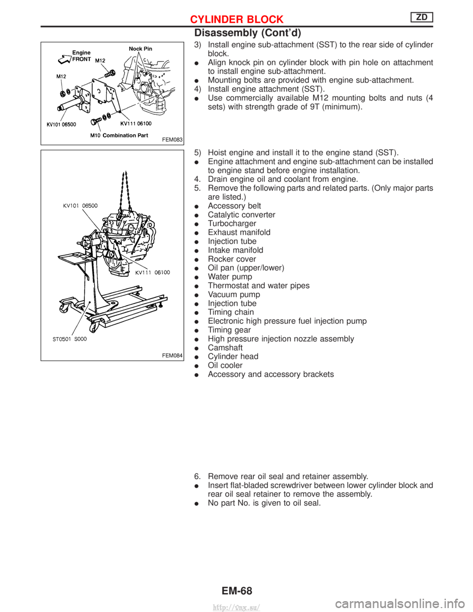
3) Install engine sub-attachment (SST) to the rear side of cylinderblock.
I Align knock pin on cylinder block with pin hole on attachment
to install engine sub-attachment.
I Mounting bolts are provided with engine sub-attachment.
4) Install engine attachment (SST).
I Use commercially available M12 mounting bolts and nuts (4
sets) with strength grade of 9T (minimum).
5) Hoist engine and install it to the engine stand (SST).
I Engine attachment and engine sub-attachment can be installed
to engine stand before engine installation.
4. Drain engine oil and coolant from engine.
5. Remove the following parts and related parts. (Only major parts are listed.)
I Accessory belt
I Catalytic converter
I Turbocharger
I Exhaust manifold
I Injection tube
I Intake manifold
I Rocker cover
I Oil pan (upper/lower)
I Water pump
I Thermostat and water pipes
I Vacuum pump
I Injection tube
I Timing chain
I Electronic high pressure fuel injection pump
I Timing gear
I High pressure injection nozzle assembly
I Camshaft
I Cylinder head
I Oil cooler
I Accessory and accessory brackets
6. Remove rear oil seal and retainer assembly.
I Insert flat-bladed screwdriver between lower cylinder block and
rear oil seal retainer to remove the assembly.
I No part No. is given to oil seal.
FEM083
FEM084
CYLINDER BLOCKZD
Disassembly (Cont'd)
EM-68
http://vnx.su/
Page 278 of 1833
CONSULT-II Reference Value in Data Monitor
Mode ........................................................................\
198
ECM Terminals and Reference Value .....................198
On Board Diagnosis Logic.......................................198
DTC Confirmation Procedure ..................................199
Wiring Diagram ........................................................200
Diagnostic Procedure ..............................................202
DTC 0802 ECM 10.......................................................205 Description ...............................................................205
On Board Diagnosis Logic.......................................205
DTC Confirmation Procedure ..................................205
Diagnostic Procedure ..............................................206
DTC 0804 ECM 11 .......................................................207
Description ...............................................................207
On Board Diagnosis Logic.......................................207
DTC Confirmation Procedure ..................................207
Diagnostic Procedure ..............................................208
DTC 0807 ECM 14.......................................................209 Description ...............................................................209
ECM Terminals and Reference Value .....................209
On Board Diagnosis Logic.......................................209
DTC Confirmation Procedure ..................................209
Wiring Diagram ........................................................210
Diagnostic Procedure .............................................. 211
DTC 0902 ECM RLY ....................................................214
ECM Terminals and Reference Value .....................214
On Board Diagnosis Logic.......................................214
DTC Confirmation Procedure ..................................214
Wiring Diagram ........................................................215
Diagnostic Procedure ..............................................216
DTC 0903 ECM 15.......................................................218 Description ...............................................................218
On Board Diagnosis Logic.......................................218
DTC Confirmation Procedure ..................................218
Diagnostic Procedure ..............................................219
DTC 0905 TURBO PRESSURE ..................................220
Component Description ...........................................220
ECM Terminals and Reference Value .....................220
On Board Diagnosis Logic.......................................220
DTC Confirmation Procedure ..................................221
Wiring Diagram ........................................................222
Diagnostic Procedure ..............................................224
DTC 1003 EGR VOLUME CONT/V .............................227
Description ...............................................................227
CONSULT-II Reference Value in Data Monitor
Mode ........................................................................\
228
ECM Terminals and Reference Value .....................228
On Board Diagnosis Logic.......................................228
DTC Confirmation Procedure ..................................229
Wiring Diagram ........................................................230
Diagnostic Procedure ..............................................232
DTC 1004 FUEL CUT SYSTEM1 ................................237Description ...............................................................237
CONSULT-II Reference Value in Data Monitor
Mode ........................................................................\
238
ECM Terminals and Reference Value .....................238
On Board Diagnosis Logic.......................................238
DTC Confirmation Procedure ..................................239
Wiring Diagram ........................................................240
Diagnostic Procedure ..............................................242
GLOW CONTROL SYSTEM .......................................244
Description ...............................................................244
ECM Terminals and Reference Value .....................245
Wiring Diagram ........................................................246
Diagnostic Procedure ..............................................247
START SIGNAL ...........................................................253
Wiring Diagram ........................................................253
Diagnostic Procedure ..............................................254
PARK/NEUTRAL POSITION (PNP) SWITCH .............256
Description ...............................................................256
CONSULT-II Reference Value in Data Monitor
Mode ........................................................................\
256
ECM Terminals and Reference Value .....................256
Wiring Diagram ........................................................257
Diagnostic Procedure ..............................................258
HEAT UP SWITCH ......................................................265
Component Description ...........................................265
CONSULT-II Reference Value in Data Monitor
Mode ........................................................................\
265
ECM Terminals and Reference Value .....................265
Wiring Diagram ........................................................266
Diagnostic Procedure ..............................................267
SWIRL CONTROL VALVE CONTROL SOLENOID
VA LV E ........................................................................\
..271
Description ...............................................................271
CONSULT-II Reference Value in Data Monitor
Mode ........................................................................\
272
ECM Terminals and Reference Value .....................272
Wiring Diagram ........................................................273
Diagnostic Procedure ..............................................274
INTAKE AIR CONTROL VALVE CONTROL
SOLENOID VALVE ......................................................281
Description ...............................................................281
Operation .................................................................281
ECM Terminals and Reference Value .....................281
Wiring Diagram ........................................................282
Diagnostic Procedure ..............................................283
VARIABLE NOZZLE TURBOCHARGER
CONTROL SOLENOID VALVE ...................................289
Description ...............................................................289
CONSULT-II Reference Value in Data Monitor
Mode ........................................................................\
289
ECM Terminals and Reference Value .....................290
Wiring Diagram ........................................................291
CONTENTS(Cont'd)
EC-3
http://vnx.su/
Page 279 of 1833
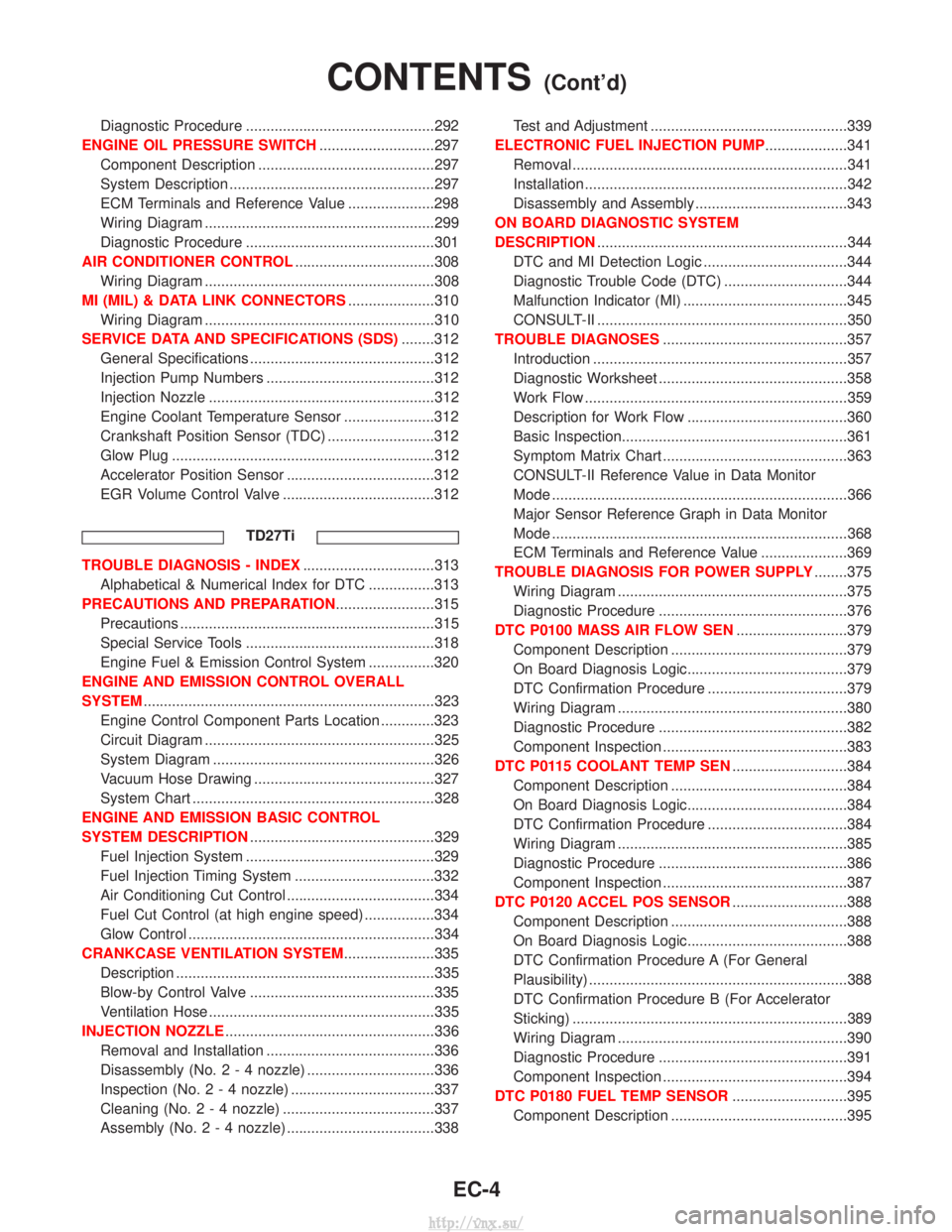
Diagnostic Procedure ..............................................292
ENGINE OIL PRESSURE SWITCH ............................297
Component Description ...........................................297
System Description ..................................................297
ECM Terminals and Reference Value .....................298
Wiring Diagram ........................................................299
Diagnostic Procedure ..............................................301
AIR CONDITIONER CONTROL ..................................308
Wiring Diagram ........................................................308
MI (MIL) & DATA LINK CONNECTORS .....................310
Wiring Diagram ........................................................310
SERVICE DATA AND SPECIFICATIONS (SDS) ........312
General Specifications .............................................312
Injection Pump Numbers .........................................312
Injection Nozzle .......................................................312
Engine Coolant Temperature Sensor ......................312
Crankshaft Position Sensor (TDC) ..........................312
Glow Plug ................................................................312
Accelerator Position Sensor ....................................312
EGR Volume Control Valve .....................................312
TD27Ti
TROUBLE DIAGNOSIS - INDEX ................................313
Alphabetical & Numerical Index for DTC ................313
PRECAUTIONS AND PREPARATION ........................315
Precautions ..............................................................315
Special Service Tools ..............................................318
Engine Fuel & Emission Control System ................320
ENGINE AND EMISSION CONTROL OVERALL
SYSTEM .......................................................................323
Engine Control Component Parts Location .............323
Circuit Diagram ........................................................325
System Diagram ......................................................326
Vacuum Hose Drawing ............................................327
System Chart ...........................................................328
ENGINE AND EMISSION BASIC CONTROL
SYSTEM DESCRIPTION .............................................329
Fuel Injection System ..............................................329
Fuel Injection Timing System ..................................332
Air Conditioning Cut Control ....................................334
Fuel Cut Control (at high engine speed) .................334
Glow Control ............................................................334
CRANKCASE VENTILATION SYSTEM ......................335
Description ...............................................................335
Blow-by Control Valve .............................................335
Ventilation Hose .......................................................335
INJECTION NOZZLE ...................................................336
Removal and Installation .........................................336
Disassembly (No.2-4 nozzle) ...............................336
Inspection (No.2-4 nozzle) ...................................337
Cleaning (No.2-4 nozzle) .....................................337
Assembly (No.2-4 nozzle) ....................................338 Test and Adjustment ................................................339
ELECTRONIC FUEL INJECTION PUMP ....................341
Removal ...................................................................341
Installation ................................................................342
Disassembly and Assembly .....................................343
ON BOARD DIAGNOSTIC SYSTEM
DESCRIPTION .............................................................344
DTC and MI Detection Logic ...................................344
Diagnostic Trouble Code (DTC) ..............................344
Malfunction Indicator (MI) ........................................345
CONSULT-II .............................................................350
TROUBLE DIAGNOSES .............................................357
Introduction ..............................................................357
Diagnostic Worksheet ..............................................358
Work Flow ................................................................359
Description for Work Flow .......................................360
Basic Inspection.......................................................361
Symptom Matrix Chart .............................................363
CONSULT-II Reference Value in Data Monitor
Mode ........................................................................\
366
Major Sensor Reference Graph in Data Monitor
Mode ........................................................................\
368
ECM Terminals and Reference Value .....................369
TROUBLE DIAGNOSIS FOR POWER SUPPLY ........375
Wiring Diagram ........................................................375
Diagnostic Procedure ..............................................376
DTC P0100 MASS AIR FLOW SEN ...........................379
Component Description ...........................................379
On Board Diagnosis Logic.......................................379
DTC Confirmation Procedure ..................................379
Wiring Diagram ........................................................380
Diagnostic Procedure ..............................................382
Component Inspection .............................................383
DTC P0115 COOLANT TEMP SEN ............................384
Component Description ...........................................384
On Board Diagnosis Logic.......................................384
DTC Confirmation Procedure ..................................384
Wiring Diagram ........................................................385
Diagnostic Procedure ..............................................386
Component Inspection .............................................387
DTC P0120 ACCEL POS SENSOR ............................388
Component Description ...........................................388
On Board Diagnosis Logic.......................................388
DTC Confirmation Procedure A (For General
Plausibility) ...............................................................388
DTC Confirmation Procedure B (For Accelerator
Sticking) ...................................................................389
Wiring Diagram ........................................................390
Diagnostic Procedure ..............................................391
Component Inspection .............................................394
DTC P0180 FUEL TEMP SENSOR ............................395
Component Description ...........................................395
CONTENTS(Cont'd)
EC-4
http://vnx.su/
Page 282 of 1833
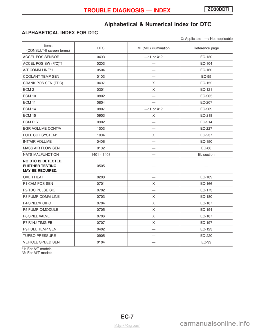
Alphabetical & Numerical Index for DTC
ALPHABETICAL INDEX FOR DTC
X: Applicable Ð: Not applicable
Items
(CONSULT-II screen terms) DTC MI (MIL) illumination Reference page
ACCEL POS SENSOR 0403 Ð*1 or X*2 EC-130
ACCEL POS SW (F/C)*1 0203 Ð EC-104
A/T COMM LINE*1 0504 Ð EC-160
COOLANT TEMP SEN 0103 Ð EC-95
CRANK POS SEN (TDC) 0407 X EC-152
ECM 2 0301 X EC-121
ECM 10 0802 Ð EC-205
ECM 11 0804 Ð EC-207
ECM 14 0807 Ð*1 or X*2 EC-209
ECM 15 0903 X EC-218
ECM RLY 0902 Ð EC-214
EGR VOLUME CONT/V 1003 Ð EC-227
FUEL CUT SYSTEM1 1004 X EC-237
INT/AIR VOLUME 0406 Ð EC-150
MASS AIR FLOW SEN 0102 Ð EC-88
NATS MALFUNCTION 1401 - 1408 Ð EL section
NO DTC IS DETECTED.
FURTHER TESTING
MAY BE REQUIRED. 0505 Ð Ð
OVER HEAT 0208 Ð EC-109
P1×CAM POS SEN 0701XEC-166
P2×TDC PULSE SIG 0702ÐEC-173
P3×PUMP COMM LINE 0703XEC-180
P4×SPILL/V CIRC 0704XEC-187
P5×PUMP C/MODULE 0705XEC-194
P6×SPILL VALVE 0706XEC-187
P7×F/INJ TIMG FB 0707XEC-197
P9×FUEL TEMP SEN 0402ÐEC-123
TURBO PRESSURE 0905ÐEC-220
VEHICLE SPEED SEN 0104ÐEC-99
*1: For A/T models
*2: For M/T models
TROUBLE DIAGNOSIS Ð INDEXZD30DDTi
EC-7
http://vnx.su/