Page 1180 of 1833
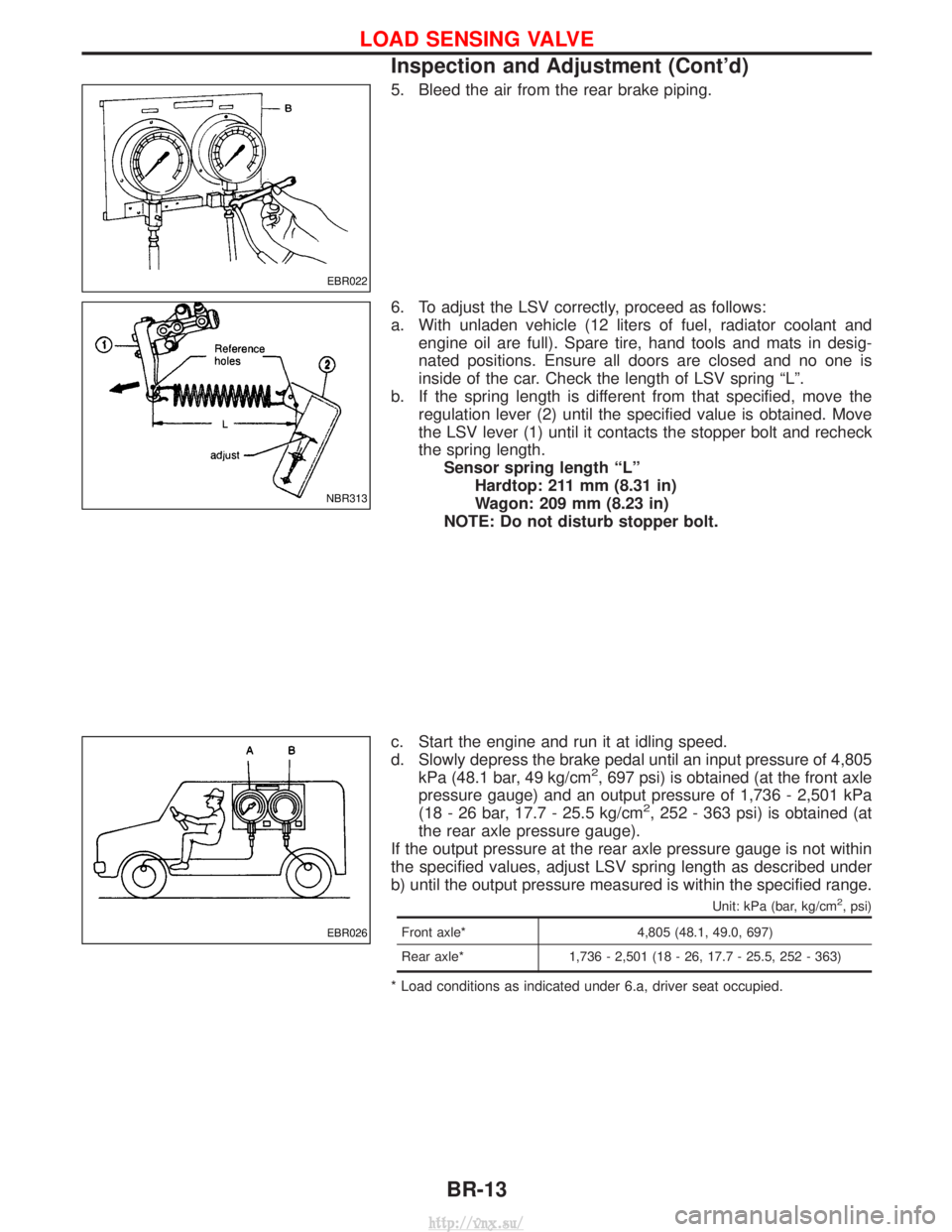
5. Bleed the air from the rear brake piping.
6. To adjust the LSV correctly, proceed as follows:
a. With unladen vehicle (12 liters of fuel, radiator coolant andengine oil are full). Spare tire, hand tools and mats in desig-
nated positions. Ensure all doors are closed and no one is
inside of the car. Check the length of LSV spring ªLº.
b. If the spring length is different from that specified, move the regulation lever (2) until the specified value is obtained. Move
the LSV lever (1) until it contacts the stopper bolt and recheck
the spring length.Sensor spring length ªLº Hardtop: 211 mm (8.31 in)
Wagon: 209 mm (8.23 in)
NOTE: Do not disturb stopper bolt.
c. Start the engine and run it at idling speed.
d. Slowly depress the brake pedal until an input pressure of 4,805 kPa (48.1 bar, 49 kg/cm
2, 697 psi) is obtained (at the front axle
pressure gauge) and an output pressure of 1,736 - 2,501 kPa
(18 - 26 bar, 17.7 - 25.5 kg/cm
2, 252 - 363 psi) is obtained (at
the rear axle pressure gauge).
If the output pressure at the rear axle pressure gauge is not within
the specified values, adjust LSV spring length as described under
b) until the output pressure measured is within the specified range.
Unit: kPa (bar, kg/cm2, psi)
Front axle* 4,805 (48.1, 49.0, 697)
Rear axle* 1,736 - 2,501 (18 - 26, 17.7 - 25.5, 252 - 363)
* Load conditions as indicated under 6.a, driver seat occupied.
EBR022
NBR313
EBR026
LOAD SENSING VALVE
Inspection and Adjustment (Cont'd)
BR-13
http://vnx.su/
Page 1185 of 1833
Removal and Installation
Inspection
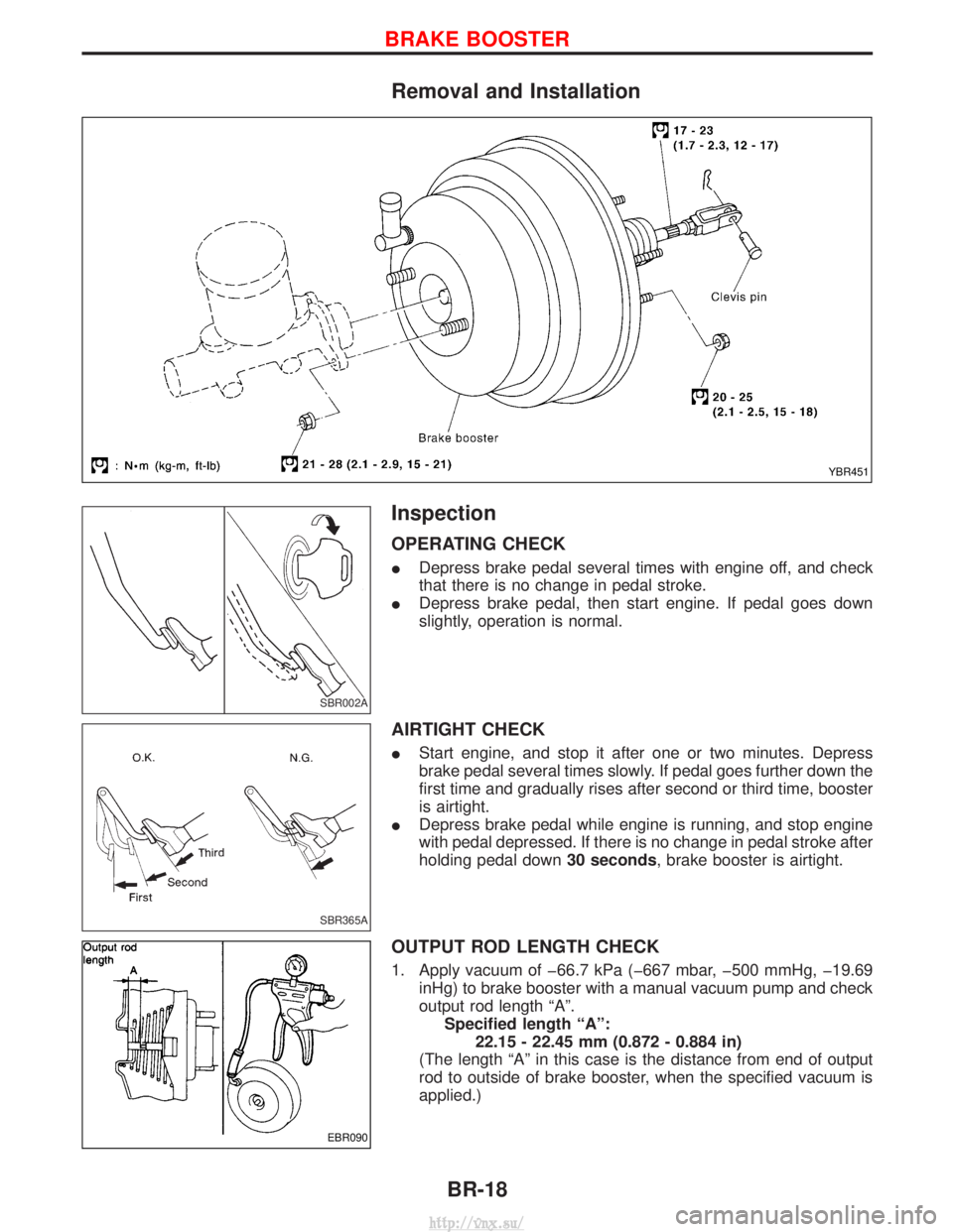
OPERATING CHECK
IDepress brake pedal several times with engine off, and check
that there is no change in pedal stroke.
I Depress brake pedal, then start engine. If pedal goes down
slightly, operation is normal.
AIRTIGHT CHECK
IStart engine, and stop it after one or two minutes. Depress
brake pedal several times slowly. If pedal goes further down the
first time and gradually rises after second or third time, booster
is airtight.
I Depress brake pedal while engine is running, and stop engine
with pedal depressed. If there is no change in pedal stroke after
holding pedal down 30 seconds, brake booster is airtight.
OUTPUT ROD LENGTH CHECK
1. Apply vacuum of þ66.7 kPa (þ667 mbar, þ500 mmHg, þ19.69
inHg) to brake booster with a manual vacuum pump and check
output rod length ªAº.Specified length ªAº: 22.15 - 22.45 mm (0.872 - 0.884 in)
(The length ªAº in this case is the distance from end of output
rod to outside of brake booster, when the specified vacuum is
applied.)
YBR451
SBR002A
SBR365A
EBR090
BRAKE BOOSTER
BR-18
http://vnx.su/
Page 1205 of 1833
Purpose
The Anti-lock Brake System (ABS) with an integrated Electronic Brake force Distribution (EBD) system con-
sists of electronic and hydraulic components. It allows you to control the braking force so that wheel lock can
be avoided during braking.
The advantages of ABS with EBD
1) Better tracking performance through improved steering wheel control.
2) Improved maneuverability and safer vehicle control.
3) Improved vehicle stability by preventing flat spins.
4) Shorter stopping distance and optimal utilisation of the rear brakes under many different circumstances.
Operation
IABS with EBD has self-test capabilities. The ABS warning lamp is illuminated for 1 second each time the
ignition switch is turned ªONº. After the engine is started, the ABS warning lamp turns off. An ABS self-test
is performed the first time the vehicle reaches 6 km/h (4 MPH) to ensure the system is operational. A
mechanical noise may be heard as the ABS performs this self-test and is a normal part of the self-test
feature. If a malfunction is detected during this check, the ABS warning lamp will stay on.
During the self-test, it also performs a EBD check when it detects a failure the ABS warning light will go
on simultaneously with the brake warning light and an audible sound will sound constantly.
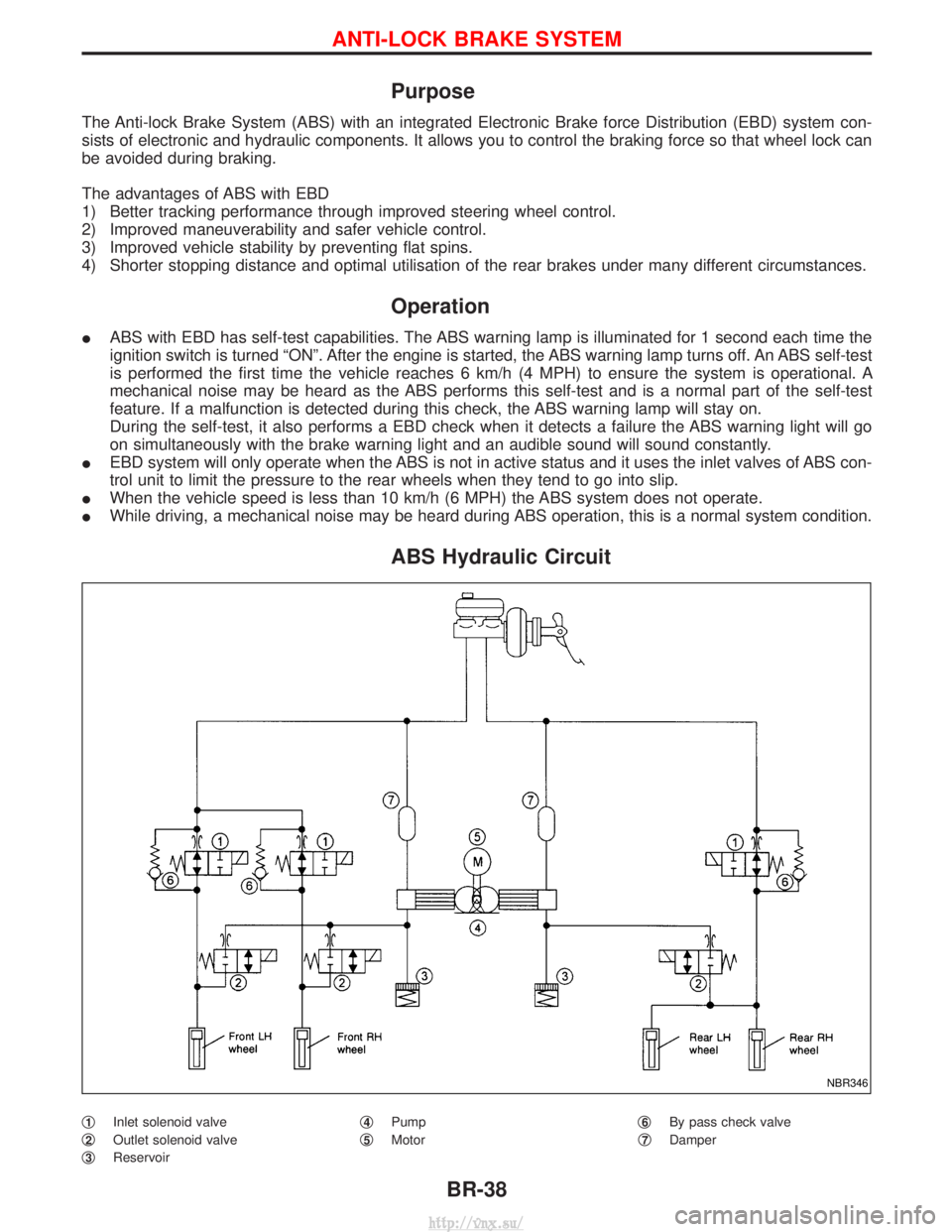
I EBD system will only operate when the ABS is not in active status and it uses the inlet valves of ABS con-
trol unit to limit the pressure to the rear wheels when they tend to go into slip.
I When the vehicle speed is less than 10 km/h (6 MPH) the ABS system does not operate.
I While driving, a mechanical noise may be heard during ABS operation, this is a normal system condition.
ABS Hydraulic Circuit
q1Inlet solenoid valve
q
2Outlet solenoid valve
q
3Reservoir q
4Pump
q
5Motor q
6By pass check valve
q
7Damper
NBR346
ANTI-LOCK BRAKE SYSTEM
BR-38
http://vnx.su/
Page 1227 of 1833
CONSULT-II Inspection Procedure
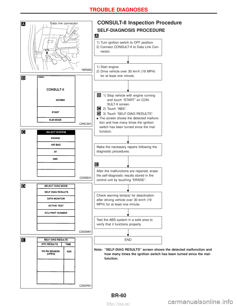
SELF-DIAGNOSIS PROCEDURE
1) Turn ignition switch to OFF position.
2) Connect CONSULT-II to Data Link Con- nector.
1) Start engine.
2) Drive vehicle over 30 km/h (19 MPH) for at least one minute.
1) Stop vehicle with engine runningand touch ªSTARTº on CON-
SULT-II screen.
2) Touch ªABSº.
3) Touch ªSELF-DIAG RESULTSº.
I The screen shows the detected malfunc-
tion and how many times the ignition
switch has been turned since the mal-
function.
Make the necessary repairs following the
diagnostic procedures.
After the malfunctions are repaired, erase
the self-diagnostic results stored in the
control unit by touching ªERASEº.
Check warning lamp(s) for deactivation
after driving vehicle over 30 km/h (19
MPH) for at least one minute.
Test the ABS system in a safe area to
verify that it functions properly.
END
Note: ªSELF-DIAG RESULTSº screen shows the detected malfunction and
how many times the ignition switch has been turned since the mal-
function.
YBR265
C2NCS01
C2SSE01
C2SDM01
C2SDR01
H
H
H
H
H
H
H
TROUBLE DIAGNOSES
BR-60
http://vnx.su/
Page 1232 of 1833
ACTIVE TEST MODE
TEST ITEMCONDITION JUDGEMENT
FR RH SOLENOID
FR LH SOLENOID
RR SOLENOID Engine is running.Brake fluid pressure control operation
IN SOL OUT SOL
UP (Increase):
KEEP (Hold):
DOWN (Decrease): OFF
ON
ON OFF
OFF
ON
ABS MOTOR ABS actuator motor
ON: Motor runs (ABS motor relay ON)
OFF: Motor stops (ABS motor relay OFF)
G-SWITCH Ignition switch is ON or
engine is running.Check G-switch circuit
OFF: G-switch OFF
ON: G-switch ON
Note: Active test will automatically stop ten seconds after the test starts. (LIMIT SIGNAL monitor shows
ON.)
TROUBLE DIAGNOSES
CONSULT-II Inspection Procedure (Cont'd)
BR-65
http://vnx.su/
Page 1248 of 1833
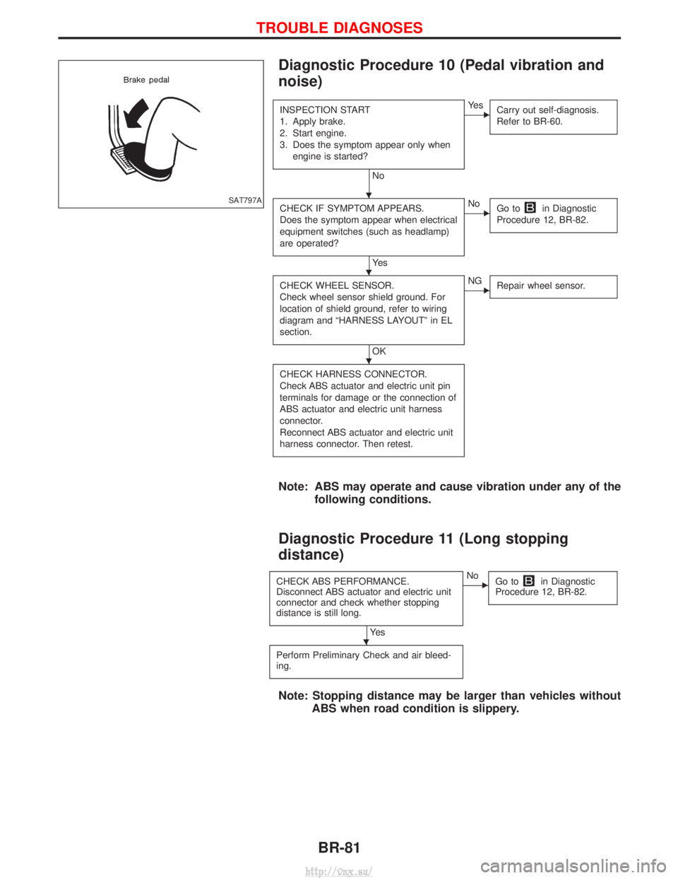
Diagnostic Procedure 10 (Pedal vibration and
noise)
INSPECTION START
1. Apply brake.
2. Start engine.
3. Does the symptom appear only whenengine is started?
No
EYe s Carry out self-diagnosis.
Refer to BR-60.
CHECK IF SYMPTOM APPEARS.
Does the symptom appear when electrical
equipment switches (such as headlamp)
are operated?
Ye s
ENoGo toin Diagnostic
Procedure 12, BR-82.
CHECK WHEEL SENSOR.
Check wheel sensor shield ground. For
location of shield ground, refer to wiring
diagram and ªHARNESS LAYOUTº in EL
section.
OK
ENG Repair wheel sensor.
CHECK HARNESS CONNECTOR.
Check ABS actuator and electric unit pin
terminals for damage or the connection of
ABS actuator and electric unit harness
connector.
Reconnect ABS actuator and electric unit
harness connector. Then retest.
Note: ABS may operate and cause vibration under any of the
following conditions.
Diagnostic Procedure 11 (Long stopping
distance)
CHECK ABS PERFORMANCE.
Disconnect ABS actuator and electric unit
connector and check whether stopping
distance is still long.
Ye s
ENoGo toin Diagnostic
Procedure 12, BR-82.
Perform Preliminary Check and air bleed-
ing.
Note: Stopping distance may be larger than vehicles without ABS when road condition is slippery.
SAT797AH
H
H
H
TROUBLE DIAGNOSES
BR-81
http://vnx.su/
Page 1258 of 1833
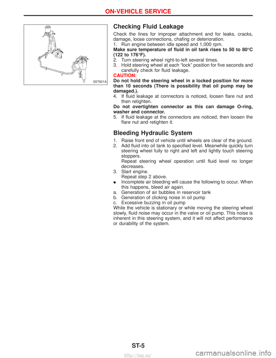
Checking Fluid Leakage
Check the lines for improper attachment and for leaks, cracks,
damage, loose connections, chafing or deterioration.
1. Run engine between idle speed and 1,000 rpm.
Make sure temperature of fluid in oil tank rises to 50 to 80ÉC
(122 to 176ÉF).
2. Turn steering wheel right-to-left several times.
3. Hold steering wheel at each ªlockº position for five seconds andcarefully check for fluid leakage.
CAUTION:
Do not hold the steering wheel in a locked position for more
than 10 seconds (There is possibility that oil pump may be
damaged.).
4. If fluid leakage at connectors is noticed, loosen flare nut and then retighten.
Do not overtighten connector as this can damage O-ring,
washer and connector.
5. If fluid leakage at the connectors are noticed, then loosen the flare nut and retighten it.
Bleeding Hydraulic System
1. Raise front end of vehicle until wheels are clear of the ground.
2. Add fluid into oil tank to specified level. Meanwhile quickly turnsteering wheel fully to right and left and lightly touch steering
stoppers.
Repeat steering wheel operation until fluid level no longer
decreases.
3. Start engine. Repeat step 2 above.
I Incomplete air bleeding will cause the following to occur. When
this happens, bleed air again.
a. Generation of air bubbles in reservoir tank
b. Generation of clicking noise in oil pump
c. Excessive buzzing in oil pump
While the vehicle is stationary or while moving the steering wheel
slowly, fluid noise may occur in the valve or oil pump. This noise is
inherent in this steering system, and it will not affect performance
or durability of the system.
SST621A
ON-VEHICLE SERVICE
ST-5
http://vnx.su/
Page 1404 of 1833
Control Operation
FAN CONTROL DIAL
This DIAL turns the fan ON and OFF, and controls fan speed.
AIR CONTROL DIAL
This DIAL allows outlet air to flow.
TEMPERATURE CONTROL DIAL
This DIAL allows the temperature of the outlet air to be adjusted.
AIR RECIRCULATION SWITCH
OFF position:
Outside air is drawn into the passenger compartment.
ON position (Indicator light ON):
Interior air is recirculated inside the vehicle.
AIR CONDITIONER SWITCH
Start the engine, turn the fan control dial to the desired (1 to 4) position and press the air conditioner switch
to turn ON the air conditioner. The indicator light will come on when the air conditioner is ON. To stop the air
conditioner, push the switch again to return it to the original position.
The air conditioner cooling function operates only when the engine is running.
NHA331
DESCRIPTION Ð Overall System
HA-7
http://vnx.su/