2004 NISSAN TERRANO stop start
[x] Cancel search: stop startPage 28 of 1833
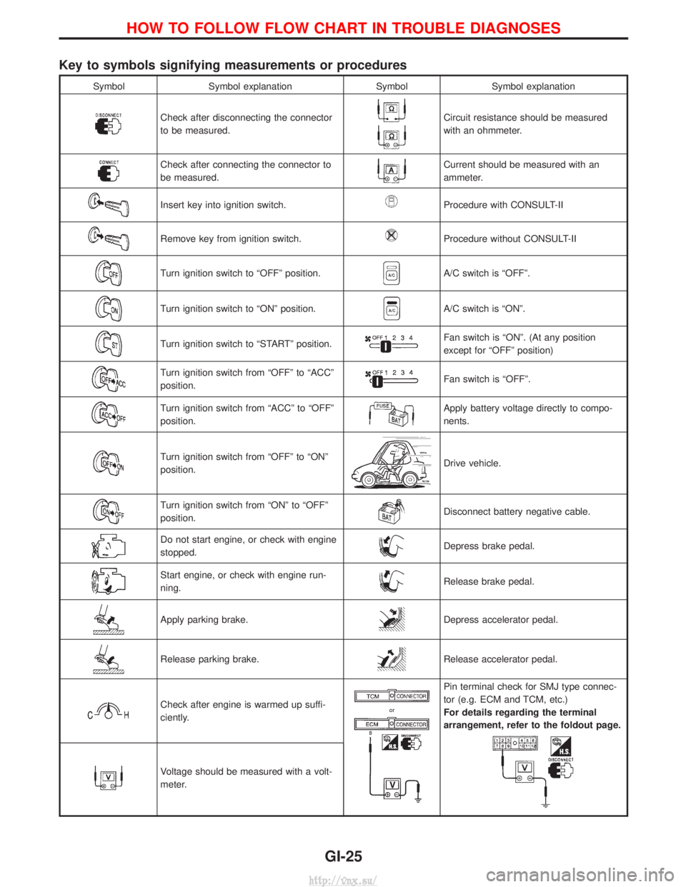
Key to symbols signifying measurements or procedures
SymbolSymbol explanation SymbolSymbol explanation
Check after disconnecting the connector
to be measured.Circuit resistance should be measured
with an ohmmeter.
Check after connecting the connector to
be measured.Current should be measured with an
ammeter.
Insert key into ignition switch.Procedure with CONSULT-II
Remove key from ignition switch.Procedure without CONSULT-II
Turn ignition switch to ªOFFº position.A/C switch is ªOFFº.
Turn ignition switch to ªONº position.A/C switch is ªONº.
Turn ignition switch to ªSTARTº position.Fan switch is ªONº. (At any position
except for ªOFFº position)
Turn ignition switch from ªOFFº to ªACCº
position.Fan switch is ªOFFº.
Turn ignition switch from ªACCº to ªOFFº
position.Apply battery voltage directly to compo-
nents.
Turn ignition switch from ªOFFº to ªONº
position.Drive vehicle.
Turn ignition switch from ªONº to ªOFFº
position.Disconnect battery negative cable.
Do not start engine, or check with engine
stopped.Depress brake pedal.
Start engine, or check with engine run-
ning.Release brake pedal.
Apply parking brake.Depress accelerator pedal.
Release parking brake.Release accelerator pedal.
Check after engine is warmed up suffi-
ciently.
Pin terminal check for SMJ type connec-
tor (e.g. ECM and TCM, etc.)
For details regarding the terminal
arrangement, refer to the foldout page.
Voltage should be measured with a volt-
meter.
HOW TO FOLLOW FLOW CHART IN TROUBLE DIAGNOSES
GI-25
http://vnx.su/
Page 62 of 1833
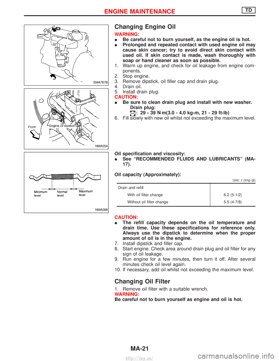
Changing Engine Oil
WARNING:
IBe careful not to burn yourself, as the engine oil is hot.
I Prolonged and repeated contact with used engine oil may
cause skin cancer; try to avoid direct skin contact with
used oil. If skin contact is made, wash thoroughly with
soap or hand cleaner as soon as possible.
1. Warm up engine, and check for oil leakage from engine com- ponents.
2. Stop engine.
3. Remove dipstick, oil filler cap and drain plug.
4. Drain oil.
5. Install drain plug.
CAUTION:
I Be sure to clean drain plug and install with new washer.
Drain plug:
: 29-39N ×m(3.0 - 4.0 kg-m, 21 - 29 ft-lb)
6. Fill slowly with new oil whilst not exceeding the maximum level.
Oil specification and viscosity:
I See ªRECOMMENDED FLUIDS AND LUBRICANTSº (MA-
17).
Oil capacity (Approximately):
Unit: (Imp qt)
Drain and refill
With oil filter change 6.2 (5-1/2)
Without oil filter change 5.5 (4-7/8)
CAUTION:
IThe refill capacity depends on the oil temperature and
drain time. Use these specifications for reference only.
Always use the dipstick to determine when the proper
amount of oil is in the engine.
7. Install dipstick and filler cap.
8. Start engine. Check area around drain plug and oil filter for any sign of oil leakage.
9. Run engine for a few minutes, then turn it off. After several minutes check oil level again.
10. If necessary, add oil whilst not exceeding the maximum level.
Changing Oil Filter
1. Remove oil filter with a suitable wrench.
WARNING:
Be careful not to burn yourself as engine and oil is hot.
SMA787B
NMA054
NMA068
ENGINE MAINTENANCETD
MA-21
http://vnx.su/
Page 70 of 1833

Removal
WATER PUMP, ALTERNATOR AND AIR CONDITIONER
BELT
1. Remove radiator shroud.
2. Contract and hold the auto tensioner using the following proce-dure.
a. Securely hold the 19 mm (0.75 in) hexagonal portion A of auto tensioner with a closed wrench.
I Preferably use a tool with a handhold of 500 mm (19.69 in) or
more in length.
I No bolts or nuts are required to be loosened during the opera-
tion.
b. Turn the hexagonal portion A in the direction shown by the arrow to contract the damper unit of the auto tensioner.
CAUTION:
I Because the tensioner has a high tension, it shall be
securely held and turned with a closed wrench.
I Because the hexagonal portion A of the tensioner is made
of aluminum and may be damaged by sudden input, turn
it slowly according to the contraction of the damper unit.
3. Remove the belt from the alternator pulley first, and then remove it from the other pulleys.
I If the tensioner is not held firmly, your finger may get caught
between the belt and the pulleys. Confirm the holding of the
tensioner, and then hold the belt side in the place away from
the pulleys to attach or remove the belt, paying attention to
prevent your finger from being caught.
CAUTION:
I When handling the belt, pay attention to prevent the oil or
coolant from adhering to the belt.
I Do not distort or bend the belt intensively.
Installation
IInstall the belt in the reverse order of removal.
I After installation of the belt, confirm that the belt engages the
pulleys securely.
I Depending on the engagement between the belt and the idler
pulley, noise (belt noise) may be heard when the engine is
started just after installation. This noise will stop with time.
Changing Engine Oil
WARNING:
IBe careful not to burn yourself, as engine oil is hot.
I Prolonged and repeated contact with used engine oil may
cause skin cancer; try to avoid direct skin contact with
used oil. If skin contact is made, wash thoroughly with
soap or hand cleaner as soon as possible.
1. Warm up engine, and check for oil leakage from engine com- ponents.
2. Remove drain plug and oil filler cap.
SMA101D
ENGINE MAINTENANCEZD
MA-29
http://vnx.su/
Page 127 of 1833

5. While referring to the figure, measure the valve clearance in thecircled area of the table below.
Measuring point No. 1 No. 2 No. 3 No. 4
INT EXH INT EXH INT EXH INT EXH
When the No. 4
cylinder is in the
TDC qq qq
6. If the valve clearance is outside the specification, adjust as fol-
lows.
Adjustments
IRemove the adjusting shim for parts which are outside the
specified valve clearance.
1. Remove the spill tube.
2. Extract the engine oil on the upper side of the cylinder head (for the air gun used in step 7).
3. Rotate the crankshaft to face the cam for adjusting shims that are to be removed upward.
4. Grip the camshaft with camshaft pliers (SST), the using the camshaft as a support point, push the adjusting shim downward
to compress the valve spring.
CAUTION:
Do not damage the camshaft, cylinder head, or the outer cir-
cumference of the valve lifter.
5. With the valve spring in a compressed state, remove the cam- shaft pliers (SST) by securely setting the outer circumference
of the valve lifter with the end of the lifter stopper (SST).
I Hold the lifter stopper by hand until the shim is removed.
CAUTION:
Do not retrieve the camshaft pliers forcefully, as the camshaft
will be damaged.
6. Move the rounded hole of the adjusting shim to the front with a very thin screwdriver.
I When the adjusting shim on the valve lifter will not rotate
smoothly, restart from step 4 with the end of the lifter stopper
(SST) touching the adjusting shim.
7. Remove the adjusting shim from the valve lifter by blowing air through the rounded hole of the shim with an air gun.
CAUTION:
To prevent any remaining oil from being blown around, thor-
oughly wipe the area clean and wear protective goggles.
FEM027
FEM028
FEM029
FEM030
VALVE CLEARANCE INSPECTIONS AND ADJUSTMENTSZD
Inspection (Cont'd)
EM-36
http://vnx.su/
Page 315 of 1833
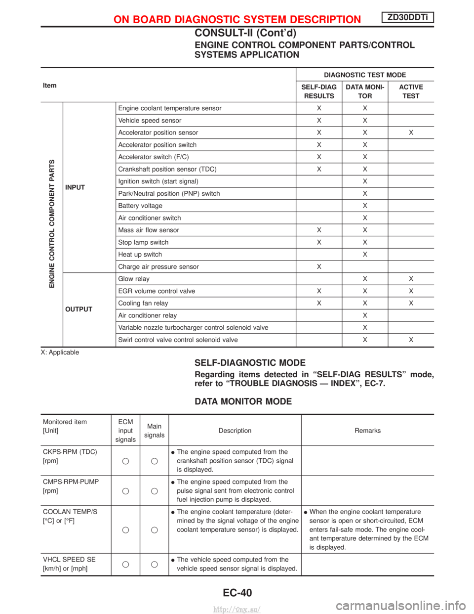
ENGINE CONTROL COMPONENT PARTS/CONTROL
SYSTEMS APPLICATION
ItemDIAGNOSTIC TEST MODE
SELF-DIAG RESULTS DATA MONI-
TOR ACTIVE
TEST
ENGINE CONTROL COMPONENT PARTS
INPUT Engine coolant temperature sensor X X
Vehicle speed sensor X X
Accelerator position sensor X X X
Accelerator position switch X X
Accelerator switch (F/C) X X
Crankshaft position sensor (TDC) X X
Ignition switch (start signal) X
Park/Neutral position (PNP) switch X
Battery voltage X
Air conditioner switch X
Mass air flow sensor X X
Stop lamp switch X X
Heat up switch X
Charge air pressure sensor X
OUTPUT Glow relay
XX
EGR volume control valve X X X
Cooling fan relay X X X
Air conditioner relay X
Variable nozzle turbocharger control solenoid valve X
Swirl control valve control solenoid valve X X
X: Applicable
SELF-DIAGNOSTIC MODE
Regarding items detected in ªSELF-DIAG RESULTSº mode,
refer to ªTROUBLE DIAGNOSIS Ð INDEXº, EC-7.
DATA MONITOR MODE
Monitored item
[Unit] ECM
input
signals Main
signals Description Remarks
CKPS×RPM (TDC)
[rpm] qqI
The engine speed computed from the
crankshaft position sensor (TDC) signal
is displayed.
CMPS×RPM×PUMP
[rpm] qqI
The engine speed computed from the
pulse signal sent from electronic control
fuel injection pump is displayed.
COOLAN TEMP/S
[ÉC] or [ÉF] qqI
The engine coolant temperature (deter-
mined by the signal voltage of the engine
coolant temperature sensor) is displayed. I
When the engine coolant temperature
sensor is open or short-circuited, ECM
enters fail-safe mode. The engine cool-
ant temperature determined by the ECM
is displayed.
VHCL SPEED SE
[km/h] or [mph] qqI
The vehicle speed computed from the
vehicle speed sensor signal is displayed.
ON BOARD DIAGNOSTIC SYSTEM DESCRIPTIONZD30DDTi
CONSULT-II (Cont'd)
EC-40
http://vnx.su/
Page 316 of 1833
![NISSAN TERRANO 2004 Service Repair Manual Monitored item
[Unit]ECM
input
signals Main
signals Description Remarks
FUEL TEMP SEN
[ÉC] or [ÉF] qqI
The fuel temperature (sent from elec-
tronic control fuel injection pump) is dis-
played.
ACCEL NISSAN TERRANO 2004 Service Repair Manual Monitored item
[Unit]ECM
input
signals Main
signals Description Remarks
FUEL TEMP SEN
[ÉC] or [ÉF] qqI
The fuel temperature (sent from elec-
tronic control fuel injection pump) is dis-
played.
ACCEL](/manual-img/5/57394/w960_57394-315.png)
Monitored item
[Unit]ECM
input
signals Main
signals Description Remarks
FUEL TEMP SEN
[ÉC] or [ÉF] qqI
The fuel temperature (sent from elec-
tronic control fuel injection pump) is dis-
played.
ACCEL POS SEN [V] qqI
The accelerator position sensor signal
voltage is displayed.
FULL ACCEL SW
[ON/OFF] qqI
Indicates [ON/OFF] condition from the
accelerator position switch signal.
ACCEL SW (FC)
[OPEN/CLOSE] qqI
Indicates [OPEN/CLOSE] condition from
the accelerator switch (FC) signal.
OFF ACCEL SW
[ON/OFF] qqI
Indicates [ON/OFF] condition from the
accelerator position switch signal.
SPILL/V [ÉCA] qI
The control position of spill valve (sent
from electronic control fuel injection
pump) is displayed.
BATTERY VOLT [V] qqI
The power supply voltage of ECM is dis-
played.
P/N POSI SW
[ON/OFF] qqI
Indicates [ON/OFF] condition from the
park/neutral position switch signal.
START SIGNAL
[ON/OFF] qqI
Indicates [ON/OFF] condition from the
starter signal. I
After starting the engine, [OFF] is dis-
played regardless of the starter signal.
AIR COND SIG
[ON/OFF] qqI
Indicates [ON/OFF] condition of the air
conditioner switch as determined by the
air conditioner signal.
BRAKE SW [ON/OFF] qqI
Indicates [ON/OFF] condition from the
stop lamp switch signal.
IGN SW
[ON/OFF] qqI
Indicates [ON/OFF] condition from igni-
tion switch signal.
WARM UP SW
[ON/OFF] qI
Indicates [ON/OFF] condition from the
heat up switch signal.
MAS AIR/FL SE [V] qqI
The signal voltage of the mass air flow
sensor is displayed. I
When the engine is stopped, a certain
value is indicated.
DECELER F/CUT
[ON/OFF] qI
The [ON/OFF] condition from decelera-
tion fuel cut signal (sent from electronic
control fuel injection pump) is displayed.
INJ TIMG C/V [%] qI
The duty ratio of fuel injection timing
control valve (sent from electronic control
fuel injection pump) is displayed.
AIR COND RLY
[ON/OFF] qI
Indicates the control condition of the air
conditioner relay (determined by ECM
according to the input signals).
GLOW RLY [ON/OFF] qI
The glow relay control condition (deter-
mined by ECM according to the input
signal) is displayed.
COOLING FAN
[ON/OFF] qI
Indicates the control condition of the
cooling fans (determined by ECM
according to the input signal).
I ON ... Operates.
OFF ... Stopped.
ON BOARD DIAGNOSTIC SYSTEM DESCRIPTIONZD30DDTi
CONSULT-II (Cont'd)
EC-41
http://vnx.su/
Page 337 of 1833
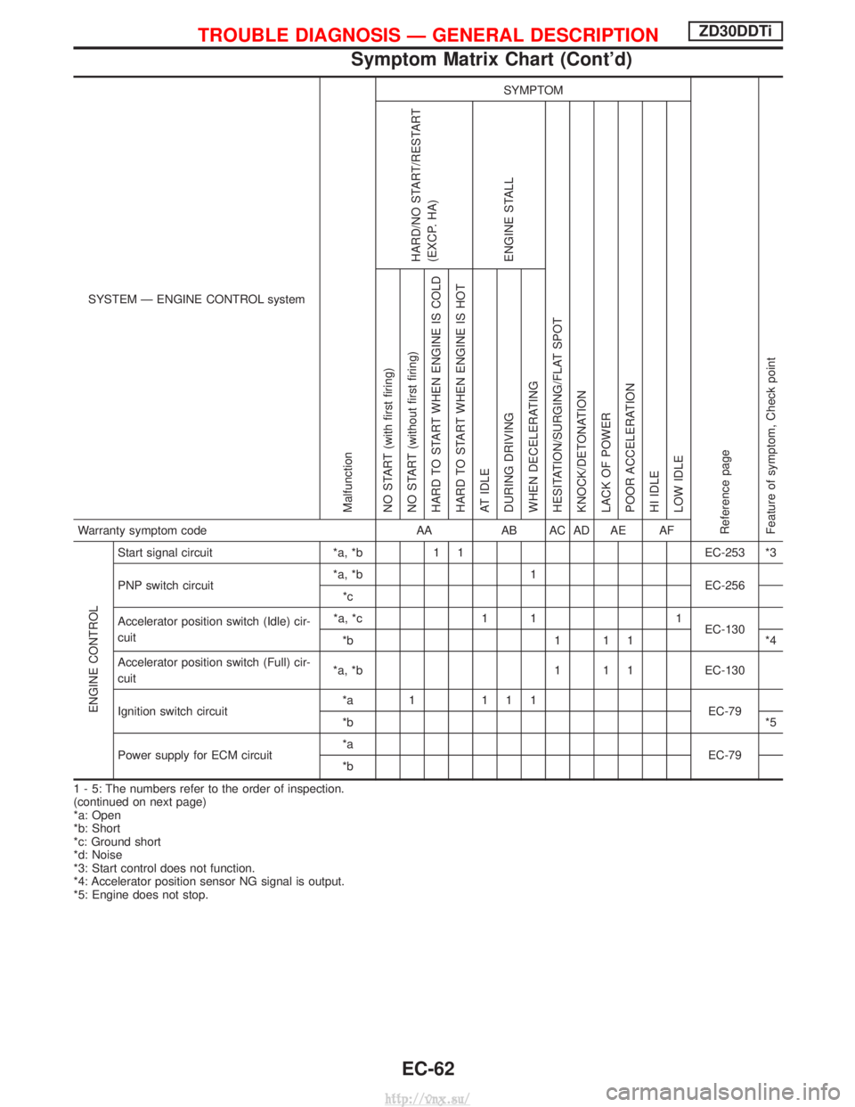
SYSTEM Ð ENGINE CONTROL system
Malfunction
SYMPTOM
Reference page
Feature of symptom, Check pointHARD/NO START/RESTART
(EXCP. HA)
ENGINE STALL
HESITATION/SURGING/FLAT SPOT
KNOCK/DETONATION
LACK OF POWER
POOR ACCELERATION
HI IDLE
LOW IDLE NO START (with first firing)
NO START (without first firing)
HARD TO START WHEN ENGINE IS COLD
HARD TO START WHEN ENGINE IS HOT
AT IDLE
DURING DRIVING
WHEN DECELERATINGWarranty symptom code AAAB AC AD AE AF
ENGINE CONTROL
Start signal circuit *a, *b1 1 EC-253 *3
PNP switch circuit *a, *b
1
EC-256
*c
Accelerator position switch (Idle) cir-
cuit *a, *c
1 1 1
EC-130
*b 1 1 1*4
Accelerator position switch (Full) cir-
cuit *a, *b
1 1 1EC-130
Ignition switch circuit *a 1 111
EC-79
*b *5
Power supply for ECM circuit *a
EC-79
*b
1 - 5: The numbers refer to the order of inspection.
(continued on next page)
*a: Open
*b: Short
*c: Ground short
*d: Noise
*3: Start control does not function.
*4: Accelerator position sensor NG signal is output.
*5: Engine does not stop.
TROUBLE DIAGNOSIS Ð GENERAL DESCRIPTIONZD30DDTi
Symptom Matrix Chart (Cont'd)
EC-62
http://vnx.su/
Page 338 of 1833
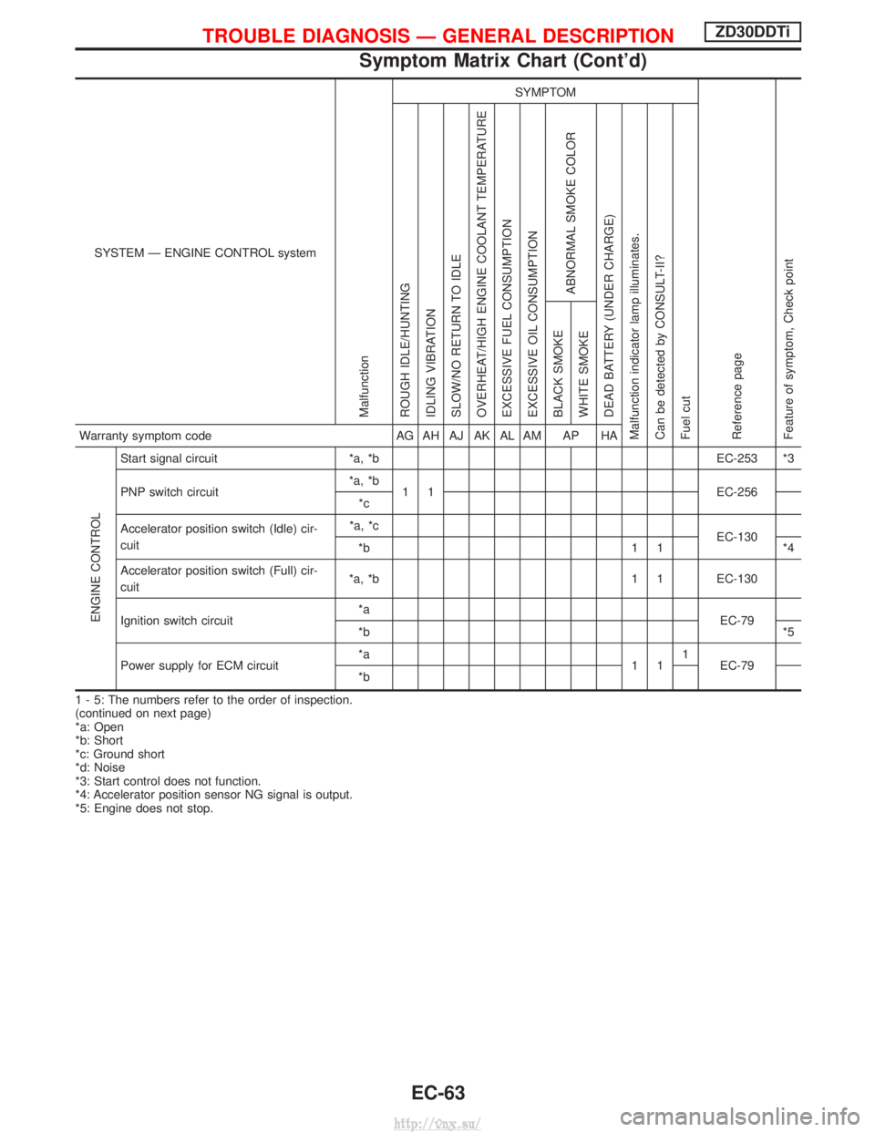
SYSTEM Ð ENGINE CONTROL system
Malfunction
SYMPTOM
Reference page
Feature of symptom, Check pointROUGH IDLE/HUNTING
IDLING VIBRATION
SLOW/NO RETURN TO IDLE
OVERHEAT/HIGH ENGINE COOLANT TEMPERATURE
EXCESSIVE FUEL CONSUMPTION
EXCESSIVE OIL CONSUMPTION
ABNORMAL SMOKE COLOR
DEAD BATTERY (UNDER CHARGE)
Malfunction indicator lamp illuminates.
Can be detected by CONSULT-II?
Fuel cut BLACK SMOKE
WHITE SMOKEWarranty symptom code
AG AH AJ AK AL AM AP HA
ENGINE CONTROL
Start signal circuit*a, *b EC-253 *3
PNP switch circuit *a, *b
1 1 EC-256
*c
Accelerator position switch (Idle) cir-
cuit *a, *c
EC-130
*b 1 1 *4
Accelerator position switch (Full) cir-
cuit *a, *b 1 1 EC-130
Ignition switch circuit *a
EC-79
*b *5
Power supply for ECM circuit *a
111
EC-79
*b
1 - 5: The numbers refer to the order of inspection.
(continued on next page)
*a: Open
*b: Short
*c: Ground short
*d: Noise
*3: Start control does not function.
*4: Accelerator position sensor NG signal is output.
*5: Engine does not stop.
TROUBLE DIAGNOSIS Ð GENERAL DESCRIPTIONZD30DDTi
Symptom Matrix Chart (Cont'd)
EC-63
http://vnx.su/