2004 NISSAN TERRANO belt
[x] Cancel search: beltPage 1191 of 1833
Removal and Installation
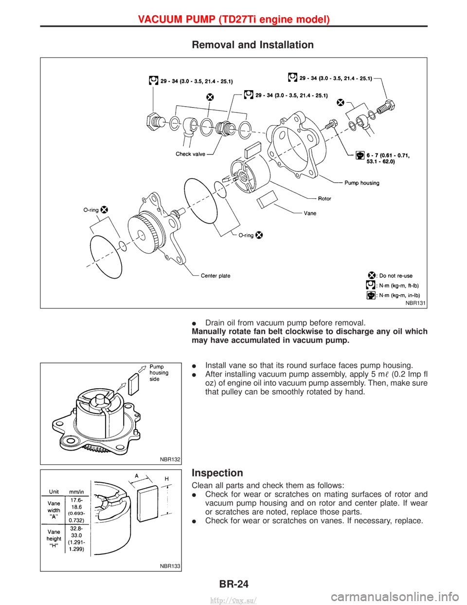
IDrain oil from vacuum pump before removal.
Manually rotate fan belt clockwise to discharge any oil which
may have accumulated in vacuum pump.
I Install vane so that its round surface faces pump housing.
I After installing vacuum pump assembly, apply 5 m (0.2 Imp fl
oz) of engine oil into vacuum pump assembly. Then, make sure
that pulley can be smoothly rotated by hand.
Inspection
Clean all parts and check them as follows:
I Check for wear or scratches on mating surfaces of rotor and
vacuum pump housing and on rotor and center plate. If wear
or scratches are noted, replace those parts.
I Check for wear or scratches on vanes. If necessary, replace.
NBR131
NBR132
NBR133
VACUUM PUMP (TD27Ti engine model)
BR-24
http://vnx.su/
Page 1254 of 1833
STEERING SYSTEM
SECTION
ST
CONTENTS
PRECAUTIONS ...............................................................2
Supplemental Restraint System (SRS) ²AIR
BAG² and²SEAT BELT PRE-TENSIONER² ...............2
Precautions for SRS ²AIR BAG² and²SEAT
BELT PRE-TENSIONER² Service ...............................2
Precautions for Steering System .................................2
PREPARATION ................................................................3
Special Service Tools ..................................................3
ON-VEHICLE SERVICE ..................................................4
Checking Steering Wheel Play ....................................4
Checking Neutral Position on Steering Wheel ............4
Front Wheel Turning Angle ..........................................4
Checking and Adjusting Drive Belts ............................4
Checking Fluid Level ...................................................4
Checking Fluid Leakage ..............................................5
Bleeding Hydraulic System..........................................5
Checking Steering Wheel Turning Force ....................6
Checking Hydraulic System.........................................7 STEERING WHEEL AND STEERING COLUMN
............8
Removal and Installation .............................................8
Disassembly and Assembly .......................................10
Inspection................................................................... 11
POWER STEERING GEAR ...........................................12
Description .................................................................12
Removal and Installation ...........................................14
Inspection and Adjustment ........................................15
POWER STEERING OIL PUMP ....................................16
Removal and Installation ...........................................16
STEERING LINKAGE ....................................................17
Removal and Installation ...........................................17
Disassembly and Assembly .......................................19
Inspection...................................................................20
SERVICE DATA AND SPECIFICATIONS (SDS) ..........22
General Specifications ...............................................22
Inspection and Adjustment ........................................22
http://vnx.su/
Page 1255 of 1833
Supplemental Restraint System (SRS) ªAIR
BAGº and ªSEAT BELT PRE-TENSIONERº
The Supplemental Restraint System such as ªAIR BAGº and ªSEAT BELT PRE-TENSIONERº used along with
a seat belt, helps to reduce the risk or severity of injury to the driver and front passenger for certain types of
collision. The SRS composition which is available to NISSAN MODEL R20 is as follows (The composition
varies according to the destination and optional equipment.):
IFor a frontal collision
The Supplemental Restraint System consists of driver air bag module (located in the center of the steer-
ing wheel), front passenger air bag module (located on the instrument panel on passenger side), front seat
belt pre-tensioners, a diagnosis sensor unit, warning lamp, wiring harness and spiral cable.
I For a side collision
The Supplemental Restraint System consists of front side air bag module (located in the outer side of front
seat), side air bag (satellite) sensor, diagnosis sensor unit (one of components of air bags for a frontal
collision), wiring harness, warning lamp (one of components of air bags for a frontal collision).
WARNING:
I To avoid rendering the SRS inoperative, which could increase the risk of personal injury or death
in the event of a collision which would result in air bag inflation, all maintenance should be per-
formed by an authorized NISSAN dealer.
I Improper maintenance, including incorrect removal and installation of the SRS, can lead to per-
sonal injury caused by unintentional activation of the system.
I Do not use electrical test equipment on any circuit related to the SRS unless instructed to in this
Service Manual. Spiral cable and wiring harnesses covered with yellow insulation tape either just
before the harness connectors or for the complete harness are related to the SRS.
Precautions for SRS ªAIR BAGº and ªSEAT
BELT PRE-TENSIONERº Service
IDo not use electrical test equipment to check SRS circuits unless instructed to in this Service Manual.
I Before servicing the SRS, turn ignition switch ªOFFº, disconnect both battery cables and wait at least 3
minutes.
For approximately 3 minutes after the cables are removed, it is still possible for the air bag and seat belt
pre-tensioner to deploy. Therefore, do not work on any SRS connectors or wires until at least 3 minutes
have passed.
I Diagnosis sensor unit must always be installed with their arrow marks ª +º pointing towards the front of
the vehicle for proper operation. Also check diagnosis sensor unit for cracks, deformities or rust before
installation and replace as required.
I The spiral cable must be aligned with the neutral position since its rotations are limited. Do not attempt to
turn steering wheel or column after removal of steering gear.
I Handle air bag module carefully. Always place driver and front passenger air bag modules with the pad
side facing upward and place front side air bag module (built-in type) standing with stud bolt side setting
bottom.
I Conduct self-diagnosis to check entire SRS for proper function after replacing any components.
I After air bag inflates, the front instrument panel assembly should be replaced if damaged.
Precautions for Steering System
IBefore disassembly, thoroughly clean the outside of the unit.
I Disassembly should be done in a clean work area. It is important to prevent the internal parts from
becoming contaminated by dirt or other foreign matter.
I When disassembling parts, be sure to place them in order on a part rack so they can be reinstalled
in their proper positions.
I Use nylon cloths or paper towels to clean the parts; common shop rags can leave lint that might
interfere with their operation.
I Before inspection or reassembly, carefully clean all parts with a general purpose, non-flammable
solvent.
I Before assembly, apply a coat of recommended ATF* to hydraulic parts. Vaseline may be applied
to O-rings and seals. Do not use any grease.
I Replace all gaskets, seals and O-rings. Avoid damaging O-rings, seals and gaskets during instal-
lation. Perform functional tests whenever designated.
*: Automatic transmission fluid
PRECAUTIONS
ST-2
http://vnx.su/
Page 1257 of 1833
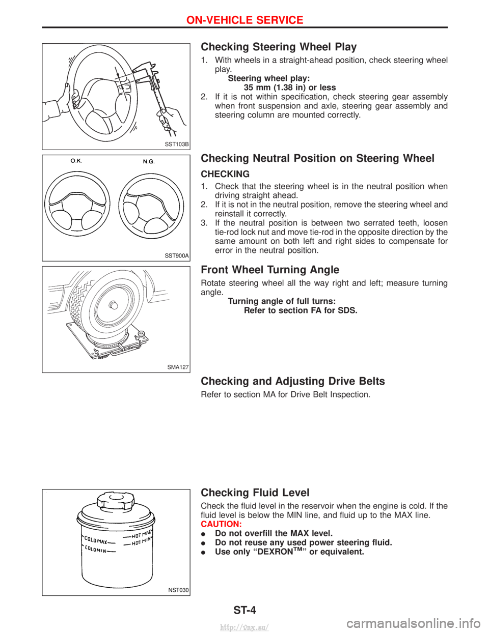
Checking Steering Wheel Play
1. With wheels in a straight-ahead position, check steering wheelplay.Steering wheel play: 35 mm (1.38 in) or less
2. If it is not within specification, check steering gear assembly when front suspension and axle, steering gear assembly and
steering column are mounted correctly.
Checking Neutral Position on Steering Wheel
CHECKING
1. Check that the steering wheel is in the neutral position whendriving straight ahead.
2. If it is not in the neutral position, remove the steering wheel and reinstall it correctly.
3. If the neutral position is between two serrated teeth, loosen tie-rod lock nut and move tie-rod in the opposite direction by the
same amount on both left and right sides to compensate for
error in the neutral position.
Front Wheel Turning Angle
Rotate steering wheel all the way right and left; measure turning
angle. Turning angle of full turns:Refer to section FA for SDS.
Checking and Adjusting Drive Belts
Refer to section MA for Drive Belt Inspection.
Checking Fluid Level
Check the fluid level in the reservoir when the engine is cold. If the
fluid level is below the MIN line, and fluid up to the MAX line.
CAUTION:
IDo not overfill the MAX level.
I Do not reuse any used power steering fluid.
I Use only ªDEXRON
TMº or equivalent.
SST103B
SST900A
SMA127
NST030
ON-VEHICLE SERVICE
ST-4
http://vnx.su/
Page 1260 of 1833
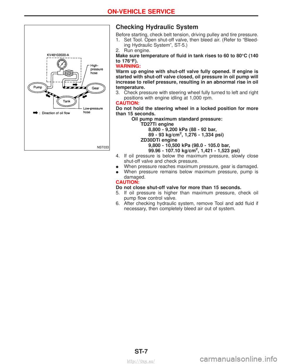
Checking Hydraulic System
Before starting, check belt tension, driving pulley and tire pressure.
1. Set Tool. Open shut-off valve, then bleed air. (Refer to ªBleed-ing Hydraulic Systemº, ST-5.)
2. Run engine.
Make sure temperature of fluid in tank rises to 60 to 80ÉC (140
to 176ÉF).
WARNING:
Warm up engine with shut-off valve fully opened. If engine is
started with shut-off valve closed, oil pressure in oil pump will
increase to relief pressure, resulting in an abnormal rise in oil
temperature.
3. Check pressure with steering wheel fully turned to left and right positions with engine idling at 1,000 rpm.
CAUTION:
Do not hold the steering wheel in a locked position for more
than 15 seconds. Oil pump maximum standard pressure:TD27Ti engine8,800 - 9,200 kPa (88 - 92 bar,
89 - 93 kg/cm
2, 1,276 - 1,334 psi)
ZD30DTi engine 9,800 - 10,500 kPa (98.0 - 105.0 bar,
99.96 - 107.10 kg/cm
2, 1,421 - 1,523 psi)
4. If oil pressure is below the maximum pressure, slowly close shut-off valve and check pressure.
I When pressure reaches maximum pressure, gear is damaged.
I When pressure remains below maximum pressure, pump is
damaged.
CAUTION:
Do not close shut-off valve for more than 15 seconds.
5. If oil pressure is higher than maximum pressure, check oil pump flow control valve.
6. After checking hydraulic system, remove Tool and add fluid if necessary, then completely bleed air out of system.NST033
ON-VEHICLE SERVICE
ST-7
http://vnx.su/
Page 1276 of 1833
RESTRAINT SYSTEM
SECTION
RS
CONTENTS
SEAT BELTS ...................................................................2
Precautions ..................................................................2
Front Seat Belt.............................................................4
Rear Seat Belt .............................................................6
SUPPLEMENTAL RESTRAINT SYSTEM (SRS) ............8
Precautions ..................................................................8
Preparation ..................................................................9
SRS Configuration .....................................................10
Seat Belt Pre-tensioner with Load Limiter................. 11
Built-in Type Side Air Bag.......................................... 11
SRS Component Parts Location ...............................12
Maintenance Items ....................................................12
Diagnosis Sensor Unit ...............................................13
Front Seat Belt Pre-tensioner ....................................14
Side Air Bag (Satellite) Sensor ..................................15
Driver Air Bag Module and Spiral Cable ...................16
Front Passenger Air Bag Module ..............................19 Front Side Air Bag Module ........................................20
Disposal of Air Bag Module and Seat Belt Pre-
tensioner ....................................................................22
Trouble Diagnoses Introduction.................................28
How to Perform Trouble Diagnoses for Quick
and Accurate Repair ..................................................31
Schematic ..................................................................33
Wiring Diagram - SRS -.............................................34
SRS Operation Check ...............................................38
Trouble Diagnoses with CONSULT-II..................39
Trouble Diagnoses without CONSULT-II.............48
Trouble Diagnoses: ²AIR BAG² Warning Lamp
Does Not Turn Off .....................................................56
Trouble Diagnoses: ²AIR BAG² Warning Lamp
Does Not Turn On .....................................................58
Collision Diagnosis ....................................................59
http://vnx.su/
Page 1277 of 1833
Precautions
SUPPLEMENTAL RESTRAINT SYSTEM (SRS) ªAIR BAGº AND ªSEAT BELT
PRE-TENSIONERº
The Supplemental Restraint System such as ªAIR BAGº and ªSEAT BELT PRE-TENSIONERº used along with
a seat belt, helps to reduce the risk or severity of injury to the driver and front passenger for certain types of
collision. The SRS composition which is available to NISSAN MODEL R20 is as follows (The composition
varies according to the destination and optional equipment.):
IFor a frontal collision
The Supplemental Restraint System consists of driver air bag module (located in the center of the steer-
ing wheel), front passenger air bag module (located on the instrument panel on passenger side), front seat
belt pre-tensioners, a diagnosis sensor unit, warning lamp, wiring harness and spiral cable.
I For a side collision
The Supplemental Restraint System consists of front side air bag module (located in the outer side of front
seat), side air bag (satellite) sensor, diagnosis sensor unit (one of components of air bags for a frontal
collision), wiring harness, warning lamp (one of components of air bags for a frontal collision).
WARNING:
I To avoid rendering the SRS inoperative, which could increase the risk of personal injury or death
in the event of a collision which would result in air bag inflation, all maintenance should be per-
formed by an authorized NISSAN dealer.
I Improper maintenance, including incorrect removal and installation of the SRS, can lead to per-
sonal injury caused by unintentional activation of the system.
I Do not use electrical test equipment on any circuit related to the SRS unless instructed to in this
Service Manual. Spiral cable and wiring harnesses covered with yellow insulation tape either just
before the harness connectors or for the complete harness are related to the SRS.
Precaution for Seat Belt Service
CAUTION:
IBefore removing the seat belt pre-tensioner assembly, turn the ignition switch off, disconnect both
battery cables and wait at least 3 minutes.
I Do not use electrical test equipment for seat belt pre-tensioner connector.
I After replacing or reinstalling seat belt pre-tensioner assembly, or reconnecting seat belt pre-ten-
sioner connector, check the system function. Refer to ªSRS Operation Checkº for details. (RS-38)
I Do not disassemble buckle or seat belt assembly.
I Replace anchor bolts if they are deformed or worn out.
I Never oil tongue and buckle.
I If any component of seat belt assembly is questionable, do not repair. Replace the whole seat belt
assembly.
I If webbing is cut, frayed, or damaged, replace seat belt assembly.
I When replacing seat belt assembly, use a genuine seat belt assembly.
After A Collision
WARNING:
Inspect all seat belt assemblies including retractors and attaching hardware after any collision.
NISSAN recommends that all seat belt assemblies in use during a collision be replaced unless the
collision was minor and the belts show no damage and continue to operate properly. Failure to do so
could result in serious personal injury in an accident. Seat belt assemblies not in use during a colli-
sion should also be replaced if either damage or improper operation is noted. Seat belt pre-tensioner
should be replaced even if the seat belts are not in use during a frontal collision in which the air bags
are deployed.
Replace any seat belt assembly if:
IThe seat belt was in use at the time of a collision (except for minor collisions and the belts, retractors and
buckles show no damage and continue to operate properly).
I The seat belt was damaged in an accident. (i.e. torn webbing, bent retractor or guide, etc.)
I The seat belt attaching point was damaged in an accident. Inspect the seat belt attaching area for dam-
age or distortion and repair as necessary before installing a new seat belt assembly.
I Anchor bolts are deformed or worn out.
SEAT BELTS
RS-2
http://vnx.su/
Page 1278 of 1833

YRS137
SEAT BELTS
Precautions (Cont'd)RS-3
http://vnx.su/