2004 NISSAN TERRANO belt
[x] Cancel search: beltPage 49 of 1833
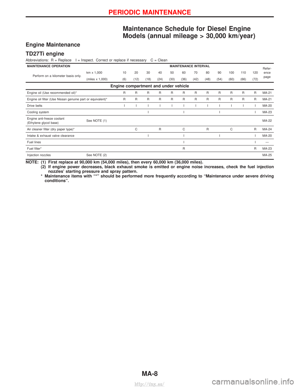
Maintenance Schedule for Diesel Engine
Models (annual mileage > 30,000 km/year)
Engine Maintenance
TD27Ti engine
Abbreviations: R = Replace I = Inspect. Correct or replace if necessary C = Clean
MAINTENANCE OPERATIONMAINTENANCE INTERVAL
Refer-
ence
page
Perform on a kilometer basis only. km x 1,000 10 20 30 40 50 60 70 80 90 100 110 120
(miles x 1,000) (6) (12) (18) (24) (30) (36) (42) (48) (54) (60) (66) (72)
Engine compartment and under vehicle
Engine oil (Use recommended oil)*
RRRRRRRRRRRR MA-21
Engine oil filter (Use Nissan genuine part or equivalent)* RRRRRRRRRRRR MA-21
Drive belts IIIIIIIIIIII MA-20
Cooling system IIIIMA-23
Engine anti-freeze coolant
(Ethylene glycol base) See NOTE (1)
MA-22
Air cleaner filter (dry paper type)* CRCRCR MA-24
Intake & exhaust valve clearance IIIIMA-20
Fuel lines IIÐ
Fuel filter* R R MA-23
Injection nozzles See NOTE (2) MA-25
NOTE: (1) First replace at 90,000 km (54,000 miles), then every 60,000 km (36,000 miles).
(2) If engine power decreases, black exhaust smoke is emitted or engine noise increases, check the fuel injectionnozzles' starting pressure and spray pattern.
* Maintenance items with ª*º should be performed more frequently according to ªMaintenance under severe driving conditionsº.
PERIODIC MAINTENANCE
MA-8
http://vnx.su/
Page 50 of 1833
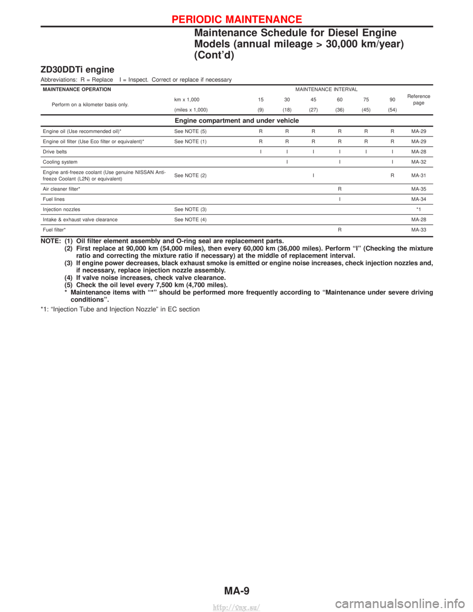
ZD30DDTi engine
Abbreviations: R = Replace I = Inspect. Correct or replace if necessary
MAINTENANCE OPERATIONMAINTENANCE INTERVAL
Referencepage
Perform on a kilometer basis only. km x 1,000 15 30 45 60 75 90
(miles x 1,000) (9) (18) (27) (36) (45) (54)
Engine compartment and under vehicle
Engine oil (Use recommended oil)*
See NOTE (5)RRRRRR MA-29
Engine oil filter (Use Eco filter or equivalent)* See NOTE (1) RRRRRRMA-29
Drive belts IIIIIIMA-28
Cooling system I I I MA-32
Engine anti-freeze coolant (Use genuine NISSAN Anti-
freeze Coolant (L2N) or equivalent) See NOTE (2) I R MA-31
Air cleaner filter* R MA-35
Fuel lines I MA-34
Injection nozzles See NOTE (3) *1
Intake & exhaust valve clearance See NOTE (4) MA-28
Fuel filter* R MA-33
NOTE: (1) Oil filter element assembly and O-ring seal are replacement parts.
(2) First replace at 90,000 km (54,000 miles), then every 60,000 km (36,000 miles). Perform ªIº (Checking the mixtureratio and correcting the mixture ratio if necessary) at the middle of replacement interval.
(3) If engine power decreases, black exhaust smoke is emitted or engine noise increases, check injection nozzles and, if necessary, replace injection nozzle assembly.
(4) If valve noise increases, check valve clearance.
(5) Check the oil level every 7,500 km (4,700 miles).
* Maintenance items with ª*º should be performed more frequently according to ªMaintenance under severe driving conditionsº.
*1: ªInjection Tube and Injection Nozzleº in EC section
PERIODIC MAINTENANCE
Maintenance Schedule for Diesel Engine
Models (annual mileage > 30,000 km/year)
(Cont'd)
MA-9
http://vnx.su/
Page 61 of 1833
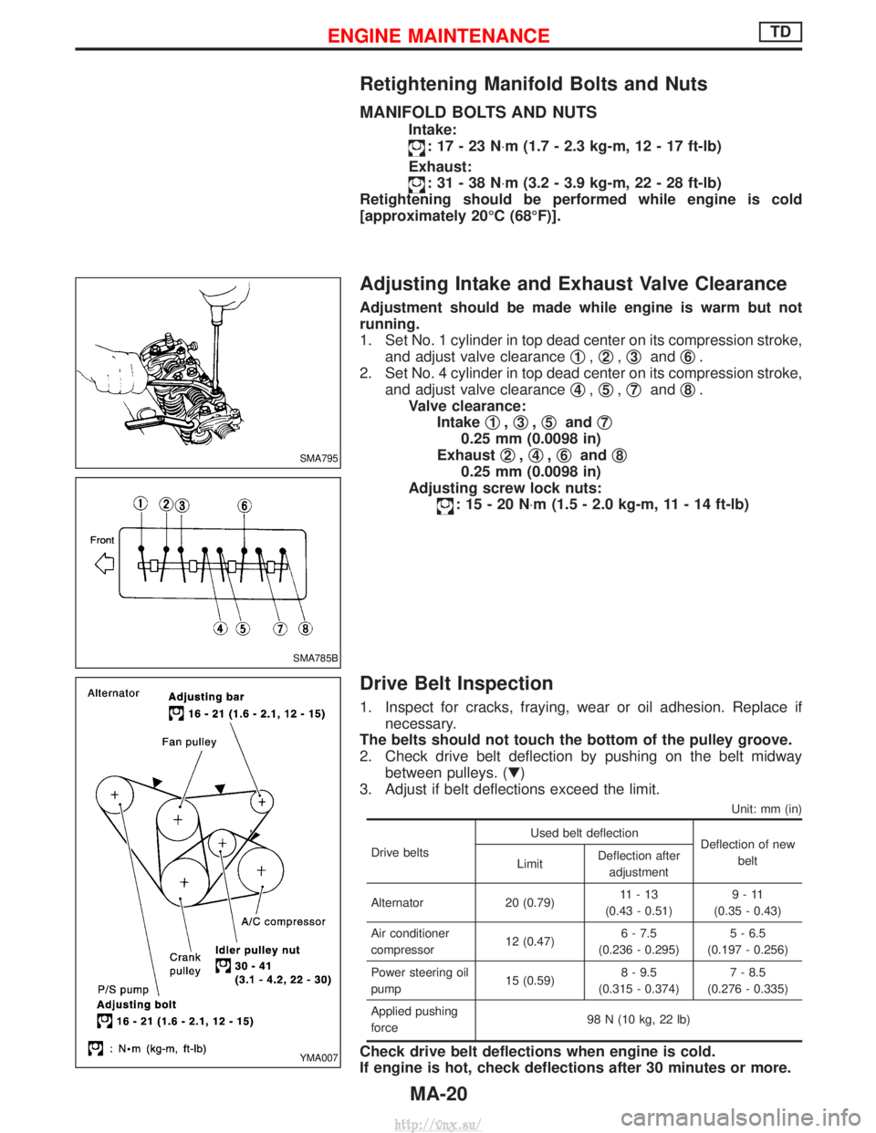
Retightening Manifold Bolts and Nuts
MANIFOLD BOLTS AND NUTS
Intake:
:17-23N×m (1.7 - 2.3 kg-m, 12 - 17 ft-lb)
Exhaust:
:31-38N ×m (3.2 - 3.9 kg-m, 22 - 28 ft-lb)
Retightening should be performed while engine is cold
[approximately 20ÉC (68ÉF)].
Adjusting Intake and Exhaust Valve Clearance
Adjustment should be made while engine is warm but not
running.
1. Set No. 1 cylinder in top dead center on its compression stroke, and adjust valve clearance q
1,q2,q3and q6.
2. Set No. 4 cylinder in top dead center on its compression stroke, and adjust valve clearance q
4,q5,q7and q8.
Valve clearance: Intake q
1,q3,q5and q7
0.25 mm (0.0098 in)
Exhaust q
2,q4,q6and q8
0.25 mm (0.0098 in)
Adjusting screw lock nuts:
:15-20N ×m (1.5 - 2.0 kg-m, 11 - 14 ft-lb)
Drive Belt Inspection
1. Inspect for cracks, fraying, wear or oil adhesion. Replace if
necessary.
The belts should not touch the bottom of the pulley groove.
2. Check drive belt deflection by pushing on the belt midway between pulleys. (H)
3. Adjust if belt deflections exceed the limit.
Unit: mm (in)
Drive belts Used belt deflection
Deflection of new
belt
Limit Deflection after
adjustment
Alternator 20 (0.79) 11-13
(0.43 - 0.51) 9-11
(0.35 - 0.43)
Air conditioner
compressor 12 (0.47)6 - 7.5
(0.236 - 0.295) 5 - 6.5
(0.197 - 0.256)
Power steering oil
pump 15 (0.59)8 - 9.5
(0.315 - 0.374) 7 - 8.5
(0.276 - 0.335)
Applied pushing
force 98 N (10 kg, 22 lb)
Check drive belt deflections when engine is cold.
If engine is hot, check deflections after 30 minutes or more.
SMA795
SMA785B
YMA007
ENGINE MAINTENANCETD
MA-20
http://vnx.su/
Page 69 of 1833
Checking Tightening Torque
Checking should be performed while engine is cold.
MANIFOLD BOLTS AND NUTS
Intake and exhaust manifolds:Intake
:25-28N ×m (2.5 - 2.9 kg-m, 18 - 20 ft-lb)
Exhaust
:40-44N ×m (4.0 - 4.5 kg-m, 29 - 32 ft-lb)
Adjusting Intake and Exhaust Valve Clearance
Refer to EM section.
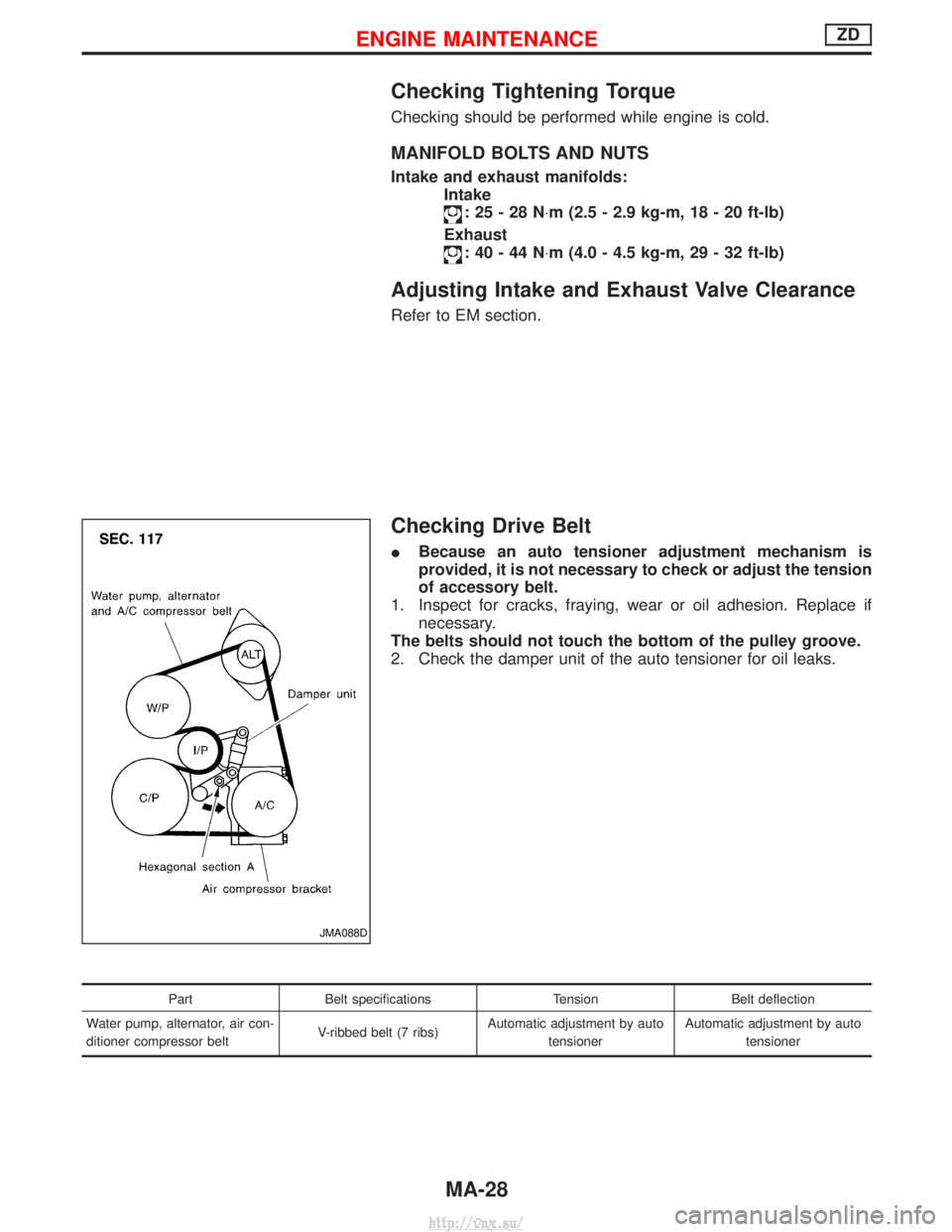
Checking Drive Belt
IBecause an auto tensioner adjustment mechanism is
provided, it is not necessary to check or adjust the tension
of accessory belt.
1. Inspect for cracks, fraying, wear or oil adhesion. Replace if necessary.
The belts should not touch the bottom of the pulley groove.
2. Check the damper unit of the auto tensioner for oil leaks.
Part Belt specifications TensionBelt deflection
Water pump, alternator, air con-
ditioner compressor belt V-ribbed belt (7 ribs)Automatic adjustment by auto
tensioner Automatic adjustment by auto
tensioner
JMA088D
ENGINE MAINTENANCEZD
MA-28
http://vnx.su/
Page 70 of 1833

Removal
WATER PUMP, ALTERNATOR AND AIR CONDITIONER
BELT
1. Remove radiator shroud.
2. Contract and hold the auto tensioner using the following proce-dure.
a. Securely hold the 19 mm (0.75 in) hexagonal portion A of auto tensioner with a closed wrench.
I Preferably use a tool with a handhold of 500 mm (19.69 in) or
more in length.
I No bolts or nuts are required to be loosened during the opera-
tion.
b. Turn the hexagonal portion A in the direction shown by the arrow to contract the damper unit of the auto tensioner.
CAUTION:
I Because the tensioner has a high tension, it shall be
securely held and turned with a closed wrench.
I Because the hexagonal portion A of the tensioner is made
of aluminum and may be damaged by sudden input, turn
it slowly according to the contraction of the damper unit.
3. Remove the belt from the alternator pulley first, and then remove it from the other pulleys.
I If the tensioner is not held firmly, your finger may get caught
between the belt and the pulleys. Confirm the holding of the
tensioner, and then hold the belt side in the place away from
the pulleys to attach or remove the belt, paying attention to
prevent your finger from being caught.
CAUTION:
I When handling the belt, pay attention to prevent the oil or
coolant from adhering to the belt.
I Do not distort or bend the belt intensively.
Installation
IInstall the belt in the reverse order of removal.
I After installation of the belt, confirm that the belt engages the
pulleys securely.
I Depending on the engagement between the belt and the idler
pulley, noise (belt noise) may be heard when the engine is
started just after installation. This noise will stop with time.
Changing Engine Oil
WARNING:
IBe careful not to burn yourself, as engine oil is hot.
I Prolonged and repeated contact with used engine oil may
cause skin cancer; try to avoid direct skin contact with
used oil. If skin contact is made, wash thoroughly with
soap or hand cleaner as soon as possible.
1. Warm up engine, and check for oil leakage from engine com- ponents.
2. Remove drain plug and oil filler cap.
SMA101D
ENGINE MAINTENANCEZD
MA-29
http://vnx.su/
Page 87 of 1833
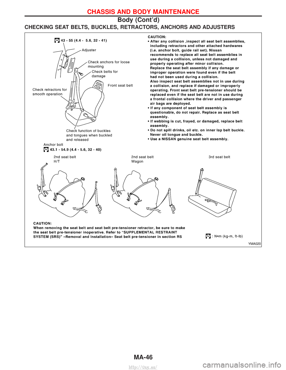
CHECKING SEAT BELTS, BUCKLES, RETRACTORS, ANCHORS AND ADJUSTERS
YMA020
CHASSIS AND BODY MAINTENANCE
Body (Cont'd)MA-46
http://vnx.su/
Page 89 of 1833
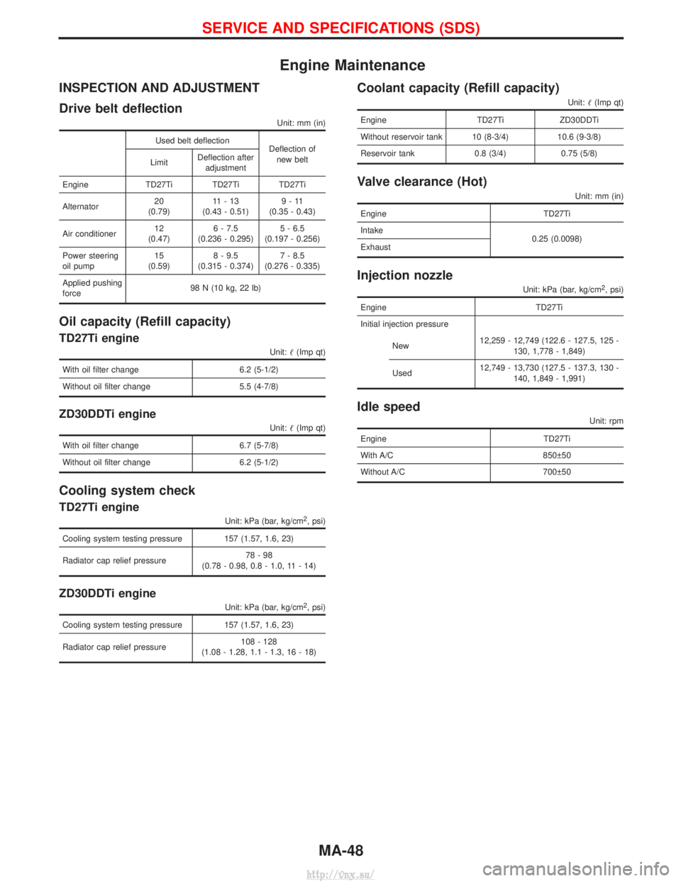
Engine Maintenance
INSPECTION AND ADJUSTMENT
Drive belt deflection
Unit: mm (in)
Used belt deflectionDeflection of
new belt
Limit Deflection after
adjustment
Engine TD27Ti TD27Ti TD27Ti
Alternator 20
(0.79) 11-13
(0.43 - 0.51) 9-11
(0.35 - 0.43)
Air conditioner 12
(0.47) 6 - 7.5
(0.236 - 0.295) 5 - 6.5
(0.197 - 0.256)
Power steering
oil pump 15
(0.59) 8 - 9.5
(0.315 - 0.374) 7 - 8.5
(0.276 - 0.335)
Applied pushing
force 98 N (10 kg, 22 lb)
Oil capacity (Refill capacity)
TD27Ti engine
Unit:
(Imp qt)
With oil filter change 6.2 (5-1/2)
Without oil filter change 5.5 (4-7/8)
ZD30DDTi engine
Unit: (Imp qt)
With oil filter change 6.7 (5-7/8)
Without oil filter change 6.2 (5-1/2)
Cooling system check
TD27Ti engine
Unit: kPa (bar, kg/cm2, psi)
Cooling system testing pressure 157 (1.57, 1.6, 23)
Radiator cap relief pressure 78-98
(0.78 - 0.98, 0.8 - 1.0, 11 - 14)
ZD30DDTi engine
Unit: kPa (bar, kg/cm2, psi)
Cooling system testing pressure 157 (1.57, 1.6, 23)
Radiator cap relief pressure 108 - 128
(1.08 - 1.28, 1.1 - 1.3, 16 - 18)
Coolant capacity (Refill capacity)
Unit: (Imp qt)
Engine TD27TiZD30DDTi
Without reservoir tank 10 (8-3/4) 10.6 (9-3/8)
Reservoir tank 0.8 (3/4) 0.75 (5/8)
Valve clearance (Hot)
Unit: mm (in)
Engine TD27Ti
Intake 0.25 (0.0098)
Exhaust
Injection nozzle
Unit: kPa (bar, kg/cm2, psi)
Engine TD27Ti
Initial injection pressure
New 12,259 - 12,749 (122.6 - 127.5, 125 -
130, 1,778 - 1,849)
Used 12,749 - 13,730 (127.5 - 137.3, 130 -
140, 1,849 - 1,991)
Idle speed
Unit: rpm
Engine TD27Ti
With A/C 850 50
Without A/C 700 50
SERVICE AND SPECIFICATIONS (SDS)
MA-48
http://vnx.su/
Page 100 of 1833
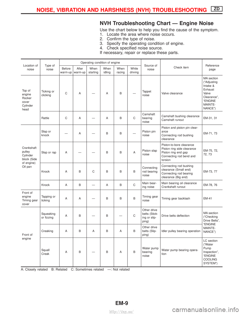
NVH Troubleshooting Chart Ð Engine Noise
Use the chart below to help you find the cause of the symptom.
1. Locate the area where noise occurs.
2. Confirm the type of noise.
3. Specify the operating condition of engine.
4. Check specified noise source.
If necessary, repair or replace these parts.
Location ofnoise Type of
noise Operating condition of engine
Source of
noise Check item Reference
page
Before
warm-up After
warm-up When
starting When
idling When
racing While
driving
To p o f
engine
Rocker
cover
Cylinder
head Ticking or
clicking
C AÐA BÐ Tappet
noiseValve clearance MA section
(ªAdjusting
Intake &
Exhaust
Valve
Clearanceº,
ªENGINE
MAINTE-
NANCEº)
Rattle C A Ð A B C Camshaft
bearing
noiseCamshaft bushing clearance
Camshaft runout
EM-31, 31
Crankshaft
pulley
Cylinder
block (Side
of engine)
Oil pan Slap or
knock
ÐAÐB BÐ Piston pin
noisePiston and piston pin clear-
ance
Connecting rod bushing
clearance
EM-71, 73
Slap or rap A Ð Ð B B A Piston slap
noisePiston-to-bore clearance
Piston ring side clearance
Piston ring end gap
Connecting rod bend and
torsion EM-75, 72,
72, 73
Knock A B C B B B Connecting
rod bearing
noiseConnecting rod bushing
clearance (Small end)
Connecting rod bearing
clearance (Big end)
EM-73, 77
Knock A B Ð A B C Main bear-
ing noiseMain bearing oil clearance
Crankshaft runout
EM-78, 76
Front of
engine
Timing gear
cover Tapping or
ticking
AAÐBBB Timing gear
noiseTiming gear backlash EM-41
Front of
engine Squeaking
or fizzing
A BÐBÐC Other drive
belts (Stick-
ing or slip-
ping)Drive belts deflection
MA section
(ªChecking
Drive Beltsº,
ªENGINE
MAINTE-
NANCEº)
Creaking
ABABAB Other drive
belts (Slip-
ping)Idler pulley bearing operation
Squall
Creak ABÐBAB Water pump
bearing
noiseWater pump bearing opera-
tion LC section
(ªWater
Pump
Inspectionº,
ªENGINE
COOLING
SYSTEMº)
A: Closely related B: Related C: Sometimes related Ð: Not related
NOISE, VIBRATION AND HARSHNESS (NVH) TROUBLESHOOTINGZD
EM-9
http://vnx.su/