Page 117 of 1833
Removal and Installation
CAUTION:
As the internal mechanism of the idler gear must first of all,
and always, be set by a bolt when removing the timing chain
before removing the fuel injection pump and timing gear, fol-
low the procedures on EM-38, ªRemoval of timing chain after
setting idler gearº, ªElectronic controlled fuel injection pumpº.
IThis chapter will deal with the summary of removing the timing
chain before removing the camshaft and cylinder head.
Removal
1. Remove the following parts.
IEngine cover
I Intercooler
I Air inlet pipe
I Throttle body
I Rocker cover
I Spill tube
I Coolant (Drain)
I Radiator upper hose
I Water outlet
I Radiator shroud
I Cooling fan
I Auxiliary belt
I Vacuum pipe
I Vacuum pump
YEM028
TIMING CHAINZD
EM-26
http://vnx.su/
Page 154 of 1833
Precautions
IDo not perform operation unless it is perfectly safe.
I Do not start operation unless the exhaust system and coolant
are cooled down.
I Lift the engine at the designated support points only.
I Perform operations for the items other than the engine body,
referring to the applicable sections.
I Refer to MT section and AT section for rear mount.
Removal
IAfter removing transmission, hoist the engine and remove it.
Preparation
1. Drain coolant from radiator drain plugs.
2. Remove the following parts.
IEngine hood
I Undercover
I Under protector
I Battery
I Intercooler
I Radiator shroud
I Radiator
I Accessory belt
I Cooling fan
I Exhaust front tube
YEM032
ENGINE REMOVALZD
EM-63
http://vnx.su/
Page 159 of 1833

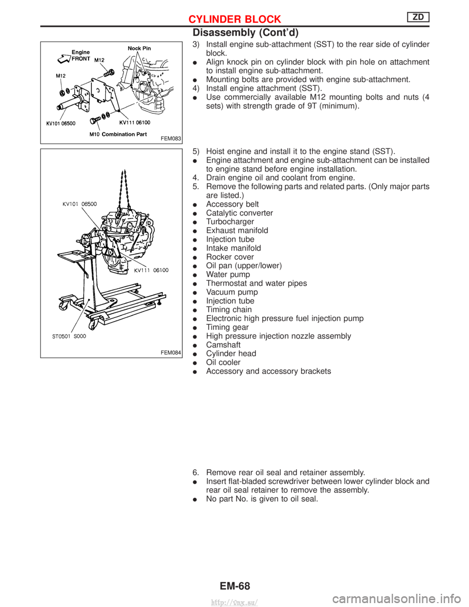
3) Install engine sub-attachment (SST) to the rear side of cylinderblock.
I Align knock pin on cylinder block with pin hole on attachment
to install engine sub-attachment.
I Mounting bolts are provided with engine sub-attachment.
4) Install engine attachment (SST).
I Use commercially available M12 mounting bolts and nuts (4
sets) with strength grade of 9T (minimum).
5) Hoist engine and install it to the engine stand (SST).
I Engine attachment and engine sub-attachment can be installed
to engine stand before engine installation.
4. Drain engine oil and coolant from engine.
5. Remove the following parts and related parts. (Only major parts are listed.)
I Accessory belt
I Catalytic converter
I Turbocharger
I Exhaust manifold
I Injection tube
I Intake manifold
I Rocker cover
I Oil pan (upper/lower)
I Water pump
I Thermostat and water pipes
I Vacuum pump
I Injection tube
I Timing chain
I Electronic high pressure fuel injection pump
I Timing gear
I High pressure injection nozzle assembly
I Camshaft
I Cylinder head
I Oil cooler
I Accessory and accessory brackets
6. Remove rear oil seal and retainer assembly.
I Insert flat-bladed screwdriver between lower cylinder block and
rear oil seal retainer to remove the assembly.
I No part No. is given to oil seal.
FEM083
FEM084
CYLINDER BLOCKZD
Disassembly (Cont'd)
EM-68
http://vnx.su/
Page 209 of 1833
OIL SEAL INSTALLING DIRECTION
IWhen installing a new front or rear oil seal, make sure its
mounting direction is correct.
CRANKSHAFT FRONT OIL SEAL
1. Remove protecting cover.
2. Remove radiator shroud.
3. Remove cooling fan.
4. Remove drive belts.
5. Remove crank pulley.
6. Remove crankshaft oil seal.
IBe careful not to damage sealing surfaces of crankshaft.
7. Coat new oil seal with engine oil and install it in place.
CRANKSHAFT REAR OIL SEAL
1. Dismount transmission.
2. Remove clutch cover assembly.
3. Remove flywheel and rear plate.
4. Remove oil seal retainer assembly, then remove oil seal.
I Be careful not to damage sealing surfaces of crankshaft.
5. Coat new oil seal with engine oil and install it in place.
SEM715A
SEM644B
SEM217B
OIL SEAL REPLACEMENTTD27Ti
EM-118
http://vnx.su/
Page 216 of 1833
Disassembly
PISTON AND CRANKSHAFT
1. Remove oil filter.
2. Place engine on work stand.
3. Drain coolant and oil.
4. Remove drive belts.
5. Remove cylinder head. Refer to ªCYLINDER HEADº.
6. Remove oil pan.
7. Remove crank pulley and timing gear plate cover.
8. Remove water pump.
9. Remove timing gear case.
If the timing case is hard to remove due to liquid gasket, pry
it off with a suitable tool at the cutout section.
10. Remove injection pump gear nut.
SEM650B
NEM165
NEM170
NEM166
NEM167
ENGINE OVERHAULTD27Ti
EM-125
http://vnx.su/
Page 249 of 1833
OIL FILTER
The oil filter is an element type. Refer to ªChanging Oil Filterº in MA
section.
Oil Cooler
REMOVAL AND INSTALLATION
1. Drain engine oil and coolant.Remove catalyst and turbocharger. Refer to ªCATALYST AND
TURBOCHARGERº in EM section.
2. Remove bolts A to C then remove oil cooler assembly.
I Do not remove ªDº nuts when removing oil cooler assem-
bly.
Bolt length: A: 20 mm (0.79 in)
B: 45 mm (1.77 in)
C: 65 mm (2.56 in)
3. Installation is in reverse order of removal.
I Do not spill coolant on the drive belt.
INSPECTION
1. Check oil cooler for cracks.
2. Check oil cooler for clogging by blowing through coolant inlet.
If necessary, replace oil cooler assembly.
YLC030
JLC381B
ENGINE LUBRICATION SYSTEMZD
Oil Jet (Cont'd)
LC-8
http://vnx.su/
Page 252 of 1833
Water Pump
CAUTION:
IWhen removing water pump assembly, be careful not to
get coolant on drive belt.
I Water pump cannot be disassembled and should be
replaced as a unit.
I Always replace with new gasket.
I After installing water pump, connect hose and clamp
securely, then check for leaks using radiator cap tester.
Refer to MA section.
REMOVAL AND INSTALLATION
1. Drain coolant from radiator and cylinder block.
Refer to MA section (ªChanging Engine Coolantº, ªENGINE
MAINTENANCEº).
2. Remove radiator upper hose.
3. Remove radiator shroud.
4. Remove cooling fan.
5. Remove drive belt. Refer to MA section, ªChecking Drive Beltº.
6. Remove insulator.
7. Remove vacuum pipe.
8. Remove TDC sensor. Refer to EM section, ªTDC sensor removal and installationº in ªTIMING GEARº.
9. Remove fan coupling with water pump.
10. Install in the reverse order of removal.
JLC373B
ENGINE COOLING SYSTEMZD
LC-11
http://vnx.su/
Page 256 of 1833

REMOVAL AND INSTALLATION
1. Remove under cover.
2. Drain engine coolant. Refer to MA section, ªChanging EngineCoolantº.
3. Remove air cleaner case, air duct and resonator.
4. Remove battery (right side).
5. Remove radiator shroud (lower).
6. Remove radiator shroud (front).
7. Disconnect radiator hose (upper and lower).
8. Disconnect reservoir tank hose.
9. Disconnect A/T oil cooler hose (Only A/T models).
10. Remove radiator.
11. After repairing or replacing radiator, install all removed parts in reverse order of removal.
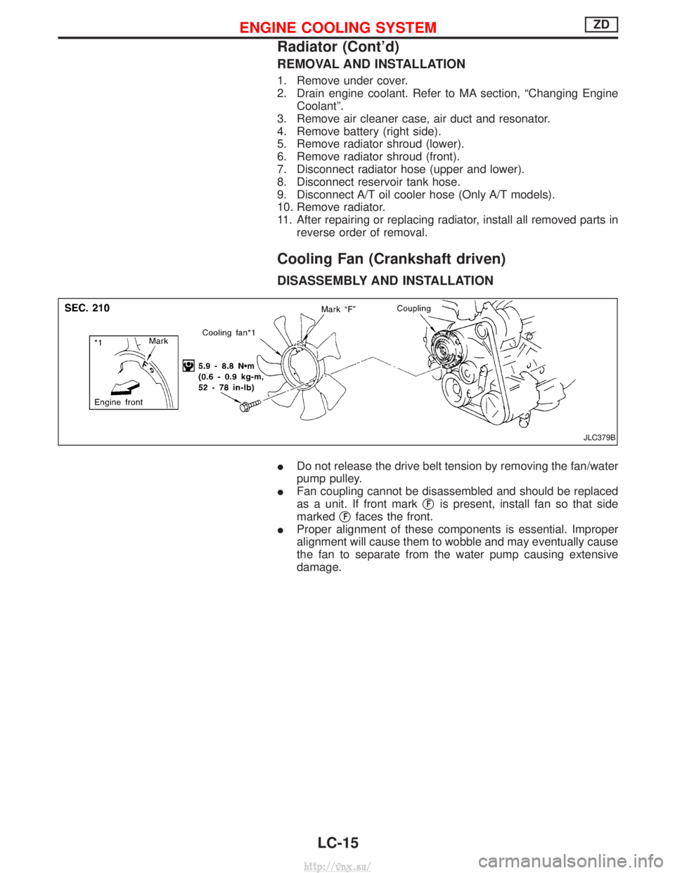
Cooling Fan (Crankshaft driven)
DISASSEMBLY AND INSTALLATION
IDo not release the drive belt tension by removing the fan/water
pump pulley.
I Fan coupling cannot be disassembled and should be replaced
as a unit. If front mark q
Fis present, install fan so that side
marked q
Ffaces the front.
I Proper alignment of these components is essential. Improper
alignment will cause them to wobble and may eventually cause
the fan to separate from the water pump causing extensive
damage.
JLC379B
ENGINE COOLING SYSTEMZD
Radiator (Cont'd)
LC-15
http://vnx.su/