Page 500 of 1833
4 DETECT MALFUNCTIONING PART
Check the following.
IHarness connectors E225, F108
I Harness connectors F135, M852 (RHD models)
I Harness for open or short between ECM and charge air pressure sensor
ERepair open circuit or short to ground or short to power in harness or connectors.
5 CHECK CHARGE AIR PRESSURE SENSOR INPUT SIGNAL CIRCUIT FOR OPEN AND SHORT
1. Disconnect ECM harness connector.
2. Check harness continuity between ECM terminal 46 and charge air pressure sensor terminal 2. Refer to Wiring Diagram.
Continuity should exist.
3. Also check harness for short to ground and short to power.
OK or NG
OK EGO TO 7.
NG EGO TO 6.
6 DETECT MALFUNCTIONING PART
Check the following.
IHarness connectors E225, F108
I Harness connectors F135, M842 (RHD models)
I Harness for open or short between charge air pressure sensor and ECM
ERepair open circuit or short to ground or short to power in harness or connectors.
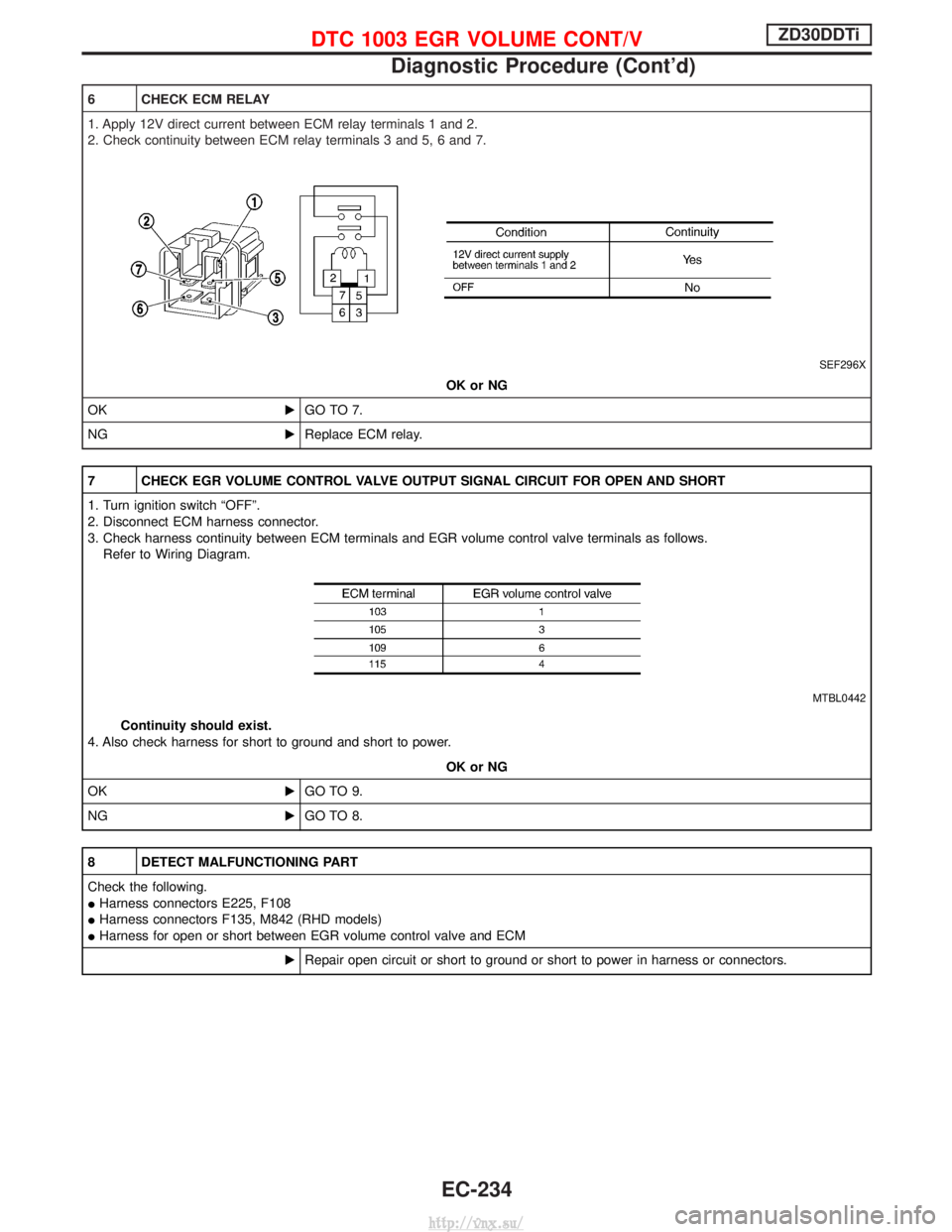
7 CHECK CHARGE AIR PRESSURE SENSOR
1. Remove charge air pressure sensor with its harness connector connected.
2. Turn ignition switch ªONº.
3. Use pump to apply pressure to charge air pressure sensor as shown in the figure.
CAUTION:
IAlways calibrate the pressure pump gauge when using it.
I Inspection should be done at room temperature [10 - 30ÉC (50 - 86ÉF)].
4. Check the output voltage between charge air pressure sensor terminal 2 and engine ground.
SEF449Z
OK or NG
OK EGO TO 8.
NG EReplace charge air pressure sensor.
DTC 0905 TURBO PRESSUREZD30DDTi
Diagnostic Procedure (Cont'd)
EC-225
http://vnx.su/
Page 508 of 1833
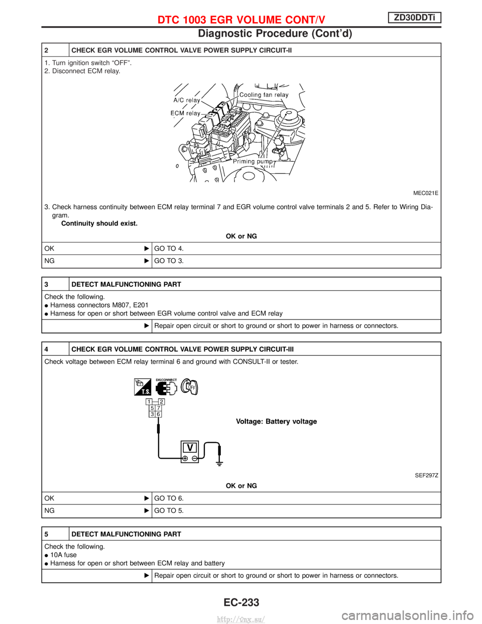
2 CHECK EGR VOLUME CONTROL VALVE POWER SUPPLY CIRCUIT-II
1. Turn ignition switch ªOFFº.
2. Disconnect ECM relay.
MEC021E
3. Check harness continuity between ECM relay terminal 7 and EGR volume control valve terminals 2 and 5. Refer to Wiring Dia-gram. Continuity should exist.
OK or NG
OK EGO TO 4.
NG EGO TO 3.
3 DETECT MALFUNCTIONING PART
Check the following.
IHarness connectors M807, E201
I Harness for open or short between EGR volume control valve and ECM relay
ERepair open circuit or short to ground or short to power in harness or connectors.
4 CHECK EGR VOLUME CONTROL VALVE POWER SUPPLY CIRCUIT-III
Check voltage between ECM relay terminal 6 and ground with CONSULT-II or tester.
SEF297Z
OK or NG
OK EGO TO 6.
NG EGO TO 5.
5 DETECT MALFUNCTIONING PART
Check the following.
I10A fuse
I Harness for open or short between ECM relay and battery
ERepair open circuit or short to ground or short to power in harness or connectors.
DTC 1003 EGR VOLUME CONT/VZD30DDTi
Diagnostic Procedure (Cont'd)
EC-233
http://vnx.su/
Page 509 of 1833
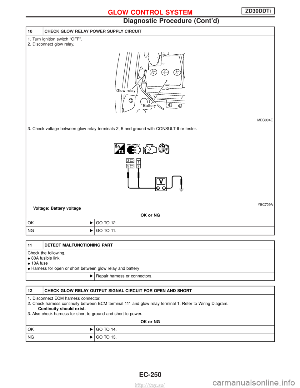
6 CHECK ECM RELAY
1. Apply 12V direct current between ECM relay terminals 1 and 2.
2. Check continuity between ECM relay terminals 3 and 5, 6 and 7.
SEF296X
OK or NG
OK EGO TO 7.
NG EReplace ECM relay.
7 CHECK EGR VOLUME CONTROL VALVE OUTPUT SIGNAL CIRCUIT FOR OPEN AND SHORT
1. Turn ignition switch ªOFFº.
2. Disconnect ECM harness connector.
3. Check harness continuity between ECM terminals and EGR volume control valve terminals as follows.
Refer to Wiring Diagram.
MTBL0442
Continuity should exist.
4. Also check harness for short to ground and short to power.
OK or NG
OK EGO TO 9.
NG EGO TO 8.
8 DETECT MALFUNCTIONING PART
Check the following.
IHarness connectors E225, F108
I Harness connectors F135, M842 (RHD models)
I Harness for open or short between EGR volume control valve and ECM
ERepair open circuit or short to ground or short to power in harness or connectors.
DTC 1003 EGR VOLUME CONT/VZD30DDTi
Diagnostic Procedure (Cont'd)
EC-234
http://vnx.su/
Page 517 of 1833
Diagnostic Procedure
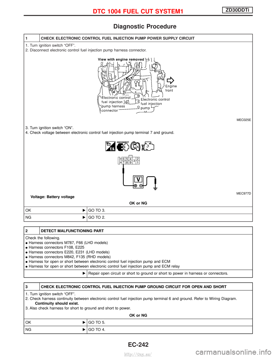
1 CHECK ELECTRONIC CONTROL FUEL INJECTION PUMP POWER SUPPLY CIRCUIT
1. Turn ignition switch ªOFFº.
2. Disconnect electronic control fuel injection pump harness connector.
MEC025E
3. Turn ignition switch ªONº.
4. Check voltage between electronic control fuel injection pump terminal 7 and ground.
MEC977DVoltage: Battery voltageOK or NG
OK EGO TO 3.
NG EGO TO 2.
2 DETECT MALFUNCTIONING PART
Check the following.
IHarness connectors M787, F66 (LHD models)
I Harness connectors F108, E225
I Harness connectors E220, E231 (LHD models)
I Harness connectors M842, F135 (RHD models)
I Harness for open or short between electronic control fuel injection pump and ECM
I Harness for open or short between electronic control fuel injection pump and ECM relay
ERepair open circuit or short to ground or short to power in harness or connectors.
3 CHECK ELECTRONIC CONTROL FUEL INJECTION PUMP GROUND CIRCUIT FOR OPEN AND SHORT
1. Turn ignition switch ªOFFº.
2. Check harness continuity between electronic control fuel injection pump terminal 6 and ground. Refer to Wiring Diagram.
Continuity should exist.
3. Also check harness for short to ground and short to power.
OK or NG
OK EGO TO 5.
NG EGO TO 4.
DTC 1004 FUEL CUT SYSTEM1ZD30DDTi
EC-242
http://vnx.su/
Page 524 of 1833
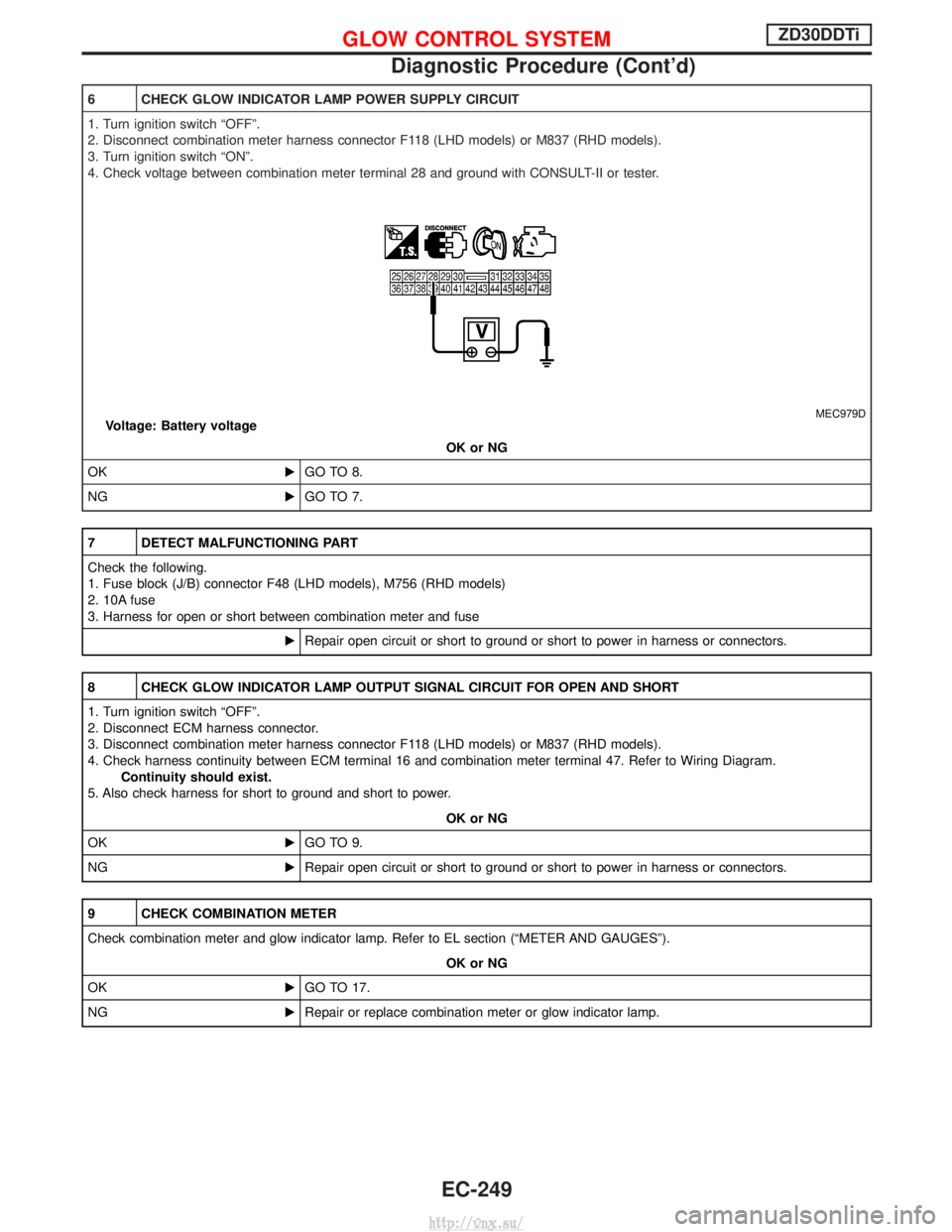
6 CHECK GLOW INDICATOR LAMP POWER SUPPLY CIRCUIT
1. Turn ignition switch ªOFFº.
2. Disconnect combination meter harness connector F118 (LHD models) or M837 (RHD models).
3. Turn ignition switch ªONº.
4. Check voltage between combination meter terminal 28 and ground with CONSULT-II or tester.
MEC979DVoltage: Battery voltageOK or NG
OK EGO TO 8.
NG EGO TO 7.
7 DETECT MALFUNCTIONING PART
Check the following.
1. Fuse block (J/B) connector F48 (LHD models), M756 (RHD models)
2. 10A fuse
3. Harness for open or short between combination meter and fuse
ERepair open circuit or short to ground or short to power in harness or connectors.
8 CHECK GLOW INDICATOR LAMP OUTPUT SIGNAL CIRCUIT FOR OPEN AND SHORT
1. Turn ignition switch ªOFFº.
2. Disconnect ECM harness connector.
3. Disconnect combination meter harness connector F118 (LHD models) or M837 (RHD models).
4. Check harness continuity between ECM terminal 16 and combination meter terminal 47. Refer to Wiring Diagram.
Continuity should exist.
5. Also check harness for short to ground and short to power.
OK or NG
OK EGO TO 9.
NG ERepair open circuit or short to ground or short to power in harness or connectors.
9 CHECK COMBINATION METER
Check combination meter and glow indicator lamp. Refer to EL section (ªMETER AND GAUGESº).
OK or NG
OK EGO TO 17.
NG ERepair or replace combination meter or glow indicator lamp.
GLOW CONTROL SYSTEMZD30DDTi
Diagnostic Procedure (Cont'd)
EC-249
http://vnx.su/
Page 525 of 1833
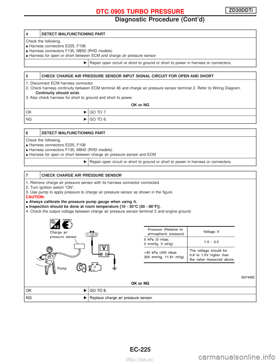
10 CHECK GLOW RELAY POWER SUPPLY CIRCUIT
1. Turn ignition switch ªOFFº.
2. Disconnect glow relay.
MEC004E
3. Check voltage between glow relay terminals 2, 5 and ground with CONSULT-II or tester.
YEC709AVoltage: Battery voltageOK or NG
OK EGO TO 12.
NG EGO TO 11.
11 DETECT MALFUNCTIONING PART
Check the following.
I80A fusible link
I 10A fuse
I Harness for open or short between glow relay and battery
ERepair harness or connectors.
12 CHECK GLOW RELAY OUTPUT SIGNAL CIRCUIT FOR OPEN AND SHORT
1. Disconnect ECM harness connector.
2. Check harness continuity between ECM terminal 111 and glow relay terminal 1. Refer to Wiring Diagram.
Continuity should exist.
3. Also check harness for short to ground and short to power.
OK or NG
OK EGO TO 14.
NG EGO TO 13.
GLOW CONTROL SYSTEMZD30DDTi
Diagnostic Procedure (Cont'd)
EC-250
http://vnx.su/
Page 529 of 1833
Diagnostic Procedure
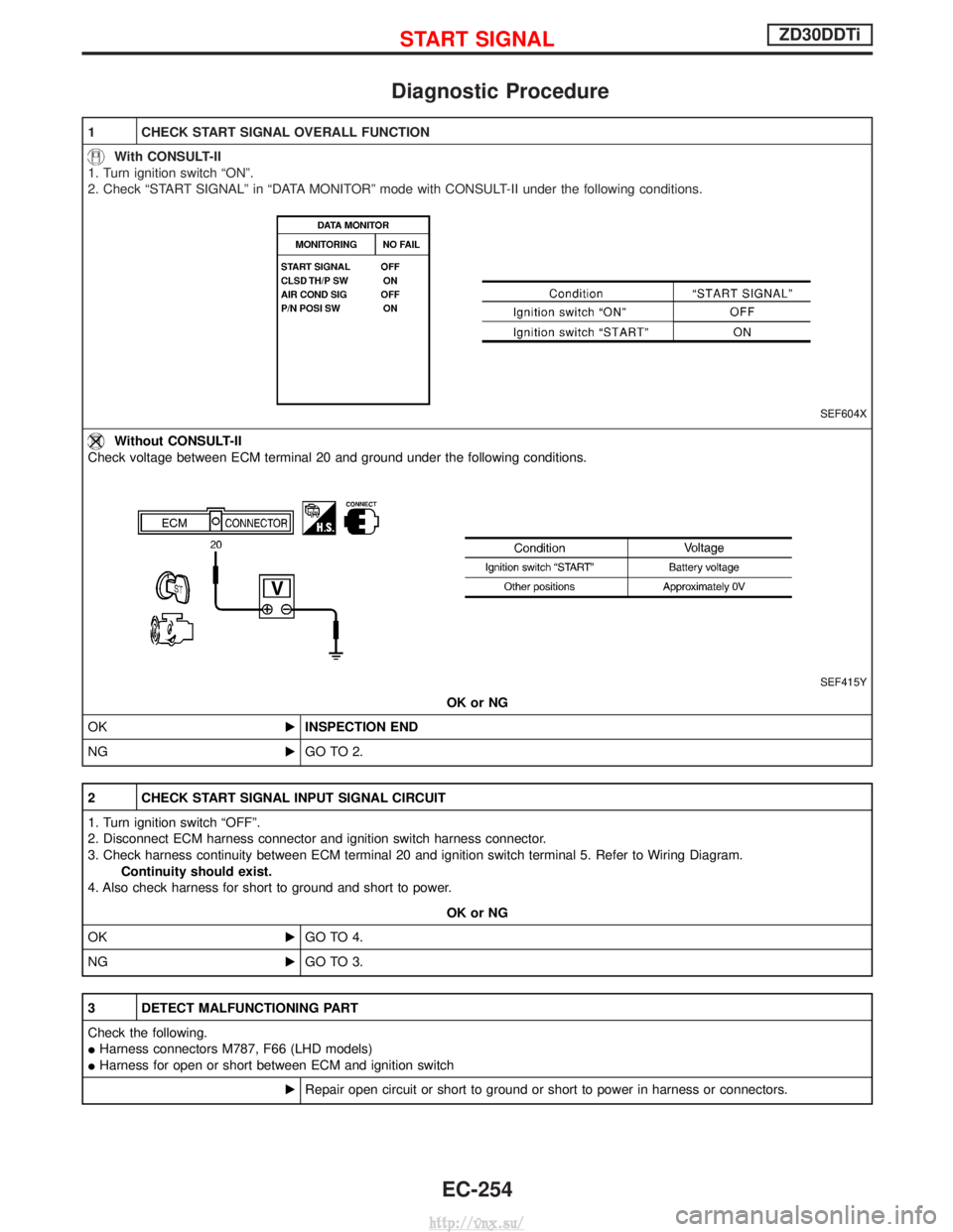
1 CHECK START SIGNAL OVERALL FUNCTION
With CONSULT-II
1. Turn ignition switch ªONº.
2. Check ªSTART SIGNALº in ªDATA MONITORº mode with CONSULT-II under the following conditions.
SEF604X
Without CONSULT-II
Check voltage between ECM terminal 20 and ground under the following conditions.
SEF415Y
OK or NG
OK EINSPECTION END
NG EGO TO 2.
2 CHECK START SIGNAL INPUT SIGNAL CIRCUIT
1. Turn ignition switch ªOFFº.
2. Disconnect ECM harness connector and ignition switch harness connector.
3. Check harness continuity between ECM terminal 20 and ignition switch terminal 5. Refer to Wiring Diagram.
Continuity should exist.
4. Also check harness for short to ground and short to power.
OK or NG
OK EGO TO 4.
NG EGO TO 3.
3 DETECT MALFUNCTIONING PART
Check the following.
IHarness connectors M787, F66 (LHD models)
I Harness for open or short between ECM and ignition switch
ERepair open circuit or short to ground or short to power in harness or connectors.
START SIGNALZD30DDTi
EC-254
http://vnx.su/
Page 534 of 1833
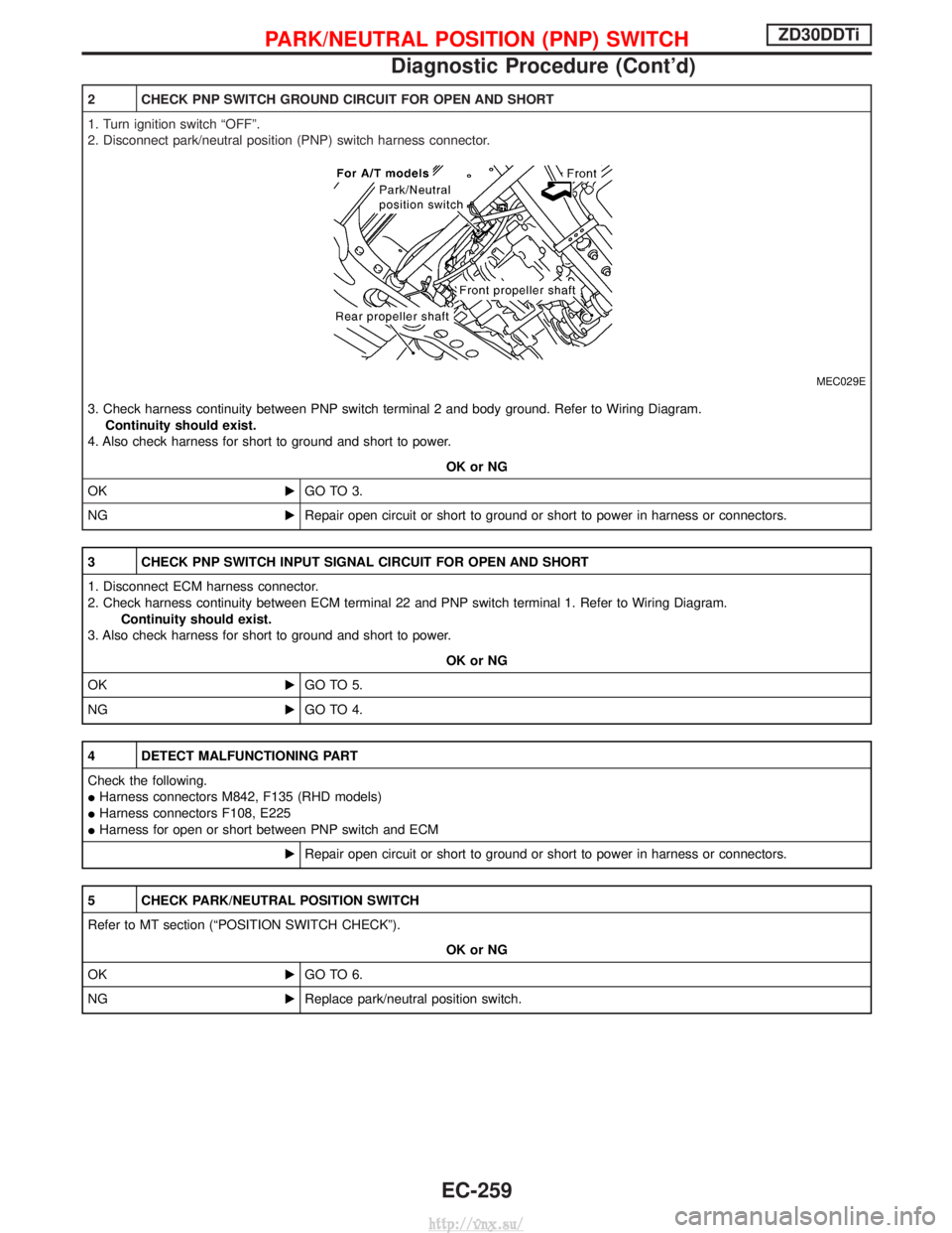
2 CHECK PNP SWITCH GROUND CIRCUIT FOR OPEN AND SHORT
1. Turn ignition switch ªOFFº.
2. Disconnect park/neutral position (PNP) switch harness connector.
MEC029E
3. Check harness continuity between PNP switch terminal 2 and body ground. Refer to Wiring Diagram.Continuity should exist.
4. Also check harness for short to ground and short to power.
OK or NG
OK EGO TO 3.
NG ERepair open circuit or short to ground or short to power in harness or connectors.
3 CHECK PNP SWITCH INPUT SIGNAL CIRCUIT FOR OPEN AND SHORT
1. Disconnect ECM harness connector.
2. Check harness continuity between ECM terminal 22 and PNP switch terminal 1. Refer to Wiring Diagram.
Continuity should exist.
3. Also check harness for short to ground and short to power.
OK or NG
OK EGO TO 5.
NG EGO TO 4.
4 DETECT MALFUNCTIONING PART
Check the following.
IHarness connectors M842, F135 (RHD models)
I Harness connectors F108, E225
I Harness for open or short between PNP switch and ECM
ERepair open circuit or short to ground or short to power in harness or connectors.
5 CHECK PARK/NEUTRAL POSITION SWITCH
Refer to MT section (ªPOSITION SWITCH CHECKº).
OK or NG
OK EGO TO 6.
NG EReplace park/neutral position switch.
PARK/NEUTRAL POSITION (PNP) SWITCHZD30DDTi
Diagnostic Procedure (Cont'd)
EC-259
http://vnx.su/