Page 1455 of 1833
qD
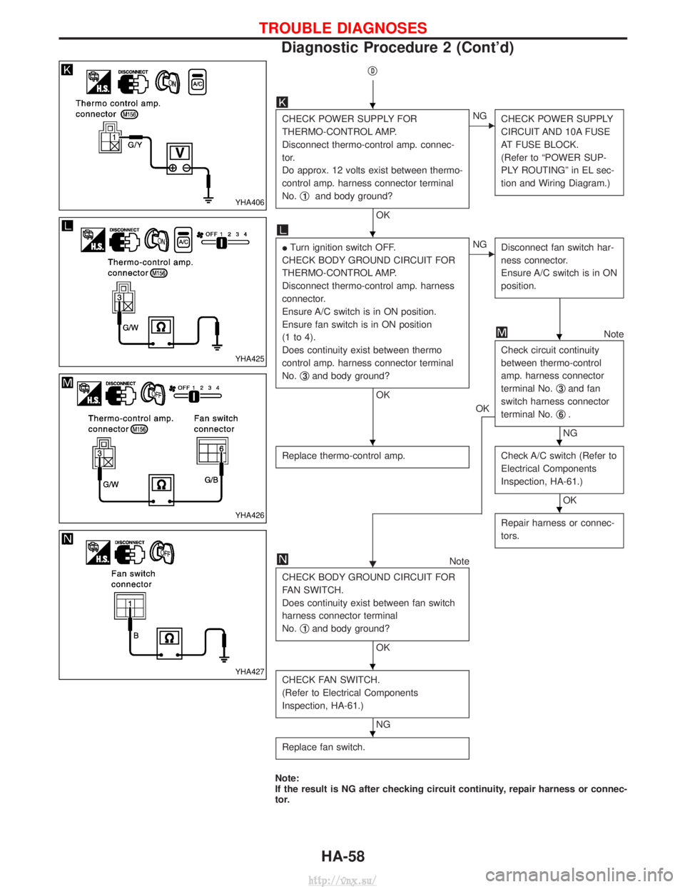
CHECK POWER SUPPLY FOR
THERMO-CONTROL AMP.
Disconnect thermo-control amp. connec-
tor.
Do approx. 12 volts exist between thermo-
control amp. harness connector terminal
No.q
1and body ground?
OK
ENG
CHECK POWER SUPPLY
CIRCUIT AND 10A FUSE
AT FUSE BLOCK.
(Refer to ªPOWER SUP-
PLY ROUTINGº in EL sec-
tion and Wiring Diagram.)
ITurn ignition switch OFF.
CHECK BODY GROUND CIRCUIT FOR
THERMO-CONTROL AMP.
Disconnect thermo-control amp. harness
connector.
Ensure A/C switch is in ON position.
Ensure fan switch is in ON position
(1 to 4).
Does continuity exist between thermo
control amp. harness connector terminal
No. q
3and body ground?
OK
ENG
Disconnect fan switch har-
ness connector.
Ensure A/C switch is in ON
position.
OK
Note
Check circuit continuity
between thermo-control
amp. harness connector
terminal No. q
3and fan
switch harness connector
terminal No. q
6.
NG
Replace thermo-control amp.
Check A/C switch (Refer to
Electrical Components
Inspection, HA-61.)
OK
H Repair harness or connec-
tors.Note
CHECK BODY GROUND CIRCUIT FOR
FAN SWITCH.
Does continuity exist between fan switch
harness connector terminal
No. q
1and body ground?
OK
CHECK FAN SWITCH.
(Refer to Electrical Components
Inspection, HA-61.)
NG
Replace fan switch.
Note:
If the result is NG after checking circuit continuity, repair harness or connec-
tor.
YHA406
YHA425
YHA426
YHA427
H
H
H
HH
H
H
H
TROUBLE DIAGNOSES
Diagnostic Procedure 2 (Cont'd)
HA-58
http://vnx.su/
Page 1457 of 1833
Diagnostic Procedure 3
SYMPTOM: Intake door does not change.
CHECK OPERATION
Does intake door motor (recirculation sys-
tem) operate, correctly?
NG
EOKIntake door motor (recir-
culation system) is OK.
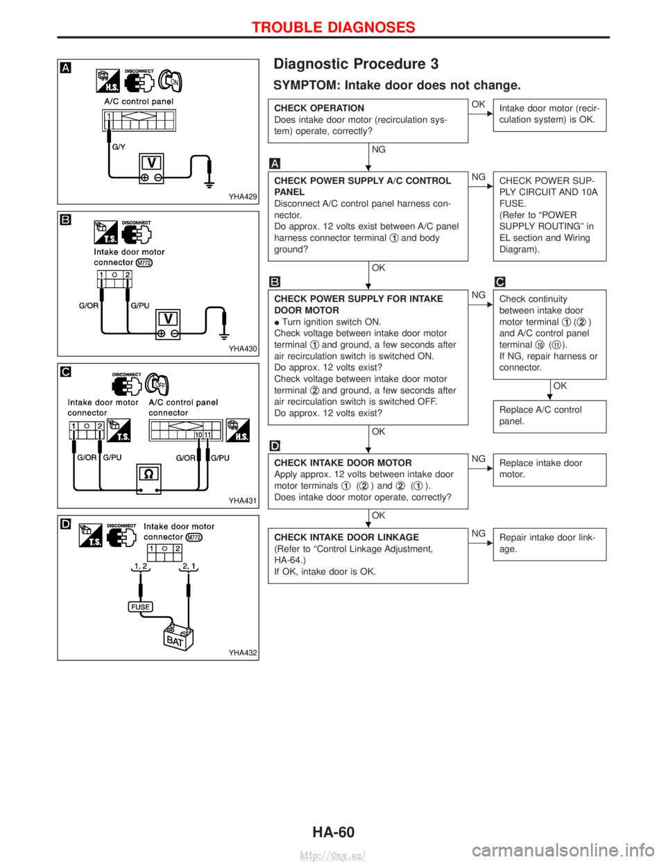
CHECK POWER SUPPLY A/C CONTROL
PANEL
Disconnect A/C control panel harness con-
nector.
Do approx. 12 volts exist between A/C panel
harness connector terminal q
1and body
ground?
OK
ENG CHECK POWER SUP-
PLY CIRCUIT AND 10A
FUSE.
(Refer to ªPOWER
SUPPLY ROUTINGº in
EL section and Wiring
Diagram).
CHECK POWER SUPPLY FOR INTAKE
DOOR MOTOR
ITurn ignition switch ON.
Check voltage between intake door motor
terminal q
1and ground, a few seconds after
air recirculation switch is switched ON.
Do approx. 12 volts exist?
Check voltage between intake door motor
terminal q
2and ground, a few seconds after
air recirculation switch is switched OFF.
Do approx. 12 volts exist?
OK
ENG Check continuity
between intake door
motor terminal q
1(q2)
and A/C control panel
terminal q
10(q11).
If NG, repair harness or
connector.
OK
Replace A/C control
panel.
CHECK INTAKE DOOR MOTOR
Apply approx. 12 volts between intake door
motor terminals q
1(q2) and q2(q1).
Does intake door motor operate, correctly?
OK
ENG Replace intake door
motor.
CHECK INTAKE DOOR LINKAGE
(Refer to ªControl Linkage Adjustment,
HA-64.)
If OK, intake door is OK.ENGRepair intake door link-
age.
YHA429
YHA430
YHA431
YHA432
H
H
H
H
H
TROUBLE DIAGNOSES
HA-60
http://vnx.su/
Page 1496 of 1833
WIRING DIAGRAM REFERENCE CHART
ENGINE CONTROL SYSTEM, IGNITION SYSTEM ........................................................................\
........................EC SECTION
RESTRAINT SYSTEM (AIR BAG) ........................................................................\
...................................................RS SECTION
HEATER AND AIR CONDITIONER ........................................................................\
..................................................HA SECTION
CONTENTS(Cont'd)
EL-3
http://vnx.su/
Page 1640 of 1833
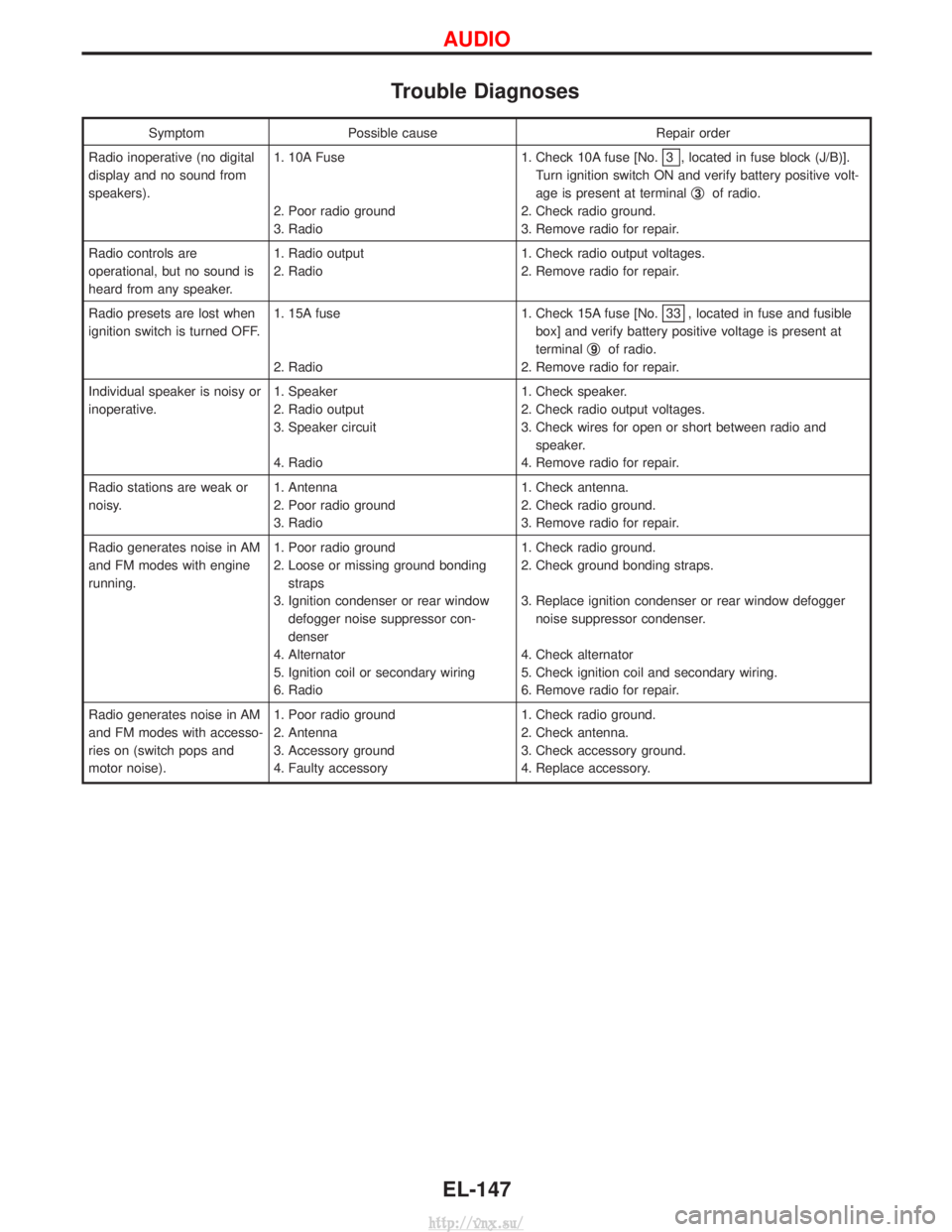
Trouble Diagnoses
SymptomPossible cause Repair order
Radio inoperative (no digital
display and no sound from
speakers). 1. 10A Fuse
2. Poor radio ground
3. Radio 1. Check 10A fuse [No.
3 , located in fuse block (J/B)].
Turn ignition switch ON and verify battery positive volt-
age is present at terminal q
3of radio.
2. Check radio ground.
3. Remove radio for repair.
Radio controls are
operational, but no sound is
heard from any speaker. 1. Radio output
2. Radio
1. Check radio output voltages.
2. Remove radio for repair.
Radio presets are lost when
ignition switch is turned OFF. 1. 15A fuse
2. Radio 1. Check 15A fuse [No.
33 , located in fuse and fusible
box] and verify battery positive voltage is present at
terminal q
9of radio.
2. Remove radio for repair.
Individual speaker is noisy or
inoperative. 1. Speaker
2. Radio output
3. Speaker circuit
4. Radio 1. Check speaker.
2. Check radio output voltages.
3. Check wires for open or short between radio and
speaker.
4. Remove radio for repair.
Radio stations are weak or
noisy. 1. Antenna
2. Poor radio ground
3. Radio 1. Check antenna.
2. Check radio ground.
3. Remove radio for repair.
Radio generates noise in AM
and FM modes with engine
running. 1. Poor radio ground
2. Loose or missing ground bonding
straps
3. Ignition condenser or rear window defogger noise suppressor con-
denser
4. Alternator
5. Ignition coil or secondary wiring
6. Radio 1. Check radio ground.
2. Check ground bonding straps.
3. Replace ignition condenser or rear window defogger
noise suppressor condenser.
4. Check alternator
5. Check ignition coil and secondary wiring.
6. Remove radio for repair.
Radio generates noise in AM
and FM modes with accesso-
ries on (switch pops and
motor noise). 1. Poor radio ground
2. Antenna
3. Accessory ground
4. Faulty accessory 1. Check radio ground.
2. Check antenna.
3. Check accessory ground.
4. Replace accessory.
AUDIO
EL-147
http://vnx.su/
