Page 403 of 1833

Diagnostic Procedure
1 CHECK ELECTRONIC CONTROL FUEL INJECTION PUMP POWER SUPPLY CIRCUIT
1. Turn ignition switch ªOFFº.
2. Disconnect electronic control fuel injection pump harness connector.
MEC025E
3. Turn ignition switch ªONº.
4. Check voltage between electronic control fuel injection pump terminal 7 and ground.
MEC977DVoltage: Battery voltageOK or NG
OK EGO TO 3.
NG EGO TO 2.
2 DETECT MALFUNCTIONING PART
Check the following.
IHarness connectors M787, F66 (LHD models)
I Harness connectors F108, E225
I Harness connectors E220, E231
I Harness connectors M842, F135 (RHD models)
I Harness for open or short between electronic control fuel injection pump and ECM
I Harness for open or short between electronic control fuel injection pump and ECM relay
ERepair open circuit or short to ground or short to power in harness or connectors.
3 CHECK ELECTRONIC CONTROL FUEL INJECTION PUMP GROUND CIRCUIT FOR OPEN AND SHORT
1. Turn ignition switch ªOFFº.
2. Check harness continuity between electronic control fuel injection pump terminal 6 and ground. Refer to Wiring Diagram.
Continuity should exist.
3. Also check harness for short to ground and short to power.
OK or NG
OK EGO TO 5.
NG EGO TO 4.
DTC 0402 P9×FUEL TEMP SENZD30DDTi
EC-128
http://vnx.su/
Page 415 of 1833

4 CHECK ACCELERATOR POSITION SENSOR GROUND CIRCUIT FOR OPEN AND SHORT
1. Turn ignition switch ªOFFº.
2. Loosen and retighten engine ground screw.
MEC994D
3. Check harness continuity between accelerator position sensor terminal 3 and engine ground. Refer to Wiring Diagram.Continuity should exist.
4. Also check harness for short to ground and short to power.
OK or NG
OK EGO TO 5.
NG ERepair open circuit or short to ground or short to power in harness or connectors.
5 CHECK ACCELERATOR POSITION SENSOR INPUT SIGNAL CIRCUIT FOR OPEN AND SHORT
1. Disconnect ECM harness connector.
2. Check harness continuity between ECM terminal 23 and accelerator position sensor terminal 2. Refer to Wiring Diagram.
Continuity should exist.
3. Also check harness for short to ground and short to power.
OK or NG
OK (with CONSULT-II) EGO TO 6.
OK (without CONSULT-II) EGO TO 7.
NG ERepair open circuit or short to ground or short to power in harness or connectors.
DTC 0403 ACCEL POS SENSORZD30DDTi
Diagnostic Procedure (Cont'd)
EC-140
http://vnx.su/
Page 418 of 1833

13 CHECK ACCELERATOR POSITION SWITCH INPUT SIGNAL CIRCUIT-I FOR OPEN AND SHORT
1. Turn ignition switch ªOFFº.
2. Disconnect ECM harness connector.
3. Check harness continuity between accelerator position switch terminal 6 and ECM terminal 31. Refer to Wiring Diagram.Continuity should exist.
4. Also check harness for short to ground and short to power.
OK or NG
OK EGO TO 14.
NG ERepair open circuit or short to ground or short to power in harness or connectors.
14 CHECK ACCELERATOR POSITION SWITCH INPUT SIGNAL CIRCUIT-II FOR OPEN AND SHORT
1. Check harness continuity between accelerator position switch terminal 4 and ECM terminal 32. Refer to Wiring Diagram.
Continuity should exist.
2. Also check harness for short to ground and short to power.
OK or NG
OK EGO TO 15.
NG ERepair open circuit or short to ground or short to power in harness or connectors.
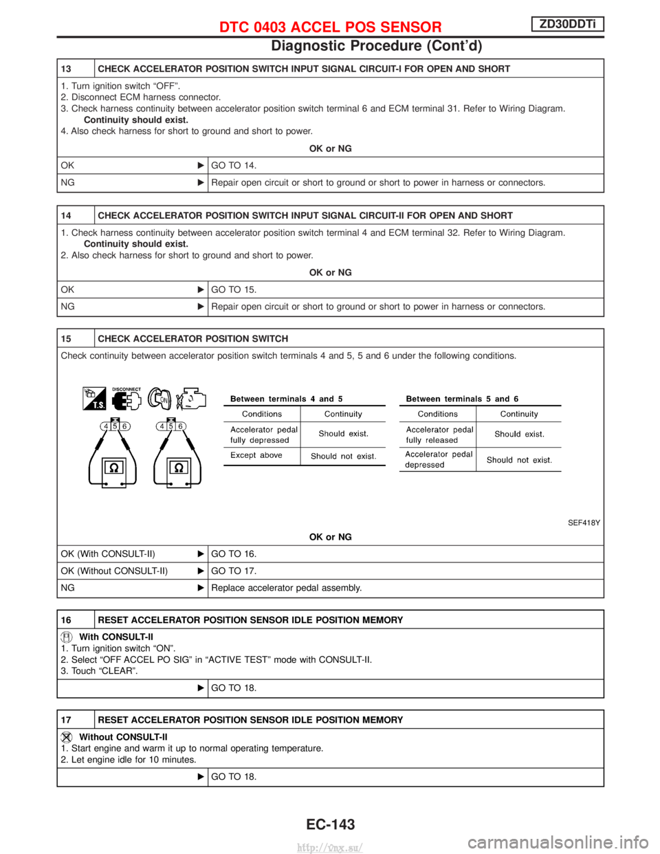
15 CHECK ACCELERATOR POSITION SWITCH
Check continuity between accelerator position switch terminals 4 and 5, 5 and 6 under the following conditions.
SEF418Y
OK or NG
OK (With CONSULT-II) EGO TO 16.
OK (Without CONSULT-II) EGO TO 17.
NG EReplace accelerator pedal assembly.
16 RESET ACCELERATOR POSITION SENSOR IDLE POSITION MEMORY
With CONSULT-II
1. Turn ignition switch ªONº.
2. Select ªOFF ACCEL PO SIGº in ªACTIVE TESTº mode with CONSULT-II.
3. Touch ªCLEARº.
EGO TO 18.
17 RESET ACCELERATOR POSITION SENSOR IDLE POSITION MEMORY
Without CONSULT-II
1. Start engine and warm it up to normal operating temperature.
2. Let engine idle for 10 minutes.
EGO TO 18.
DTC 0403 ACCEL POS SENSORZD30DDTi
Diagnostic Procedure (Cont'd)
EC-143
http://vnx.su/
Page 421 of 1833
3 CHECK ACCELERATOR POSITION SENSOR POWER SUPPLY CIRCUIT
1. Turn ignition switch ªOFFº.
2. Disconnect accelerator work unit harness connector.
3. Turn ignition switch ªONº.
4. Check voltage between accelerator work unit terminal 2 and ground with CONSULT-II or tester.
YEC706A
OK or NG
OK EGO TO 4.
NG ERepair open circuit or short to ground or short to power in harness or connectors.
4 CHECK ACCELERATOR POSITION SENSOR GROUND CIRCUIT FOR OPEN AND SHORT
1. Turn ignition switch ªOFFº.
2. Loosen and retighten engine ground screw.
MEC994D
3. Check harness continuity between accelerator work unit terminal 3 and engine ground. Refer to Wiring Diagram.
Continuity should exist.
4. Also check harness for short to ground and short to power.
OK or NG
OK EGO TO 5.
NG ERepair open circuit or short to ground or short to power in harness or connectors.
DTC 0403 ACCEL POS SENSORZD30DDTi
Diagnostic Procedure (Cont'd)
EC-146
http://vnx.su/
Page 422 of 1833

5 CHECK ACCELERATOR POSITION SENSOR INPUT SIGNAL CIRCUIT FOR OPEN AND SHORT
1. Disconnect ECM harness connector.
2. Check harness continuity between ECM terminal 23 and accelerator work unit terminal 4. Refer to Wiring Diagram.Continuity should exist.
3. Also check harness for short to ground and short to power.
OK or NG
OK (with CONSULT-II) EGO TO 6.
OK (without CONSULT-II) EGO TO 7.
NG ERepair open circuit or short to ground or short to power in harness or connectors.
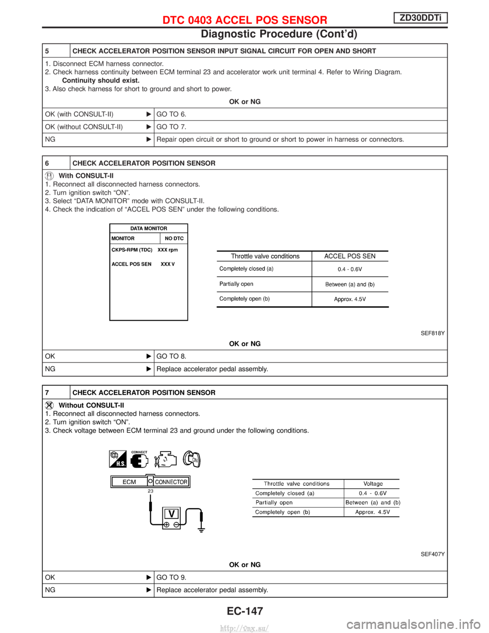
6 CHECK ACCELERATOR POSITION SENSOR
With CONSULT-II
1. Reconnect all disconnected harness connectors.
2. Turn ignition switch ªONº.
3. Select ªDATA MONITORº mode with CONSULT-II.
4. Check the indication of ªACCEL POS SENº under the following conditions.
SEF818Y
OK or NG
OK EGO TO 8.
NG EReplace accelerator pedal assembly.
7 CHECK ACCELERATOR POSITION SENSOR
Without CONSULT-II
1. Reconnect all disconnected harness connectors.
2. Turn ignition switch ªONº.
3. Check voltage between ECM terminal 23 and ground under the following conditions.
SEF407Y
OK or NG
OK EGO TO 9.
NG EReplace accelerator pedal assembly.
DTC 0403 ACCEL POS SENSORZD30DDTi
Diagnostic Procedure (Cont'd)
EC-147
http://vnx.su/
Page 424 of 1833

13 CHECK ACCELERATOR POSITION SWITCH INPUT SIGNAL CIRCUIT FOR OPEN AND SHORT
1. Turn ignition switch ªOFFº.
2. Disconnect ECM harness connector.
3. Check harness continuity between accelerator work unit terminal 5 and ECM terminal 31. Refer to Wiring Diagram.Continuity should exist.
4. Also check harness for short to ground and short to power.
OK or NG
OK EGO TO 14.
NG ERepair open circuit or short to ground or short to power in harness or connectors.
14 CHECK ACCELERATOR POSITION SWITCH
Check continuity between accelerator work unit terminals 5 and 6 under the following conditions.
YEC708A
OK or NG
OK (With CONSULT-II) EGO TO 15.
OK (Without CONSULT-II) EGO TO 16.
NG EReplace accelerator pedal assembly.
15 RESET ACCELERATOR POSITION SENSOR IDLE POSITION MEMORY
With CONSULT-II
1. Turn ignition switch ªONº.
2. Select ªOFF ACCEL PO SIGº in ªACTIVE TESTº mode with CONSULT-II.
3. Touch ªCLEARº.
EGO TO 18.
16 RESET ACCELERATOR POSITION SENSOR IDLE POSITION MEMORY
Without CONSULT-II
1. Start engine and warm it up to normal operating temperature.
2. Let engine idle for 10 minutes.
EGO TO 18.
17 CHECK INTERMITTENT INCIDENT
Refer to ªTROUBLE DIAGNOSIS FOR INTERMITTENT INCIDENTº, EC-78.
EINSPECTION END
DTC 0403 ACCEL POS SENSORZD30DDTi
Diagnostic Procedure (Cont'd)
EC-149
http://vnx.su/
Page 431 of 1833
Diagnostic Procedure
1 CHECK CRANKSHAFT POSITION SENSOR (TDC) GROUND CIRCUIT FOR OPEN AND SHORT
1. Turn ignition switch ªOFFº.
2. Loosen and retighten engine ground screws.
MEC994D
3. Disconnect crankshaft position sensor (TDC) harness connector and ECM harness connector.
MEC998D
MEC018E
4. Check harness continuity between ECM terminal 47 and terminal 2. Refer to Wiring Diagram.Continuity should exist.
5. Also check harness for short to ground and short to power.
OK or NG
OK EGO TO 3.
NG EGO TO 2.
DTC 0407 CRANK POS SEN (TDC)ZD30DDTi
EC-156
http://vnx.su/
Page 439 of 1833
Diagnostic Procedure
1 CHECK INPUT SIGNAL CIRCUIT
1. Turn ignition switch ªOFFº.
2. Disconnect ECM harness connector and TCM (Transmission control module) harness connector.
MEC020E
MEC026E
3. Check harness continuity between the following terminals. Refer to Wiring Diagram.
MTBL0532
Continuity should exist.OK or NG
OK EGO TO 3.
NG EGO TO 2.
2 DETECT MALFUNCTIONING PART
Check the following.
IHarness connectors M788, F93 (LHD models)
I Harness for open or short between ECM and TCM (Transmission control module)
ERepair harness or connectors.
DTC 0504 A/T COMM LINEZD30DDTi
EC-164
http://vnx.su/