Page 215 of 1833
WARNING:
a. Situate vehicle on a flat and solid surface.
b. Place chocks at front and back of rear wheels.
c. Do not remove engine until exhaust system has completelycooled off.
d. For safety during subsequent steps, the tension of wires should be slackened against the engine.
e. Be sure to hoist engine in a safe manner.
f. For engines not equipped with engine slingers, attach proper slingers and bolts described in PARTS CATALOG.
CAUTION:
I When lifting engine, be careful not to strike adjacent parts,
especially, brake lines and brake master cylinder.
I In hoisting the engine, always use engine slingers in a safe
manner.
ENGINE REMOVALTD27Ti
EM-124
http://vnx.su/
Page 776 of 1833
INSTALLATION
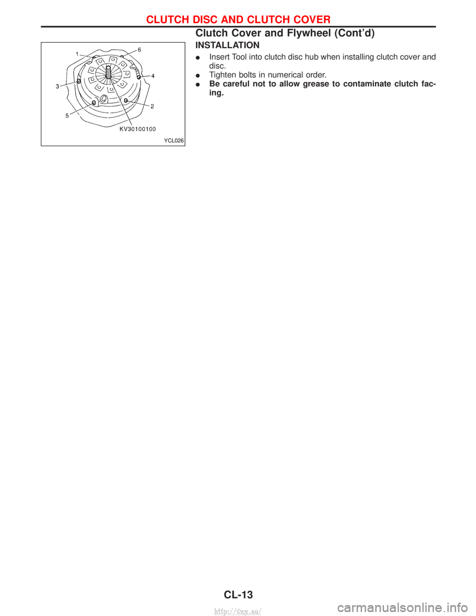
IInsert Tool into clutch disc hub when installing clutch cover and
disc.
I Tighten bolts in numerical order.
I Be careful not to allow grease to contaminate clutch fac-
ing.
YCL026
CLUTCH DISC AND CLUTCH COVER
Clutch Cover and Flywheel (Cont'd)
CL-13
http://vnx.su/
Page 1116 of 1833
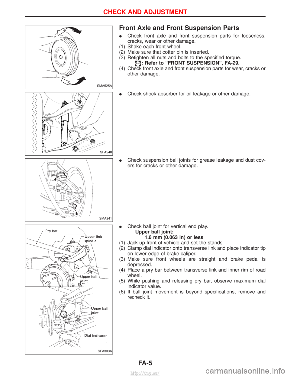
Front Axle and Front Suspension Parts
ICheck front axle and front suspension parts for looseness,
cracks, wear or other damage.
(1) Shake each front wheel.
(2) Make sure that cotter pin is inserted.
(3) Retighten all nuts and bolts to the specified torque.
: Refer to ªFRONT SUSPENSIONº, FA-29.
(4) Check front axle and front suspension parts for wear, cracks or other damage.
I Check shock absorber for oil leakage or other damage.
I Check suspension ball joints for grease leakage and dust cov-
ers for cracks or other damage.
I Check ball joint for vertical end play.
Upper ball joint: 1.6 mm (0.063 in) or less
(1) Jack up front of vehicle and set the stands.
(2) Clamp dial indicator onto transverse link and place indicator tip on lower edge of brake caliper.
(3) Make sure front wheels are straight and brake pedal is depressed.
(4) Place a pry bar between transverse link and inner rim of road wheel.
(5) While pushing and releasing pry bar, observe maximum dial indicator value.
(6) If ball joint movement is beyond specifications, remove and recheck it.
SMA525A
SFA240
SMA241
SFA303A
CHECK AND ADJUSTMENT
FA-5
http://vnx.su/
Page 1122 of 1833
TOE-IN
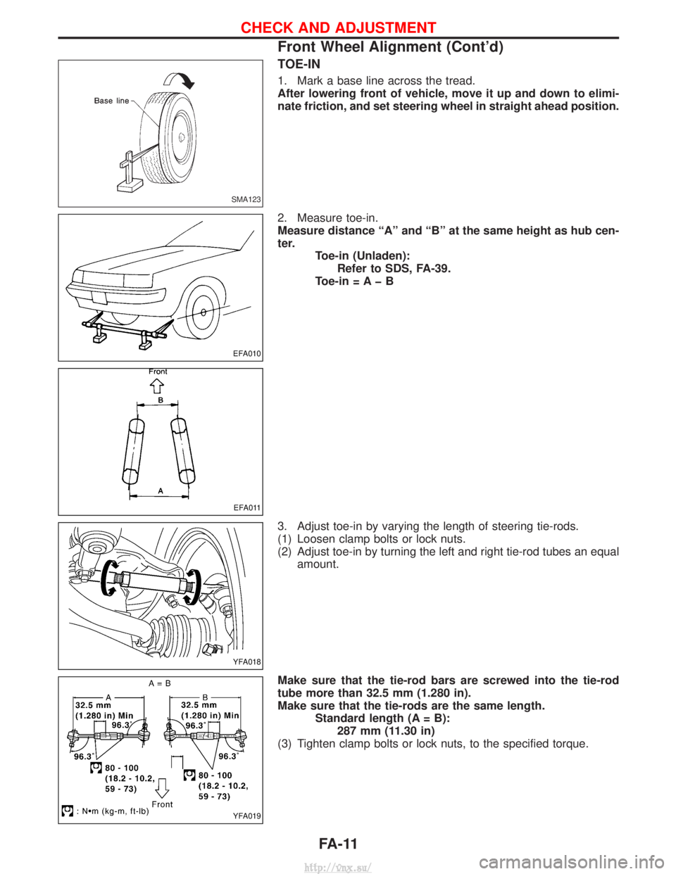
1. Mark a base line across the tread.
After lowering front of vehicle, move it up and down to elimi-
nate friction, and set steering wheel in straight ahead position.
2. Measure toe-in.
Measure distance ªAº and ªBº at the same height as hub cen-
ter.Toe-in (Unladen):Refer to SDS, FA-39.
Toe-in = A þ B
3. Adjust toe-in by varying the length of steering tie-rods.
(1) Loosen clamp bolts or lock nuts.
(2) Adjust toe-in by turning the left and right tie-rod tubes an equal amount.
Make sure that the tie-rod bars are screwed into the tie-rod
tube more than 32.5 mm (1.280 in).
Make sure that the tie-rods are the same length. Standard length (A = B):287 mm (11.30 in)
(3) Tighten clamp bolts or lock nuts, to the specified torque.
SMA123
EFA010
EFA011
YFA018
YFA019
CHECK AND ADJUSTMENT
Front Wheel Alignment (Cont'd)
FA-11
http://vnx.su/
Page 1144 of 1833
(3) If height of the vehicle is not as specified, adjust vehicle pos-ture.(Refer to SDS, FA-39.)
(4) Check wheel alignment if necessary. (Refer to SDS, FA-39.)
9. If ªHº dimension is not within the specified value, readjust vehicle posture using anchor arm adjusting nut.
Stabilizer Bar
REMOVAL
IRemove stabilizer bar ball joint nuts and clamp bolts.
INSPECTION
ICheck stabilizer bar for twist and deformation.
Replace if necessary.
I Check rubber bushing for cracks, wear or deterioration.
Replace if necessary.
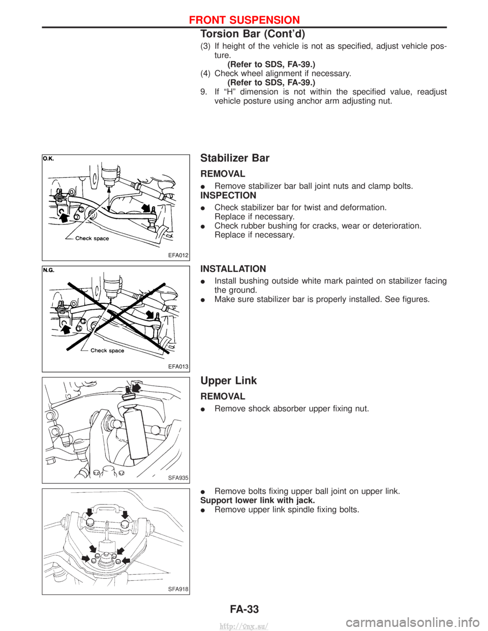
INSTALLATION
IInstall bushing outside white mark painted on stabilizer facing
the ground.
I Make sure stabilizer bar is properly installed. See figures.
Upper Link
REMOVAL
IRemove shock absorber upper fixing nut.
I Remove bolts fixing upper ball joint on upper link.
Support lower link with jack.
I Remove upper link spindle fixing bolts.
EFA012
EFA013
SFA935
SFA918
FRONT SUSPENSION
Torsion Bar (Cont'd)
FA-33
http://vnx.su/
Page 1156 of 1833
Rear Axle and Rear Suspension Parts
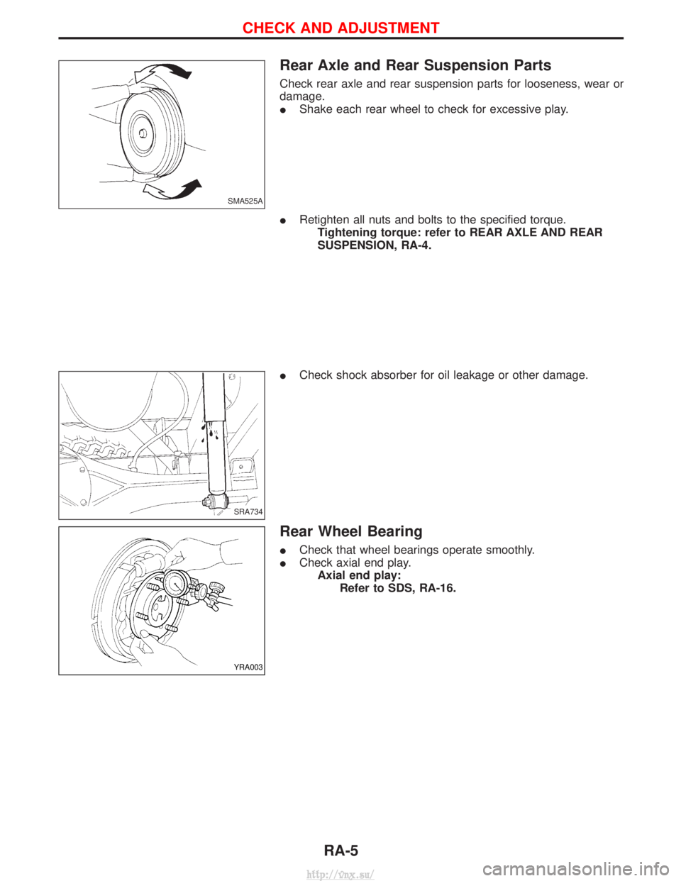
Check rear axle and rear suspension parts for looseness, wear or
damage.
IShake each rear wheel to check for excessive play.
I Retighten all nuts and bolts to the specified torque.
Tightening torque: refer to REAR AXLE AND REAR
SUSPENSION, RA-4.
I Check shock absorber for oil leakage or other damage.
Rear Wheel Bearing
ICheck that wheel bearings operate smoothly.
I Check axial end play.
Axial end play: Refer to SDS, RA-16.
SMA525A
SRA734
YRA003
CHECK AND ADJUSTMENT
RA-5
http://vnx.su/
Page 1195 of 1833
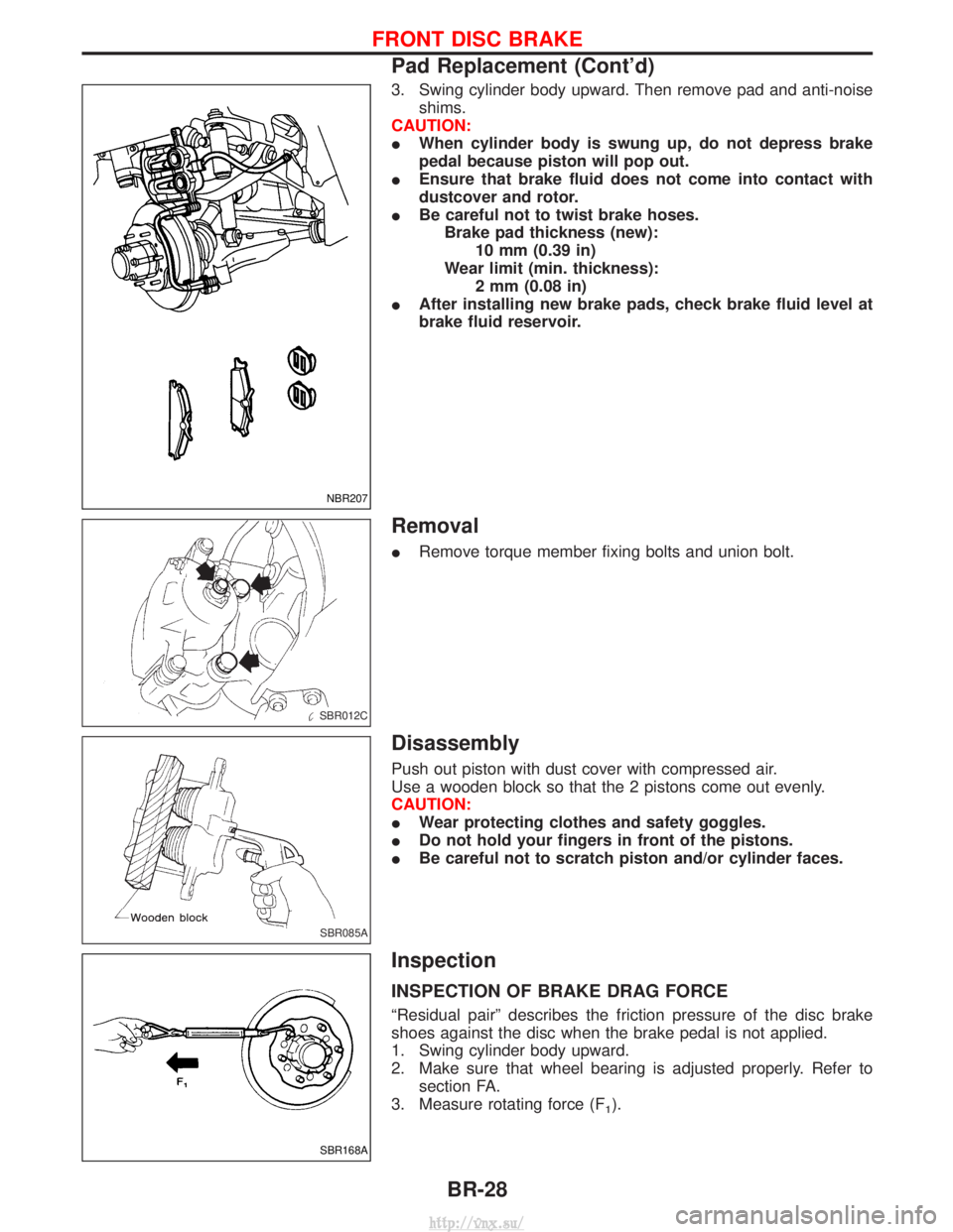
3. Swing cylinder body upward. Then remove pad and anti-noiseshims.
CAUTION:
I When cylinder body is swung up, do not depress brake
pedal because piston will pop out.
I Ensure that brake fluid does not come into contact with
dustcover and rotor.
I Be careful not to twist brake hoses.
Brake pad thickness (new): 10 mm (0.39 in)
Wear limit (min. thickness): 2 mm (0.08 in)
I After installing new brake pads, check brake fluid level at
brake fluid reservoir.
Removal
IRemove torque member fixing bolts and union bolt.
Disassembly
Push out piston with dust cover with compressed air.
Use a wooden block so that the 2 pistons come out evenly.
CAUTION:
IWear protecting clothes and safety goggles.
I Do not hold your fingers in front of the pistons.
I Be careful not to scratch piston and/or cylinder faces.
Inspection
INSPECTION OF BRAKE DRAG FORCE
ªResidual pairº describes the friction pressure of the disc brake
shoes against the disc when the brake pedal is not applied.
1. Swing cylinder body upward.
2. Make sure that wheel bearing is adjusted properly. Refer to
section FA.
3. Measure rotating force (F
1).
NBR207
SBR012C
SBR085A
SBR168A
FRONT DISC BRAKE
Pad Replacement (Cont'd)
BR-28
http://vnx.su/
Page 1262 of 1833
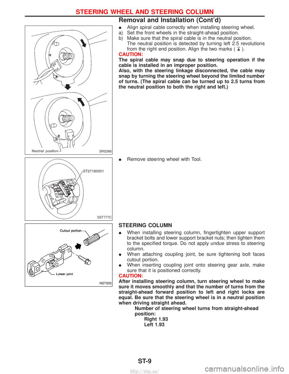
IAlign spiral cable correctly when installing steering wheel.
a) Set the front wheels in the straight-ahead position.
b) Make sure that the spiral cable is in the neutral position. The neutral position is detected by turning left 2.5 revolutions
from the right end position. Align the two marks (
).
CAUTION:
The spiral cable may snap due to steering operation if the
cable is installed in an improper position.
Also, with the steering linkage disconnected, the cable may
snap by turning the steering wheel beyond the limited number
of turns. (The spiral cable can be turned up to 2.5 turns from
the neutral position to both the right and left.)
I Remove steering wheel with Tool.
STEERING COLUMN
IWhen installing steering column, fingertighten upper support
bracket bolts and lower support bracket nuts; then tighten them
to the specified torque. Do not apply undue stress to steering
column.
I When attaching coupling joint, be sure tightening bolt faces
cutout portion.
I When inserting coupling joint onto steering gear axle, make
sure that it is positioned correctly.
CAUTION:
After installing steering column, turn steering wheel to make
sure it moves smoothly and that the number of turns from the
straight-ahead forward position to left and right locks are
equal. Be sure that the steering wheel is in a neutral position
when driving straight ahead. Number of steering wheel turns from straight-ahead
position:Right 1.93
Left 1.93
SRS266
SST777C
NST005
STEERING WHEEL AND STEERING COLUMN
Removal and Installation (Cont'd)
ST-9
http://vnx.su/