2004 NISSAN TERRANO wheel bolts
[x] Cancel search: wheel boltsPage 1277 of 1833
Precautions
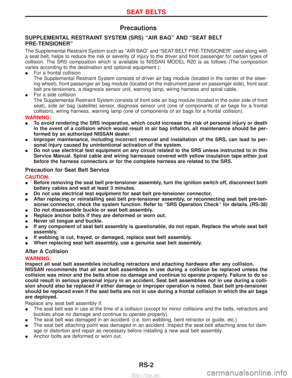
SUPPLEMENTAL RESTRAINT SYSTEM (SRS) ªAIR BAGº AND ªSEAT BELT
PRE-TENSIONERº
The Supplemental Restraint System such as ªAIR BAGº and ªSEAT BELT PRE-TENSIONERº used along with
a seat belt, helps to reduce the risk or severity of injury to the driver and front passenger for certain types of
collision. The SRS composition which is available to NISSAN MODEL R20 is as follows (The composition
varies according to the destination and optional equipment.):
IFor a frontal collision
The Supplemental Restraint System consists of driver air bag module (located in the center of the steer-
ing wheel), front passenger air bag module (located on the instrument panel on passenger side), front seat
belt pre-tensioners, a diagnosis sensor unit, warning lamp, wiring harness and spiral cable.
I For a side collision
The Supplemental Restraint System consists of front side air bag module (located in the outer side of front
seat), side air bag (satellite) sensor, diagnosis sensor unit (one of components of air bags for a frontal
collision), wiring harness, warning lamp (one of components of air bags for a frontal collision).
WARNING:
I To avoid rendering the SRS inoperative, which could increase the risk of personal injury or death
in the event of a collision which would result in air bag inflation, all maintenance should be per-
formed by an authorized NISSAN dealer.
I Improper maintenance, including incorrect removal and installation of the SRS, can lead to per-
sonal injury caused by unintentional activation of the system.
I Do not use electrical test equipment on any circuit related to the SRS unless instructed to in this
Service Manual. Spiral cable and wiring harnesses covered with yellow insulation tape either just
before the harness connectors or for the complete harness are related to the SRS.
Precaution for Seat Belt Service
CAUTION:
IBefore removing the seat belt pre-tensioner assembly, turn the ignition switch off, disconnect both
battery cables and wait at least 3 minutes.
I Do not use electrical test equipment for seat belt pre-tensioner connector.
I After replacing or reinstalling seat belt pre-tensioner assembly, or reconnecting seat belt pre-ten-
sioner connector, check the system function. Refer to ªSRS Operation Checkº for details. (RS-38)
I Do not disassemble buckle or seat belt assembly.
I Replace anchor bolts if they are deformed or worn out.
I Never oil tongue and buckle.
I If any component of seat belt assembly is questionable, do not repair. Replace the whole seat belt
assembly.
I If webbing is cut, frayed, or damaged, replace seat belt assembly.
I When replacing seat belt assembly, use a genuine seat belt assembly.
After A Collision
WARNING:
Inspect all seat belt assemblies including retractors and attaching hardware after any collision.
NISSAN recommends that all seat belt assemblies in use during a collision be replaced unless the
collision was minor and the belts show no damage and continue to operate properly. Failure to do so
could result in serious personal injury in an accident. Seat belt assemblies not in use during a colli-
sion should also be replaced if either damage or improper operation is noted. Seat belt pre-tensioner
should be replaced even if the seat belts are not in use during a frontal collision in which the air bags
are deployed.
Replace any seat belt assembly if:
IThe seat belt was in use at the time of a collision (except for minor collisions and the belts, retractors and
buckles show no damage and continue to operate properly).
I The seat belt was damaged in an accident. (i.e. torn webbing, bent retractor or guide, etc.)
I The seat belt attaching point was damaged in an accident. Inspect the seat belt attaching area for dam-
age or distortion and repair as necessary before installing a new seat belt assembly.
I Anchor bolts are deformed or worn out.
SEAT BELTS
RS-2
http://vnx.su/
Page 1288 of 1833
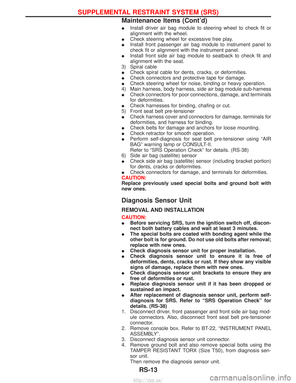
IInstall driver air bag module to steering wheel to check fit or
alignment with the wheel.
I Check steering wheel for excessive free play.
I Install front passenger air bag module to instrument panel to
check fit or alignment with the instrument panel.
I Install front side air bag module to seatback to check fit and
alignment with the seat.
3) Spiral cable
I Check spiral cable for dents, cracks, or deformities.
I Check connectors and protective tape for damage.
I Check steering wheel for noise, binding or heavy operation.
4) Main harness, body harness, side air bag module sub-harness
I Check connectors for poor connections, damage, and terminals
for deformities.
I Check harnesses for binding, chafing or cut.
5) Front seat belt pre-tensioner
I Check harness cover and connectors for damage, terminals for
deformities, and harness for binding.
I Check belts for damage and anchors for loose mounting.
I Check retractor for smooth operation.
I Perform self-diagnosis for seat belt pre-tensioner using ªAIR
BAGº warning lamp or CONSULT-II.
Refer to ªSRS Operation Checkº for details. (RS-38)
6) Side air bag (satellite) sensor
I Check side air bag (satellite) sensor (including bracket portion)
for dents, cracks or deformities.
I Check connectors for damage, and terminals for deformities.
CAUTION:
Replace previously used special bolts and ground bolt with
new ones.
Diagnosis Sensor Unit
REMOVAL AND INSTALLATION
CAUTION:
I Before servicing SRS, turn the ignition switch off, discon-
nect both battery cables and wait at least 3 minutes.
I The special bolts are coated with bonding agent while the
other bolt is for ground. Do not use old bolts after removal;
replace with new ones.
I Check diagnosis sensor unit for proper installation.
I Check diagnosis sensor unit to ensure it is free of
deformities, dents, cracks or rust. If they show any visible
signs of damage, replace them with new ones.
I Check diagnosis sensor unit brackets to ensure they are
free of deformities or rust.
I Replace diagnosis sensor unit if it has been dropped or
sustained an impact.
I After replacement of diagnosis sensor unit, perform self-
diagnosis for SRS. Refer to ªSRS Operation Checkº for
details. (RS-38)
1. Disconnect driver, front passenger and front side air bag mod- ule connectors. Also, disconnect front seat belt pre-tensioner
connector.
2. Remove console box. Refer to BT-22, ªINSTRUMENT PANEL ASSEMBLYº.
3. Disconnect diagnosis sensor unit connector.
4. Remove ground bolt and also remove special bolts using the TAMPER RESISTANT TORX (Size T50), from diagnosis sen-
sor unit.
Then remove the diagnosis sensor unit.
SUPPLEMENTAL RESTRAINT SYSTEM (SRS)
Maintenance Items (Cont'd)
RS-13
http://vnx.su/
Page 1294 of 1833
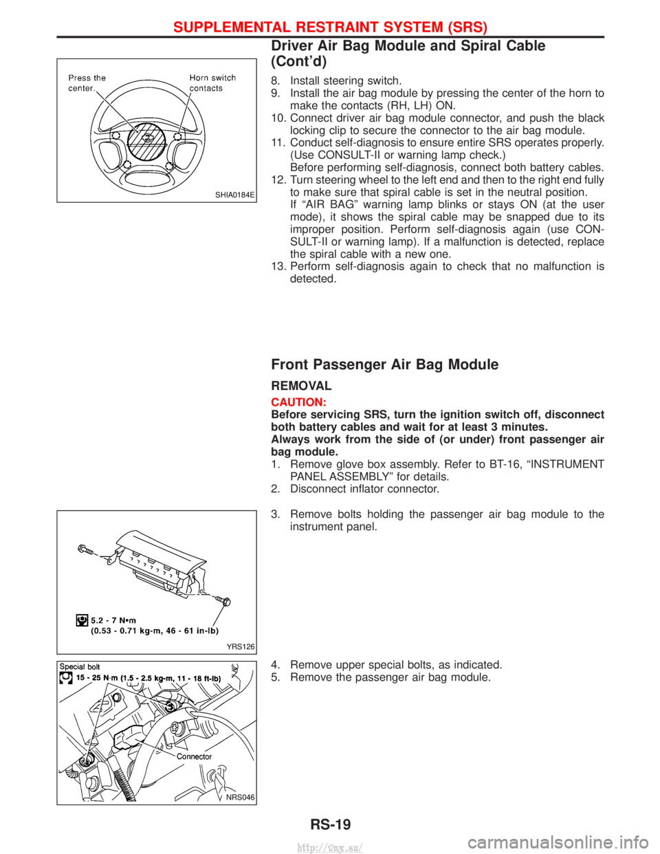
8. Install steering switch.
9. Install the air bag module by pressing the center of the horn tomake the contacts (RH, LH) ON.
10. Connect driver air bag module connector, and push the black locking clip to secure the connector to the air bag module.
11. Conduct self-diagnosis to ensure entire SRS operates properly. (Use CONSULT-II or warning lamp check.)
Before performing self-diagnosis, connect both battery cables.
12. Turn steering wheel to the left end and then to the right end fully to make sure that spiral cable is set in the neutral position.
If ªAIR BAGº warning lamp blinks or stays ON (at the user
mode), it shows the spiral cable may be snapped due to its
improper position. Perform self-diagnosis again (use CON-
SULT-II or warning lamp). If a malfunction is detected, replace
the spiral cable with a new one.
13. Perform self-diagnosis again to check that no malfunction is detected.
Front Passenger Air Bag Module
REMOVAL
CAUTION:
Before servicing SRS, turn the ignition switch off, disconnect
both battery cables and wait for at least 3 minutes.
Always work from the side of (or under) front passenger air
bag module.
1. Remove glove box assembly. Refer to BT-16, ªINSTRUMENTPANEL ASSEMBLYº for details.
2. Disconnect inflator connector.
3. Remove bolts holding the passenger air bag module to the instrument panel.
4. Remove upper special bolts, as indicated.
5. Remove the passenger air bag module.
SHIA0184E
YRS126
NRS046
SUPPLEMENTAL RESTRAINT SYSTEM (SRS)
Driver Air Bag Module and Spiral Cable
(Cont'd)
RS-19
http://vnx.su/
Page 1334 of 1833
Collision Diagnosis
FOR FRONTAL COLLISION
To repair the SRS, perform the following steps.
When SRS (except the side air bag modules) is activated in a collision:
1) Replace the diagnosis sensor unit.
2) Remove the air bag modules (except the side air bag modules) and front seat belt pre-tensioner assem-blies.
3) Check the SRS components using the table shown below:
I Replace any SRS components showing visible signs of damage (dents, cracks and deformation).
4) Install new air bag modules (except the side air bag module) and front seat belt pre-tensioner assemblies.
5) Conduct self-diagnosis using CONSULT-II or ªAIR BAGº warning lamp. Refer to ªSRS Operation Checkº for details (RS-38). Ensure entire SRS operation properly.
When SRS is not activated in a collision:
1) Check the SRS components using the table shown below:
I Replace any SRS components showing visible signs of damage (dents, cracks and deformation).
2) Conduct self-diagnosis using CONSULT-II or ªAIR BAGº warning lamp. Refer to ªSRS Operation Checkº for details (RS-38). Ensure entire SRS operation properly.
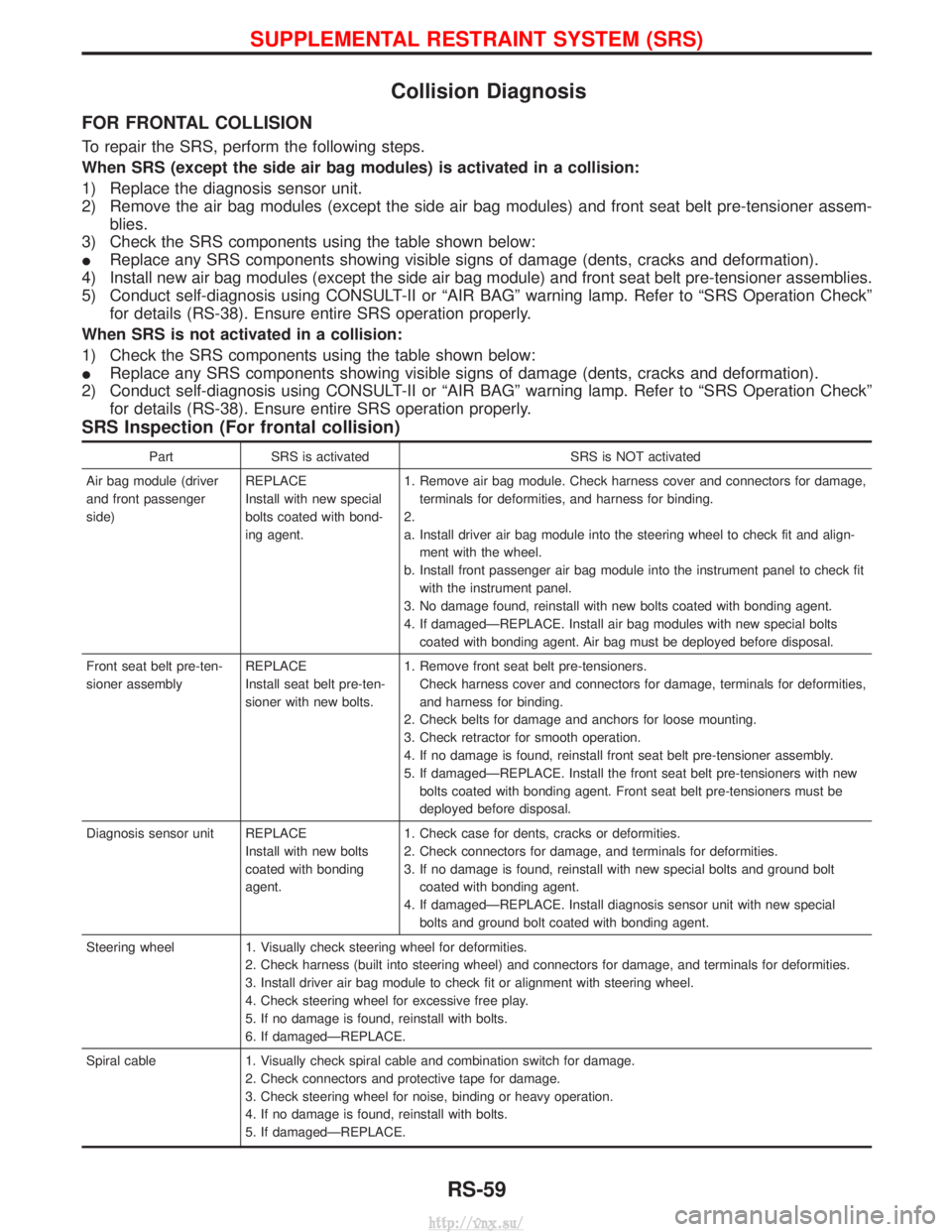
SRS Inspection (For frontal collision)
Part SRS is activated SRS is NOT activated
Air bag module (driver
and front passenger
side) REPLACE
Install with new special
bolts coated with bond-
ing agent.1. Remove air bag module. Check harness cover and connectors for damage,
terminals for deformities, and harness for binding.
2.
a. Install driver air bag module into the steering wheel to check fit and align- ment with the wheel.
b. Install front passenger air bag module into the instrument panel to check fit with the instrument panel.
3. No damage found, reinstall with new bolts coated with bonding agent.
4. If damagedÐREPLACE. Install air bag modules with new special bolts coated with bonding agent. Air bag must be deployed before disposal.
Front seat belt pre-ten-
sioner assembly REPLACE
Install seat belt pre-ten-
sioner with new bolts.1. Remove front seat belt pre-tensioners.
Check harness cover and connectors for damage, terminals for deformities,
and harness for binding.
2. Check belts for damage and anchors for loose mounting.
3. Check retractor for smooth operation.
4. If no damage is found, reinstall front seat belt pre-tensioner assembly.
5. If damagedÐREPLACE. Install the front seat belt pre-tensioners with new bolts coated with bonding agent. Front seat belt pre-tensioners must be
deployed before disposal.
Diagnosis sensor unit REPLACE Install with new bolts
coated with bonding
agent.1. Check case for dents, cracks or deformities.
2. Check connectors for damage, and terminals for deformities.
3. If no damage is found, reinstall with new special bolts and ground bolt
coated with bonding agent.
4. If damagedÐREPLACE. Install diagnosis sensor unit with new special bolts and ground bolt coated with bonding agent.
Steering wheel 1. Visually check steering wheel for deformities. 2. Check harness (built into steering wheel) and connectors for damage, and terminals for deformities.
3. Install driver air bag module to check fit or alignment with steering wheel.
4. Check steering wheel for excessive free play.
5. If no damage is found, reinstall with bolts.
6. If damagedÐREPLACE.
Spiral cable 1. Visually check spiral cable and combination switch for damage. 2. Check connectors and protective tape for damage.
3. Check steering wheel for noise, binding or heavy operation.
4. If no damage is found, reinstall with bolts.
5. If damagedÐREPLACE.
SUPPLEMENTAL RESTRAINT SYSTEM (SRS)
RS-59
http://vnx.su/
Page 1832 of 1833
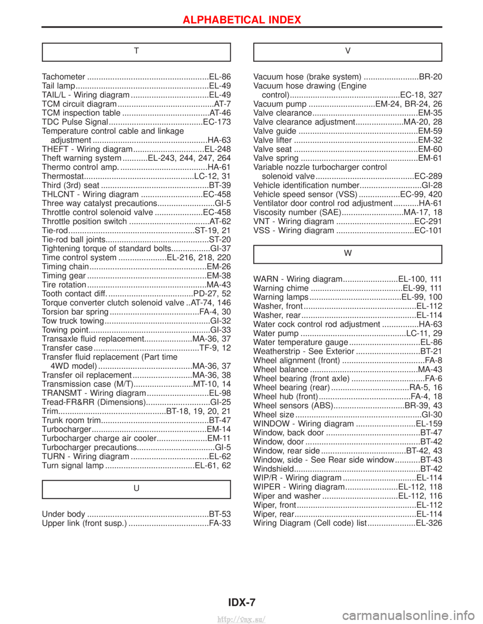
T
Tachometer .....................................................EL-86
Tail lamp ..........................................................EL-49
TAIL/L - Wiring diagram ..................................EL-49
TCM circuit diagram ..........................................AT-7
TCM inspection table ......................................AT-46
TDC Pulse Signal .........................................EC-173
Temperature control cable and linkageadjustment ..................................................HA-63
THEFT - Wiring diagram...............................EL-248
Theft warning system ...........EL-243, 244, 247, 264
Thermo control amp. ......................................HA-61
Thermostat................................................LC-12, 31
Third (3rd) seat ...............................................BT-39
THLCNT - Wiring diagram ...........................EC-458
Three way catalyst precautions.........................GI-5
Throttle control solenoid valve .....................EC-458
Throttle position switch ...................................AT-62
Tie-rod .......................................................ST-19, 21
Tie-rod ball joints.............................................ST-20
Tightening torque of standard bolts.................GI-37
Time control system .....................EL-216, 218, 220
Timing chain ...................................................EM-26
Timing gear ....................................................EM-38
Tire rotation ....................................................MA-43
Tooth contact diff. .....................................PD-27, 52
Torque converter clutch solenoid valve ..AT-74, 146
Torsion bar spring .......................................FA-4, 30
Tow truck towing ..............................................GI-32
Towing point.....................................................GI-33
Transaxle fluid replacement.....................MA-36, 37
Transfer case ..............................................TF-9, 12
Transfer fluid replacement (Part time 4WD model) .........................................MA-36, 37
Transfer oil replacement ..........................MA-36, 38
Transmission case (M/T)..........................MT-10, 14
TRANSMT - Wiring diagram ...........................EL-98
Tread-FR&RR (Dimensions)............................GI-25
Trim...............................................BT-18, 19, 20, 21
Trunk room trim...............................................BT-47
Turbocharger ..................................................EM-14
Turbocharger charge air cooler......................EM-11
Turbocharger precautions..................................GI-5
TURN - Wiring diagram ..................................EL-62
Turn signal lamp .......................................EL-61, 62
U
Under body .....................................................BT-53
Upper link (front susp.) ...................................FA-33 V
Vacuum hose (brake system) ........................BR-20
Vacuum hose drawing (Engine
control)................................................EC-18, 327
Vacuum pump .............................EM-24, BR-24, 26
Valve clearance..............................................EM-35
Valve clearance adjustment.....................MA-20, 28
Valve guide ....................................................EM-59
Valve lifter ......................................................EM-32
Valve seat ......................................................EM-60
Valve spring ...................................................EM-61
Variable nozzle turbocharger control solenoid valve ...........................................EC-289
Vehicle identification number...........................GI-28
Vehicle speed sensor (VSS) ..................EC-99, 420
Ventilator door control rod adjustment ...........HA-61
Viscosity number (SAE)...........................MA-17, 18
VNT - Wiring diagram ..................................EC-291
VSS - Wiring diagram ..................................EC-101
W
WARN - Wiring diagram........................EL-100, 111
Warning chime ........................................EL-99, 111
Warning lamps ........................................EL-99, 100
Washer, front .................................................EL-112
Washer, rear ..................................................EL-114
Water cock control rod adjustment ................HA-63
Water pump ..............................................LC-11, 29
Water temperature gauge ...............................EL-86
Weatherstrip - See Exterior ............................BT-21
Wheel alignment (front) ....................................FA-8
Wheel balance ...............................................MA-43
Wheel bearing (front axle) ................................FA-6
Wheel bearing (rear) ..................................RA-5, 16
Wheel hub (front) ........................................FA-4, 18
Wheel sensors (ABS)...............................BR-39, 43
Wheel size .......................................................GI-30
WINDOW - Wiring diagram ..........................EL-159
Window, back door .........................................BT-47
Window, door ..................................................BT-42
Window, rear side .....................................BT-42, 43
Window, side - See Rear side window ...........BT-43
Windshield.......................................................BT-42
WIP/R - Wiring diagram ................................EL-114
WIPER - Wiring diagram .......................EL-112, 118
Wiper and washer .................................EL-112, 116
Wiper, front ....................................................EL-112
Wiper, rear.....................................................EL-114
Wiring Diagram (Cell code) list .....................EL-326
ALPHABETICAL INDEX
IDX-7
http://vnx.su/