2004 NISSAN TERRANO washer fluid
[x] Cancel search: washer fluidPage 1609 of 1833

Installation
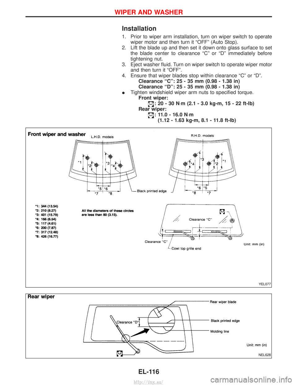
1. Prior to wiper arm installation, turn on wiper switch to operatewiper motor and then turn it ªOFFº (Auto Stop).
2. Lift the blade up and then set it down onto glass surface to set the blade center to clearance ªCº or ªDº immediately before
tightening nut.
3. Eject washer fluid. Turn on wiper switch to operate wiper motor and then turn it ªOFFº.
4. Ensure that wiper blades stop within clearance ªCº or ªDº. Clearance ªCº: 25 - 35 mm (0.98 - 1.38 in)
Clearance ªDº: 25 - 35 mm (0.98 - 1.38 in)
I Tighten windshield wiper arm nuts to specified torque.
Front wiper:
:20-30N ×m (2.1 - 3.0 kg-m, 15 - 22 ft-lb)
Rear wiper:
: 11.0 - 16.0 N ×m
(1.12 - 1.63 kg-m, 8.1 - 11.8 ft-lb)
YEL077
NEL628
WIPER AND WASHER
EL-116
http://vnx.su/
Page 1610 of 1833

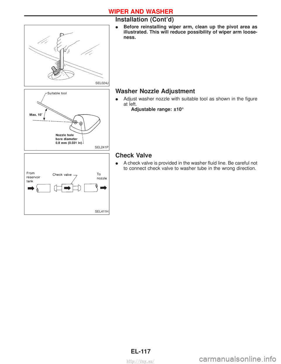
IBefore reinstalling wiper arm, clean up the pivot area as
illustrated. This will reduce possibility of wiper arm loose-
ness.
Washer Nozzle Adjustment
IAdjust washer nozzle with suitable tool as shown in the figure
at left.
Adjustable range: 10É
Check Valve
I A check valve is provided in the washer fluid line. Be careful not
to connect check valve to washer tube in the wrong direction.
SEL024J
SEL241P
SEL411H
WIPER AND WASHER
Installation (Cont'd)
EL-117
http://vnx.su/
Page 1829 of 1833

F
Fan switch ......................................................HA-60
F/FOG - Wiring diagram .................................EL-55
Final drive disassembly............................PD-15, 37
Final drive pre-inspection .........................PD-15, 37
Final drive removal and installation ...............PD-15
Finisher, interior - See Trim ............................BT-18
Finisher, rear panel .........................................BT-18
Floor trim .........................................................BT-18
Fluid temperature sensor (A/T) .....................AT-146
Fluids .............................................MA-5, 17, 20, 36
Flywheel (clutch) .......................................CL-11, 12
Flywheel runout..............................................EM-94
Fog lamp, front .........................................EL-55, 57
Fog lamp, rear ................................................EL-58
Fork rod (M/T) ................................................MT-13
Forward clutch...............................................AT-162
Front axle ....................................................FA-4, 13
Front bumper ....................................................BT-6
Front case (Transfer) ..................................TF-9, 23
Front combination lamp removal andinstallation .....................................................BT-6
Front disc brake .............................................BR-27
Front door .......................................................BT-10
Front Door Trim...............................................BT-19
Front drive shaft (Transfer) .........................TF-9, 19
Front final drive disassembly (4WD) ..............PD-14
Front final drive removal and installa- tion (4WD) ............................................PD-12, 13
Front fog lamp ..........................................EL-55, 57
Front passenger air bag .................................RS-19
Front seat ........................................................BT-34
Front seat belt ..................................................RS-4
Front seat belt pre-tensioner ..........................RS-14
Front side air bag ...........................................RS-20
Front suspension ........................................FA-4, 29
Fuel cut control (at no load & high engine speed).....................................EC-22, 334
Fuel cut solenoid valve ................................EC-399
Fuel cut system ............................................EC-237
Fuel filler lid.......................................................BT-8
Fuel filter replacement...................MA-5, 20, 23, 33
Fuel gauge..................................FE-3, 6, EL-86, 98
Fuel injection system .............................EC-20, 329
Fuel injection timing feed back (Elec- tronic Fuel Injection Pump) ......................EC-197
Fuel precautions ................................................GI-6
Fuel pump and gauge ..............................FE-3, 6, 7
Fuel system ..................................................FE-3, 6
Fuel tank .......................................................FE-3, 6
Fuel temperature sensor ......................EC-123, 395
Fuse ................................................................EL-19
Fuse and fusible link box .............................Foldout
Fuse block ....................................................Foldout
Fusible link ......................................................EL-19 GGarage jack and safety stand .........................GI-31
Gauges .....................................................EL-82, 85
Gear components (M/T) ........MT-11, 14, 16, 21, 23
Generator - See Alternator .............................SC-27
GLOW - Wiring diagram...............................EC-246
Glow control system ....................EC-244, 334, 412
Glow plug .............................................EC-244, 413
Glow relay ............................................EC-246, 419
Grease .........................................MA-17, 39, 40, 44
Ground distribution..........................................EL-20
H
Harness connector ............................................EL-5
Harness connector inspection .........................GI-19
Harness layout ....EL-280, 281, 282, 298, 310, 312,320, 321, 322, 323, 324
Hazard warning lamp................................EL-61, 62
Headlamp ......EL-28, 32, 33, 34, 41, 42, 43, 46, 47
Headlamp aiming control .............EL-41, 42, 43, 46
Headlamp washer .........................................EL-118
Headlining - See Roof trim .............................BT-20
Heat up switch..............................................EC-265
Heated seat .......................................BT-36, EL-151
HEATER - Wiring diagram .............................HA-41
HEATUP - Wiring diagram ...........................EC-266
Height (Dimensions) ........................................GI-10
HFC134a (R134a) system precaution .............HA-3
HFC134a (R134a) system service procedure....................................................HA-15
HFC134a (R134a) system service tools ........HA-11
High clutch ....................................................AT-160
H/LAMP - Wiring diagram ............EL-28, 34, 43, 62
Hood..................................................................BT-6
Hood lock system .............................................BT-6
Horn ..............................................................EL-122
HORN - Wiring diagram................................EL-122
How to erase DTC for OBD system ......EC-33, 344
HSEAT - Wiring diagram...............................EL-151
I
Identification .....................................................HA-2
Identification plate .....................................GI-28, 29
Idle speed...............................................EC-50, 361
Idle speed inspection ...............................MA-20, 26
ILL - Wiring diagram .......................................EL-68
Illumination ................................................EL-67, 68
Injection nozzle ......................................EC-24, 336
Injection nozzle inspection ..................MA-5, 20, 25
Injection timing control valve ........................EC-403
INJPMP - Wiring diagram ...EC-126, 169, 176, 183, 190, 200, 240
Instrument panel .............................................BT-16
INT/L - Wiring diagram....................................EL-74
ALPHABETICAL INDEX
IDX-4
http://vnx.su/
Page 1832 of 1833

T
Tachometer .....................................................EL-86
Tail lamp ..........................................................EL-49
TAIL/L - Wiring diagram ..................................EL-49
TCM circuit diagram ..........................................AT-7
TCM inspection table ......................................AT-46
TDC Pulse Signal .........................................EC-173
Temperature control cable and linkageadjustment ..................................................HA-63
THEFT - Wiring diagram...............................EL-248
Theft warning system ...........EL-243, 244, 247, 264
Thermo control amp. ......................................HA-61
Thermostat................................................LC-12, 31
Third (3rd) seat ...............................................BT-39
THLCNT - Wiring diagram ...........................EC-458
Three way catalyst precautions.........................GI-5
Throttle control solenoid valve .....................EC-458
Throttle position switch ...................................AT-62
Tie-rod .......................................................ST-19, 21
Tie-rod ball joints.............................................ST-20
Tightening torque of standard bolts.................GI-37
Time control system .....................EL-216, 218, 220
Timing chain ...................................................EM-26
Timing gear ....................................................EM-38
Tire rotation ....................................................MA-43
Tooth contact diff. .....................................PD-27, 52
Torque converter clutch solenoid valve ..AT-74, 146
Torsion bar spring .......................................FA-4, 30
Tow truck towing ..............................................GI-32
Towing point.....................................................GI-33
Transaxle fluid replacement.....................MA-36, 37
Transfer case ..............................................TF-9, 12
Transfer fluid replacement (Part time 4WD model) .........................................MA-36, 37
Transfer oil replacement ..........................MA-36, 38
Transmission case (M/T)..........................MT-10, 14
TRANSMT - Wiring diagram ...........................EL-98
Tread-FR&RR (Dimensions)............................GI-25
Trim...............................................BT-18, 19, 20, 21
Trunk room trim...............................................BT-47
Turbocharger ..................................................EM-14
Turbocharger charge air cooler......................EM-11
Turbocharger precautions..................................GI-5
TURN - Wiring diagram ..................................EL-62
Turn signal lamp .......................................EL-61, 62
U
Under body .....................................................BT-53
Upper link (front susp.) ...................................FA-33 V
Vacuum hose (brake system) ........................BR-20
Vacuum hose drawing (Engine
control)................................................EC-18, 327
Vacuum pump .............................EM-24, BR-24, 26
Valve clearance..............................................EM-35
Valve clearance adjustment.....................MA-20, 28
Valve guide ....................................................EM-59
Valve lifter ......................................................EM-32
Valve seat ......................................................EM-60
Valve spring ...................................................EM-61
Variable nozzle turbocharger control solenoid valve ...........................................EC-289
Vehicle identification number...........................GI-28
Vehicle speed sensor (VSS) ..................EC-99, 420
Ventilator door control rod adjustment ...........HA-61
Viscosity number (SAE)...........................MA-17, 18
VNT - Wiring diagram ..................................EC-291
VSS - Wiring diagram ..................................EC-101
W
WARN - Wiring diagram........................EL-100, 111
Warning chime ........................................EL-99, 111
Warning lamps ........................................EL-99, 100
Washer, front .................................................EL-112
Washer, rear ..................................................EL-114
Water cock control rod adjustment ................HA-63
Water pump ..............................................LC-11, 29
Water temperature gauge ...............................EL-86
Weatherstrip - See Exterior ............................BT-21
Wheel alignment (front) ....................................FA-8
Wheel balance ...............................................MA-43
Wheel bearing (front axle) ................................FA-6
Wheel bearing (rear) ..................................RA-5, 16
Wheel hub (front) ........................................FA-4, 18
Wheel sensors (ABS)...............................BR-39, 43
Wheel size .......................................................GI-30
WINDOW - Wiring diagram ..........................EL-159
Window, back door .........................................BT-47
Window, door ..................................................BT-42
Window, rear side .....................................BT-42, 43
Window, side - See Rear side window ...........BT-43
Windshield.......................................................BT-42
WIP/R - Wiring diagram ................................EL-114
WIPER - Wiring diagram .......................EL-112, 118
Wiper and washer .................................EL-112, 116
Wiper, front ....................................................EL-112
Wiper, rear.....................................................EL-114
Wiring Diagram (Cell code) list .....................EL-326
ALPHABETICAL INDEX
IDX-7
http://vnx.su/