2004 NISSAN TERRANO bulb
[x] Cancel search: bulbPage 1494 of 1833
ELECTRICAL SYSTEMSECTION
EL
When you read wiring diagrams:
I Read GI section, ªHOW TO READ WIRING DIAGRAMSº.
CONTENTS
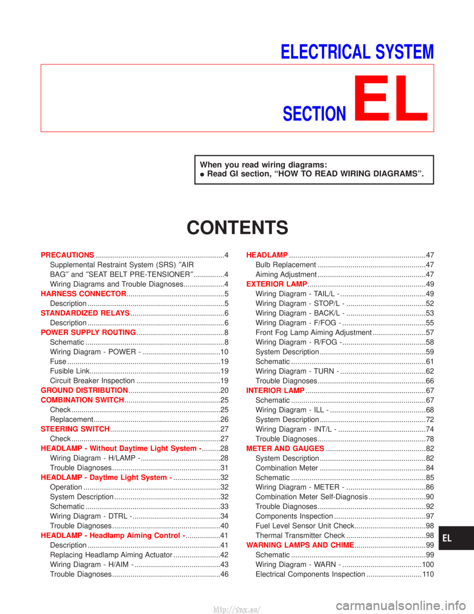
PRECAUTIONS ...............................................................4
Supplemental Restraint System (SRS) ²AIR
BAG² and²SEAT BELT PRE-TENSIONER² ...............4
Wiring Diagrams and Trouble Diagnoses....................4
HARNESS CONNECTOR ................................................5
Description ...................................................................5
STANDARDIZED RELAYS ..............................................6
Description ...................................................................6
POWER SUPPLY ROUTING ...........................................8
Schematic ....................................................................8
Wiring Diagram - POWER - ......................................10
Fuse ........................................................................\
...19
Fusible Link................................................................19
Circuit Breaker Inspection .........................................19
GROUND DISTRIBUTION .............................................20
COMBINATION SWITCH ...............................................25
Check ........................................................................\
.25
Replacement ..............................................................26
STEERING SWITCH ......................................................27
Check ........................................................................\
.27
HEADLAMP - Without Daytime Light System - .........28
Wiring Diagram - H/LAMP -.......................................28
Trouble Diagnoses.....................................................31
HEADLAMP - Daytime Light System - .......................32
Operation ...................................................................32
System Description ....................................................32
Schematic ..................................................................33
Wiring Diagram - DTRL - ...........................................34
Trouble Diagnoses.....................................................40
HEADLAMP - Headlamp Aiming Control - .................41
Description .................................................................41
Replacing Headlamp Aiming Actuator .......................42
Wiring Diagram - H/AIM - ..........................................43
Trouble Diagnoses.....................................................46 HEADLAMP
...................................................................47
Bulb Replacement .....................................................47
Aiming Adjustment .....................................................47
EXTERIOR LAMP ..........................................................49
Wiring Diagram - TAIL/L - ..........................................49
Wiring Diagram - STOP/L - .......................................52
Wiring Diagram - BACK/L - .......................................53
Wiring Diagram - F/FOG - .........................................55
Front Fog Lamp Aiming Adjustment ..........................57
Wiring Diagram - R/FOG -.........................................58
System Description ....................................................59
Schematic ..................................................................61
Wiring Diagram - TURN - ..........................................62
Trouble Diagnoses.....................................................66
INTERIOR LAMP ...........................................................67
Schematic ..................................................................67
Wiring Diagram - ILL - ...............................................68
System Description ....................................................72
Wiring Diagram - INT/L - ...........................................74
Trouble Diagnoses.....................................................78
METER AND GAUGES .................................................82
System Description ....................................................82
Combination Meter ....................................................84
Schematic ..................................................................85
Wiring Diagram - METER - .......................................86
Combination Meter Self-Diagnosis ............................90
Trouble Diagnoses.....................................................92
Components Inspection .............................................97
Fuel Level Sensor Unit Check...................................98
Thermal Transmitter Check .......................................98
WARNING LAMPS AND CHIME ...................................99
Schematic ..................................................................99
Wiring Diagram - WARN - .......................................100
Electrical Components Inspection ........................... 110
http://vnx.su/
Page 1495 of 1833
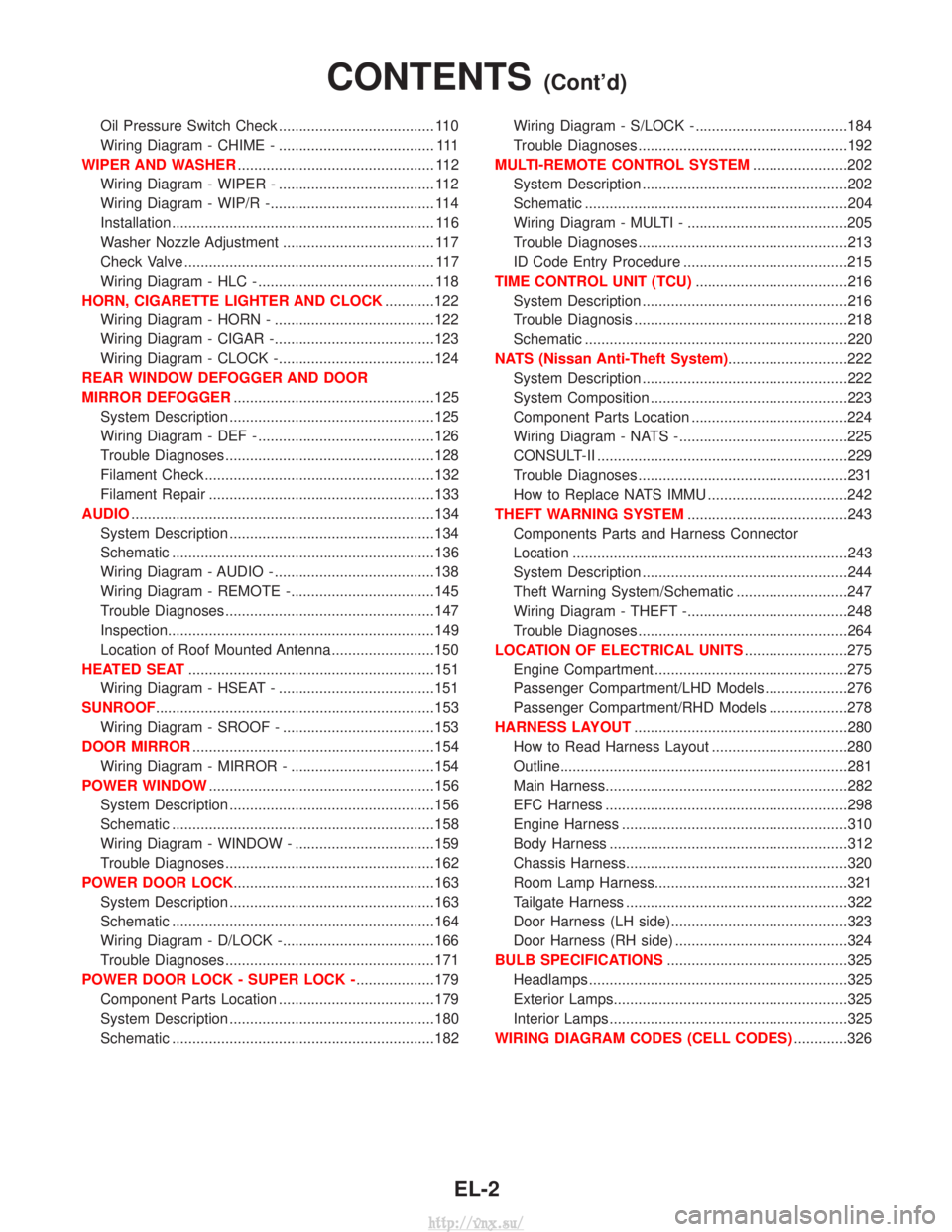
Oil Pressure Switch Check ...................................... 110
Wiring Diagram - CHIME - ...................................... 111
WIPER AND WASHER ................................................ 112
Wiring Diagram - WIPER - ...................................... 112
Wiring Diagram - WIP/R -........................................ 114
Installation ................................................................ 116
Washer Nozzle Adjustment ..................................... 117
Check Valve ............................................................. 117
Wiring Diagram - HLC - ........................................... 118
HORN, CIGARETTE LIGHTER AND CLOCK ............122
Wiring Diagram - HORN - .......................................122
Wiring Diagram - CIGAR -.......................................123
Wiring Diagram - CLOCK -......................................124
REAR WINDOW DEFOGGER AND DOOR
MIRROR DEFOGGER .................................................125
System Description ..................................................125
Wiring Diagram - DEF - ...........................................126
Trouble Diagnoses...................................................128
Filament Check ........................................................132
Filament Repair .......................................................133
AUDIO ........................................................................\
..134
System Description ..................................................134
Schematic ................................................................136
Wiring Diagram - AUDIO - .......................................138
Wiring Diagram - REMOTE -...................................145
Trouble Diagnoses...................................................147
Inspection.................................................................149
Location of Roof Mounted Antenna .........................150
HEATED SEAT ............................................................151
Wiring Diagram - HSEAT - ......................................151
SUNROOF ....................................................................153
Wiring Diagram - SROOF - .....................................153
DOOR MIRROR ...........................................................154
Wiring Diagram - MIRROR - ...................................154
POWER WINDOW .......................................................156
System Description ..................................................156
Schematic ................................................................158
Wiring Diagram - WINDOW - ..................................159
Trouble Diagnoses...................................................162
POWER DOOR LOCK .................................................163
System Description ..................................................163
Schematic ................................................................164
Wiring Diagram - D/LOCK -.....................................166
Trouble Diagnoses...................................................171
POWER DOOR LOCK - SUPER LOCK - ...................179
Component Parts Location ......................................179
System Description ..................................................180
Schematic ................................................................182 Wiring Diagram - S/LOCK - .....................................184
Trouble Diagnoses...................................................192
MULTI-REMOTE CONTROL SYSTEM .......................202
System Description ..................................................202
Schematic ................................................................204
Wiring Diagram - MULTI - .......................................205
Trouble Diagnoses...................................................213
ID Code Entry Procedure ........................................215
TIME CONTROL UNIT (TCU) .....................................216
System Description ..................................................216
Trouble Diagnosis ....................................................218
Schematic ................................................................220
NATS (Nissan Anti-Theft System) .............................222
System Description ..................................................222
System Composition ................................................223
Component Parts Location ......................................224
Wiring Diagram - NATS -.........................................225
CONSULT-II .............................................................229
Trouble Diagnoses...................................................231
How to Replace NATS IMMU ..................................242
THEFT WARNING SYSTEM .......................................243
Components Parts and Harness Connector
Location ...................................................................243
System Description ..................................................244
Theft Warning System/Schematic ...........................247
Wiring Diagram - THEFT -.......................................248
Trouble Diagnoses...................................................264
LOCATION OF ELECTRICAL UNITS .........................275
Engine Compartment ...............................................275
Passenger Compartment/LHD Models ....................276
Passenger Compartment/RHD Models ...................278
HARNESS LAYOUT ....................................................280
How to Read Harness Layout .................................280
Outline......................................................................281
Main Harness...........................................................282
EFC Harness ...........................................................298
Engine Harness .......................................................310
Body Harness ..........................................................312
Chassis Harness......................................................320
Room Lamp Harness...............................................321
Tailgate Harness ......................................................322
Door Harness (LH side)...........................................323
Door Harness (RH side) ..........................................324
BULB SPECIFICATIONS ............................................325
Headlamps ...............................................................325
Exterior Lamps.........................................................325
Interior Lamps ..........................................................325
WIRING DIAGRAM CODES (CELL CODES) .............326
CONTENTS(Cont'd)
EL-2
http://vnx.su/
Page 1524 of 1833
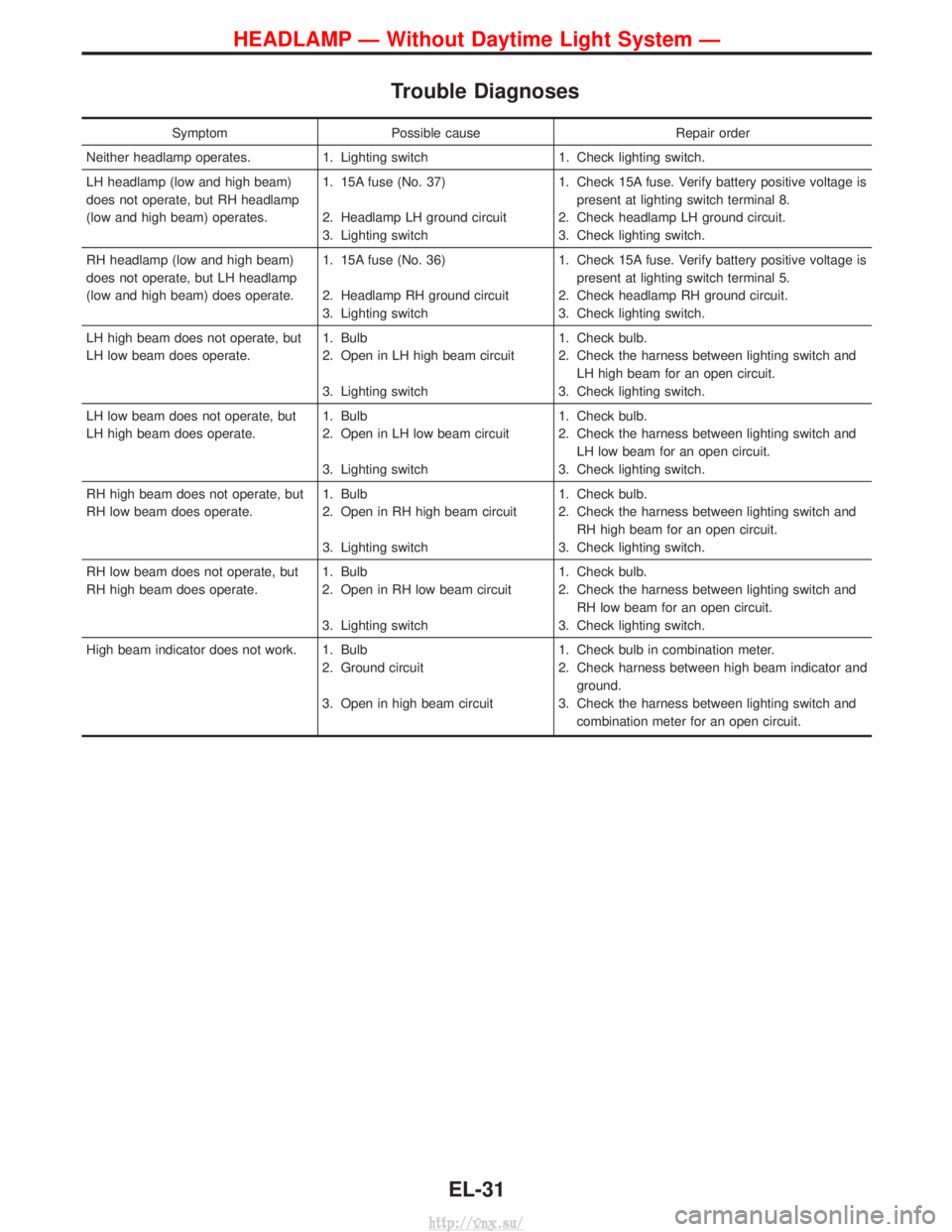
Trouble Diagnoses
SymptomPossible cause Repair order
Neither headlamp operates. 1. Lighting switch 1. Check lighting switch.
LH headlamp (low and high beam)
does not operate, but RH headlamp
(low and high beam) operates. 1. 15A fuse (No. 37)
2. Headlamp LH ground circuit
3. Lighting switch1. Check 15A fuse. Verify battery positive voltage is
present at lighting switch terminal 8.
2. Check headlamp LH ground circuit.
3. Check lighting switch.
RH headlamp (low and high beam)
does not operate, but LH headlamp
(low and high beam) does operate. 1. 15A fuse (No. 36)
2. Headlamp RH ground circuit
3. Lighting switch1. Check 15A fuse. Verify battery positive voltage is
present at lighting switch terminal 5.
2. Check headlamp RH ground circuit.
3. Check lighting switch.
LH high beam does not operate, but
LH low beam does operate. 1. Bulb
2. Open in LH high beam circuit
3. Lighting switch1. Check bulb.
2. Check the harness between lighting switch and
LH high beam for an open circuit.
3. Check lighting switch.
LH low beam does not operate, but
LH high beam does operate. 1. Bulb
2. Open in LH low beam circuit
3. Lighting switch1. Check bulb.
2. Check the harness between lighting switch and
LH low beam for an open circuit.
3. Check lighting switch.
RH high beam does not operate, but
RH low beam does operate. 1. Bulb
2. Open in RH high beam circuit
3. Lighting switch1. Check bulb.
2. Check the harness between lighting switch and
RH high beam for an open circuit.
3. Check lighting switch.
RH low beam does not operate, but
RH high beam does operate. 1. Bulb
2. Open in RH low beam circuit
3. Lighting switch1. Check bulb.
2. Check the harness between lighting switch and
RH low beam for an open circuit.
3. Check lighting switch.
High beam indicator does not work. 1. Bulb 2. Ground circuit
3. Open in high beam circuit1. Check bulb in combination meter.
2. Check harness between high beam indicator and
ground.
3. Check the harness between lighting switch and combination meter for an open circuit.
HEADLAMP Ð Without Daytime Light System Ð
EL-31
http://vnx.su/
Page 1540 of 1833
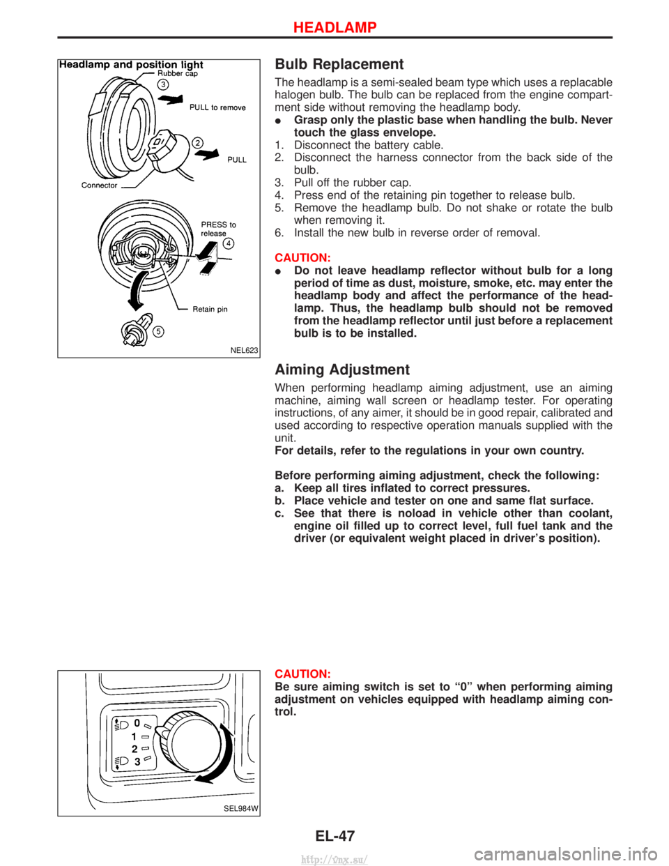
Bulb Replacement
The headlamp is a semi-sealed beam type which uses a replacable
halogen bulb. The bulb can be replaced from the engine compart-
ment side without removing the headlamp body.
IGrasp only the plastic base when handling the bulb. Never
touch the glass envelope.
1. Disconnect the battery cable.
2. Disconnect the harness connector from the back side of the bulb.
3. Pull off the rubber cap.
4. Press end of the retaining pin together to release bulb.
5. Remove the headlamp bulb. Do not shake or rotate the bulb when removing it.
6. Install the new bulb in reverse order of removal.
CAUTION:
I Do not leave headlamp reflector without bulb for a long
period of time as dust, moisture, smoke, etc. may enter the
headlamp body and affect the performance of the head-
lamp. Thus, the headlamp bulb should not be removed
from the headlamp reflector until just before a replacement
bulb is to be installed.
Aiming Adjustment
When performing headlamp aiming adjustment, use an aiming
machine, aiming wall screen or headlamp tester. For operating
instructions, of any aimer, it should be in good repair, calibrated and
used according to respective operation manuals supplied with the
unit.
For details, refer to the regulations in your own country.
Before performing aiming adjustment, check the following:
a. Keep all tires inflated to correct pressures.
b. Place vehicle and tester on one and same flat surface.
c. See that there is noload in vehicle other than coolant,
engine oil filled up to correct level, full fuel tank and the
driver (or equivalent weight placed in driver's position).
CAUTION:
Be sure aiming switch is set to ª0º when performing aiming
adjustment on vehicles equipped with headlamp aiming con-
trol.
NEL623
SEL984W
HEADLAMP
EL-47
http://vnx.su/
Page 1559 of 1833
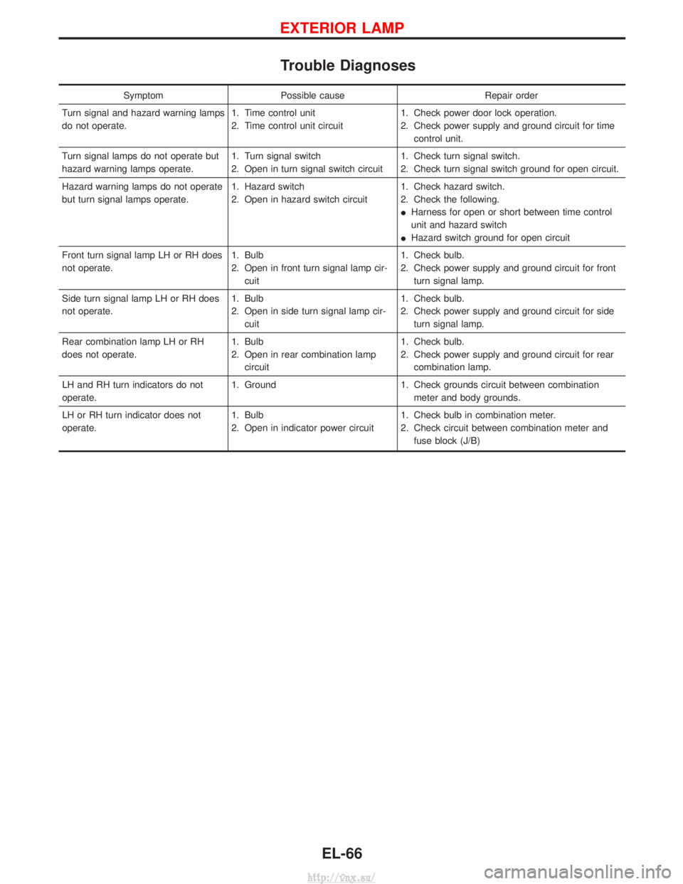
Trouble Diagnoses
SymptomPossible cause Repair order
Turn signal and hazard warning lamps
do not operate. 1. Time control unit
2. Time control unit circuit1. Check power door lock operation.
2. Check power supply and ground circuit for time
control unit.
Turn signal lamps do not operate but
hazard warning lamps operate. 1. Turn signal switch
2. Open in turn signal switch circuit1. Check turn signal switch.
2. Check turn signal switch ground for open circuit.
Hazard warning lamps do not operate
but turn signal lamps operate. 1. Hazard switch
2. Open in hazard switch circuit1. Check hazard switch.
2. Check the following.
I
Harness for open or short between time control
unit and hazard switch
I Hazard switch ground for open circuit
Front turn signal lamp LH or RH does
not operate. 1. Bulb
2. Open in front turn signal lamp cir-
cuit 1. Check bulb.
2. Check power supply and ground circuit for front
turn signal lamp.
Side turn signal lamp LH or RH does
not operate. 1. Bulb
2. Open in side turn signal lamp cir-
cuit 1. Check bulb.
2. Check power supply and ground circuit for side
turn signal lamp.
Rear combination lamp LH or RH
does not operate. 1. Bulb
2. Open in rear combination lamp
circuit 1. Check bulb.
2. Check power supply and ground circuit for rear
combination lamp.
LH and RH turn indicators do not
operate. 1. Ground
1. Check grounds circuit between combination
meter and body grounds.
LH or RH turn indicator does not
operate. 1. Bulb
2. Open in indicator power circuit1. Check bulb in combination meter.
2. Check circuit between combination meter and
fuse block (J/B)
EXTERIOR LAMP
EL-66
http://vnx.su/
Page 1818 of 1833
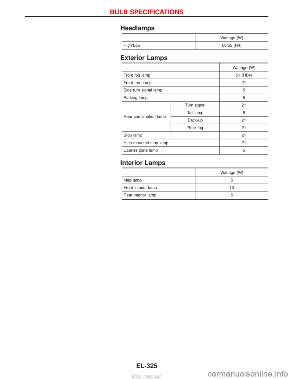
Headlamps
Wattage (W)
High/Low 60/55 (H4)
Exterior Lamps
Wattage (W)
Front fog lamp 51 (HB4)
Front turn lamp 21
Side turn signal lamp 5
Parking lamp 5
Rear combination lamp Turn signal 21
Tail lamp 5Back-up 21
Rear fog 21
Stop lamp 21
High-mounted stop lamp 21
License plate lamp 5
Interior Lamps
Wattage (W)
Map lamp 5
Front interior lamp 10
Rear interior lamp 5
BULB SPECIFICATIONS
EL-325
http://vnx.su/