2004 NISSAN TERRANO battery replacement
[x] Cancel search: battery replacementPage 1324 of 1833
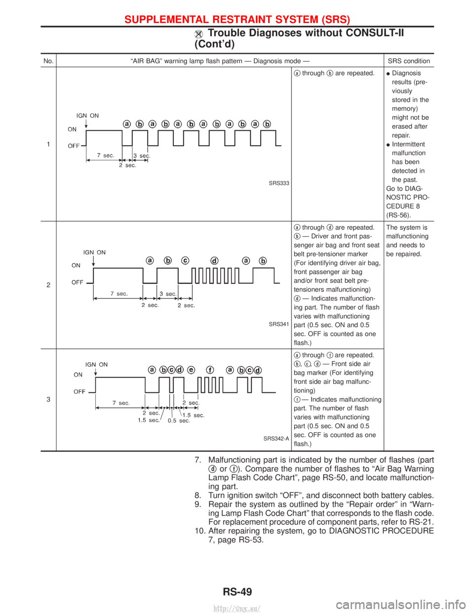
No.ªAIR BAGº warning lamp flash pattern Ð Diagnosis mode Ð SRS condition
1
SRS333
qathrough qbare repeated.
IDiagnosis
results (pre-
viously
stored in the
memory)
might not be
erased after
repair.
I Intermittent
malfunction
has been
detected in
the past.
Go to DIAG-
NOSTIC PRO-
CEDURE 8
(RS-56).
2
SRS341
qathrough qdare repeated.
q
bÐ Driver and front pas-
senger air bag and front seat
belt pre-tensioner marker
(For identifying driver air bag,
front passenger air bag
and/or front seat belt pre-
tensioners malfunctioning)
q
dÐ Indicates malfunction-
ing part. The number of flash
varies with malfunctioning
part (0.5 sec. ON and 0.5
sec. OFF is counted as one
flash.) The system is
malfunctioning
and needs to
be repaired.
3
SRS342-A
qathrough qfare repeated.
q
b, qc,qdÐ Front side air
bag marker (For identifying
front side air bag malfunc-
tioning)
q
fÐ Indicates malfunctioning
part. The number of flash
varies with malfunctioning
part (0.5 sec. ON and 0.5
sec. OFF is counted as one
flash.)
7. Malfunctioning part is indicated by the number of flashes (part q
dorqf). Compare the number of flashes to ªAir Bag Warning
Lamp Flash Code Chartº, page RS-50, and locate malfunction-
ing part.
8. Turn ignition switch ªOFFº, and disconnect both battery cables.
9. Repair the system as outlined by the ªRepair orderº in ªWarn- ing Lamp Flash Code Chartº that corresponds to the flash code.
For replacement procedure of component parts, refer to RS-21.
10. After repairing the system, go to DIAGNOSTIC PROCEDURE 7, page RS-53.
SUPPLEMENTAL RESTRAINT SYSTEM (SRS)
Trouble Diagnoses without CONSULT-II
(Cont'd)
RS-49
http://vnx.su/
Page 1328 of 1833
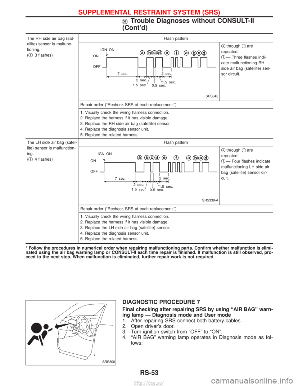
The RH side air bag (sat-
ellite) sensor is malfunc-
tioning.
(q
f: 3 flashes) Flash pattern
SRS340
qathrough
qfare
repeated.
q
fÐ Three flashes indi-
cate malfunctioning RH
side air bag (satellite) sen-
sor circuit.
Repair order (ªRecheck SRS at each replacement.º)
1. Visually check the wiring harness connection.
2. Replace the harness if it has visible damage.
3. Replace the RH side air bag (satellite) sensor.
4. Replace the diagnosis sensor unit.
5. Replace the related harness.
The LH side air bag (satel-
lite) sensor is malfunction-
ing.
( q
f: 4 flashes) Flash pattern
SRS339-A
qathrough
qfare
repeated.
q
fÐ Four flashes indicate
malfunctioning LH side air
bag (satellite) sensor cir-
cuit.
Repair order (ªRecheck SRS at each replacement.º)
1. Visually check the wiring harness connection.
2. Replace the harness if it has visible damage.
3. Replace the LH side air bag (satellite) sensor.
4. Replace the diagnosis sensor unit.
5. Replace the related harness.
* Follow the procedures in numerical order when repairing malfunctioning parts. Confirm whether malfunction is elimi-
nated using the air bag warning lamp or CONSULT-II each time repair is finished. If malfunction is still observed, pro-
ceed to the next step. When malfunction is eliminated, further repair work is not required.
DIAGNOSTIC PROCEDURE 7
Final checking after repairing SRS by using ªAIR BAGº warn-
ing lamp Ð Diagnosis mode and User mode
1. After repairing SRS connect both battery cables.
2. Open driver's door.
3. Turn ignition switch from ªOFFº to ªONº.
4. ªAIR BAGº warning lamp operates in Diagnosis mode as fol- lows:
SRS800
SUPPLEMENTAL RESTRAINT SYSTEM (SRS)
Trouble Diagnoses without CONSULT-II
(Cont'd)
RS-53
http://vnx.su/
Page 1540 of 1833
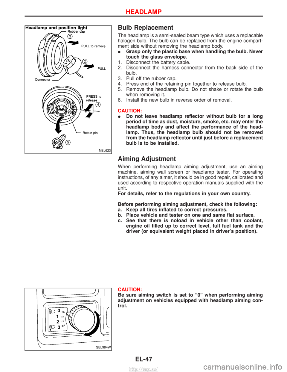
Bulb Replacement
The headlamp is a semi-sealed beam type which uses a replacable
halogen bulb. The bulb can be replaced from the engine compart-
ment side without removing the headlamp body.
IGrasp only the plastic base when handling the bulb. Never
touch the glass envelope.
1. Disconnect the battery cable.
2. Disconnect the harness connector from the back side of the bulb.
3. Pull off the rubber cap.
4. Press end of the retaining pin together to release bulb.
5. Remove the headlamp bulb. Do not shake or rotate the bulb when removing it.
6. Install the new bulb in reverse order of removal.
CAUTION:
I Do not leave headlamp reflector without bulb for a long
period of time as dust, moisture, smoke, etc. may enter the
headlamp body and affect the performance of the head-
lamp. Thus, the headlamp bulb should not be removed
from the headlamp reflector until just before a replacement
bulb is to be installed.
Aiming Adjustment
When performing headlamp aiming adjustment, use an aiming
machine, aiming wall screen or headlamp tester. For operating
instructions, of any aimer, it should be in good repair, calibrated and
used according to respective operation manuals supplied with the
unit.
For details, refer to the regulations in your own country.
Before performing aiming adjustment, check the following:
a. Keep all tires inflated to correct pressures.
b. Place vehicle and tester on one and same flat surface.
c. See that there is noload in vehicle other than coolant,
engine oil filled up to correct level, full fuel tank and the
driver (or equivalent weight placed in driver's position).
CAUTION:
Be sure aiming switch is set to ª0º when performing aiming
adjustment on vehicles equipped with headlamp aiming con-
trol.
NEL623
SEL984W
HEADLAMP
EL-47
http://vnx.su/
Page 1628 of 1833
Service instruction
ItemRadio linked with IMMU and/or SECU
Battery disconnection No additional action required
Radio needs repair Repair needs to be done by authorised representative of radio manufacturer since radio cannot be operated unless it is reset to NEW state, using special decoding equipment
Replacement of radio by new part Radio is delivered in NEW state. If possible, the radio will automatically link up with the immobiliser system. If this appears not possible, CATS code needs to be manually input
Transferring radio to another vehicle/
replacement of radio by an ªoldº part Radio needs to be reset to NEW state by authorised representative of radio manufac-
turer
Replacement of IMMU by new part Radio will request for CATS code input prior to establishing the link with the IMMU
Replacement of IMMU by old part If a radio code has already been stored in memory of the IMMU, the radio cannot be linked to it. After switching on the radio, it will display ªSECUREº after 1 minute. Opera-
tion can only be established after resetting the ratio by an authorised representative of
radio manufacturer
CATS code input procedure
1. Radio displays ªCODE INº after the power is switched ON.
2. Enter CATS code (4-digits) by pressing the preset buttons (using 1 to 4).Press the preset buttons for the necessary amount of times for the number of each digits.
e.g. CATS code is ª5432º
Press No. 1 preset button for 5 times
Press No. 2 preset button for 4 times
Press No. 3 preset button for 3 times
Press No. 4 preset button for 2 times
3. Press the
button.
4. If the code is OK, the radio will power ON. If the code is NG, the radio will be locked up as below. After the lock up, the radio will display ªCODE INº
again.
1st to 3rd attempt: The radio will be locked for 10 seconds after each attempt
4th to 20th attempt: The radio will be locked for 60 minutes after each attempt
Over 20th attempt: The radio will be locked completely
SPEED DEPENDENT VOLUME CONTROL
Description
If activated, the radio output volume will be automatically adjusted to compensate for increased driving noises
at higher driving speeds. The radio receives a speed signal from the combination meter and selects the out-
put volume.
AUDIO
System Description (Cont'd)
EL-135
http://vnx.su/
Page 1827 of 1833
A
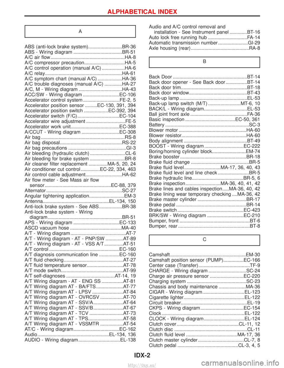
ABS (anti-lock brake system).........................BR-36
ABS - Wiring diagram ....................................BR-51
A/C air flow .......................................................HA-8
A/C compressor precaution..............................HA-5
A/C control operation (manual A/C) .................HA-6
A/C relay.........................................................HA-61
A/C symptom chart (manual A/C) ..................HA-36
A/C trouble diagnoses (manual A/C) .............HA-27
A/C, M - Wiring diagram ................................HA-43
ACC/SW - Wiring diagram ...........................EC-106
Accelerator control system ...........................FE-2, 5
Accelerator position sensor .........EC-130, 391, 394
Accelerator position switch ..................EC-392, 394
Accelerator switch (F/C) ...............................EC-104
Accelerator wire adjustment .............................FE-5
Accelerator work unit....................................EC-388
A/CCUT - Wiring diagram ............................EC-308
Air bag ..............................................................RS-8
Air bag disposal..............................................RS-22
Air bag precautions ...........................................GI-3
Air bleeding (hydraulic clutch) ..........................CL-6
Air bleeding for brake system ..........................BR-8
Air cleaner filter replacement ..............MA-5, 20, 24
Air conditioner cut control ..............EC-22, 334, 463
Air control cable adjustment...........................HA-62
Air flow meter - See Mass air flowsensor .................................................EC-88, 379
Alternator ........................................................SC-27
Angular tightening application..........................EM-3
Antenna.................................................EL-134, 150
Anti-lock brake system - See ABS .................BR-38
Anti-lock brake system - Wiring diagram .......................................................BR-51
APS - Wiring diagram ..................................EC-133
ASCD vacuum hose ......................................MA-40
A/T - Wiring diagram .........................................AT-7
A/T - Wiring diagram - AT - PNP/SW .............AT-89
A/T - Wiring diagram - AT - VSS A/T ..............AT-51
A/T control ....................................................EC-160
A/T diagnosis communication line ...............EC-160
A/T fluid checking ............................................AT-27
A/T fluid temperature sensor...........................AT-78
A/T mode switch..............................................AT-99
A/T self-diagnoses ....................................AT-14, 19
A/T Wiring diagram - AT - ENG SS ................AT-81
A/T Wiring diagram AT - BA/FTS ....................AT-77
A/T Wiring diagram AT - LPSV .......................AT-84
A/T Wiring diagram AT - OVRCSV .................AT-70
A/T Wiring diagram AT - SSV/A ......................AT-64
A/T Wiring diagram AT - SSV/B ......................AT-67
A/T Wiring diagram AT - TCV .........................AT-73
A/T Wiring diagram AT - TPS..........................AT-58
A/T Wiring diagram AT - VSSMTR .................AT-54
AT/C - Wiring diagram..................................EC-162
Audio .....................................................EL-134, 136
AUDIO - Wiring diagram ...............................EL-138 Audio and A/C control removal and
installation - See Instrument panel .............BT-16
Auto lock free running hub .............................FA-14
Automatic transmission number ......................GI-29
Axle housing (rear) ...........................................RA-8
B
Back Door .......................................................BT-14
Back door opener - See Back door ................BT-14
Back door trim.................................................BT-18
Back door window...........................................BT-43
Back-up lamp ..................................................EL-53
Back-up lamp switch (M/T) ........................MT-6, 10
BACK/L - Wiring diagram................................EL-53
Ball joint front axle ..........................................FA-36
Basic inspection .....................................EC-50, 361
Battery ..............................................................SC-3
Blower motor ..................................................HA-60
Blower resistor................................................HA-60
Body alignment ...............................................BT-49
BOOST - Wiring diagram .............................EC-222
Boring/horning cylinder block.........................EM-74
Brake booster .................................................BR-18
Brake fluid change ...........................................BR-5
Brake fluid level ...........................MA-17, 36, 40, 43
Brake fluid level and line check .......................BR-5
Brake hydraulic line......................................BR-5, 6
Brake inspection ..........................MA-36, 40, 41, 42
Brake lines and cables inspection.....MA-36, 40, 42
Brake lining wear temporary checking ....MA-36, 42
Brake master cylinder ....................................BR-17
Brake pedal ....................................................BR-14
Brake switch .................................................EC-423
BRK/SW - Wiring diagram ...........................EC-210
Bumper, front ....................................................BT-6
Bumper, rear .....................................................BT-8C
Camshaft ........................................................EM-30
Camshaft position sensor (PUMP)...............EC-166
Center case (Transfer) ......................................TF-9
CHARGE - Wiring diagram ............................SC-24
Charge air pressure sensor .........................EC-220
Charging system ............................................SC-23
Chassis and body maintenance ....................MA-36
CIGAR - Wiring diagram ...............................EL-123
Cigarette lighter.............................................EL-122
Circuit breaker.................................................EL-19
CKPS - Wiring diagram ................................EC-154
Clock .............................................................EL-122
CLOCK - Wiring diagram ..............................EL-124
Clutch cover ..............................................CL-11, 12
Clutch disc ......................................................CL-11
Clutch fluid level ......................................MA-17, 36
Clutch master cylinder ..................................CL-7, 8
Clutch pedal .............................................CL-3, 4, 5
ALPHABETICAL INDEX
IDX-2
http://vnx.su/