2004 NISSAN TERRANO belt
[x] Cancel search: beltPage 1338 of 1833
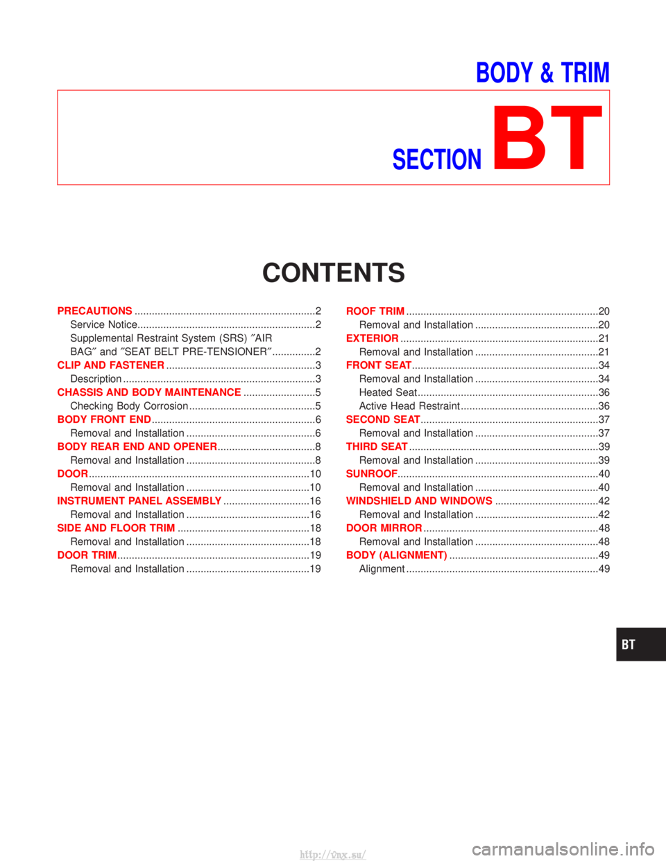
BODY & TRIM
SECTION
BT
CONTENTS
PRECAUTIONS ...............................................................2
Service Notice..............................................................2
Supplemental Restraint System (SRS) ²AIR
BAG² and²SEAT BELT PRE-TENSIONER² ...............2
CLIP AND FASTENER ....................................................3
Description ...................................................................3
CHASSIS AND BODY MAINTENANCE .........................5
Checking Body Corrosion ............................................5
BODY FRONT END .........................................................6
Removal and Installation .............................................6
BODY REAR END AND OPENER ..................................8
Removal and Installation .............................................8
DOOR ........................................................................\
.....10
Removal and Installation ...........................................10
INSTRUMENT PANEL ASSEMBLY ..............................16
Removal and Installation ...........................................16
SIDE AND FLOOR TRIM ..............................................18
Removal and Installation ...........................................18
DOOR TRIM ...................................................................19
Removal and Installation ...........................................19 ROOF TRIM
...................................................................20
Removal and Installation ...........................................20
EXTERIOR .....................................................................21
Removal and Installation ...........................................21
FRONT SEAT .................................................................34
Removal and Installation ...........................................34
Heated Seat ...............................................................36
Active Head Restraint ................................................36
SECOND SEAT ..............................................................37
Removal and Installation ...........................................37
THIRD SEAT ..................................................................39
Removal and Installation ...........................................39
SUNROOF ......................................................................40
Removal and Installation ...........................................40
WINDSHIELD AND WINDOWS ....................................42
Removal and Installation ...........................................42
DOOR MIRROR .............................................................48
Removal and Installation ...........................................48
BODY (ALIGNMENT) ....................................................49
Alignment ...................................................................49
http://vnx.su/
Page 1339 of 1833
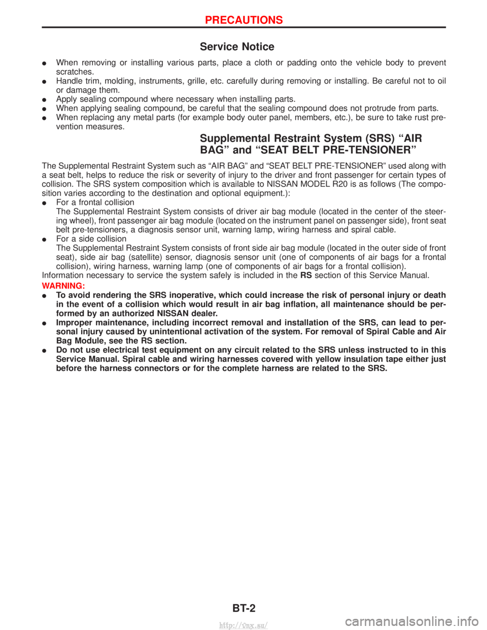
Service Notice
IWhen removing or installing various parts, place a cloth or padding onto the vehicle body to prevent
scratches.
I Handle trim, molding, instruments, grille, etc. carefully during removing or installing. Be careful not to oil
or damage them.
I Apply sealing compound where necessary when installing parts.
I When applying sealing compound, be careful that the sealing compound does not protrude from parts.
I When replacing any metal parts (for example body outer panel, members, etc.), be sure to take rust pre-
vention measures.
Supplemental Restraint System (SRS) ªAIR
BAGº and ªSEAT BELT PRE-TENSIONERº
The Supplemental Restraint System such as ªAIR BAGº and ªSEAT BELT PRE-TENSIONERº used along with
a seat belt, helps to reduce the risk or severity of injury to the driver and front passenger for certain types of
collision. The SRS system composition which is available to NISSAN MODEL R20 is as follows (The compo-
sition varies according to the destination and optional equipment.):
IFor a frontal collision
The Supplemental Restraint System consists of driver air bag module (located in the center of the steer-
ing wheel), front passenger air bag module (located on the instrument panel on passenger side), front seat
belt pre-tensioners, a diagnosis sensor unit, warning lamp, wiring harness and spiral cable.
I For a side collision
The Supplemental Restraint System consists of front side air bag module (located in the outer side of front
seat), side air bag (satellite) sensor, diagnosis sensor unit (one of components of air bags for a frontal
collision), wiring harness, warning lamp (one of components of air bags for a frontal collision).
Information necessary to service the system safely is included in the RSsection of this Service Manual.
WARNING:
I To avoid rendering the SRS inoperative, which could increase the risk of personal injury or death
in the event of a collision which would result in air bag inflation, all maintenance should be per-
formed by an authorized NISSAN dealer.
I Improper maintenance, including incorrect removal and installation of the SRS, can lead to per-
sonal injury caused by unintentional activation of the system. For removal of Spiral Cable and Air
Bag Module, see the RS section.
I Do not use electrical test equipment on any circuit related to the SRS unless instructed to in this
Service Manual. Spiral cable and wiring harnesses covered with yellow insulation tape either just
before the harness connectors or for the complete harness are related to the SRS.
PRECAUTIONS
BT-2
http://vnx.su/
Page 1398 of 1833
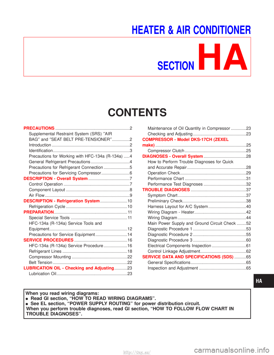
HEATER & AIR CONDITIONERSECTION
HA
CONTENTS
PRECAUTIONS ...............................................................2
Supplemental Restraint System (SRS) ²AIR
BAG² and²SEAT BELT PRE-TENSIONER² ...............2
Introduction ..................................................................2
Identification .................................................................3
Precautions for Working with HFC-134a (R-134a) .....4
General Refrigerant Precautions .................................4
Precautions for Refrigerant Connection ......................5
Precautions for Servicing Compressor ........................6
DESCRIPTION - Overall System ...................................7
Control Operation ........................................................7
Component Layout ......................................................8
Air Flow ........................................................................\
9
DESCRIPTION - Refrigeration System .......................10
Refrigeration Cycle ....................................................10
PREPARATION .............................................................. 11
Special Service Tools ................................................ 11
HFC-134a (R-134a) Service Tools and
Equipment ..................................................................12
Precautions for Service Equipment ...........................14
SERVICE PROCEDURES .............................................16
HFC-134a (R-134a) Service Procedure ....................16
Refrigerant Lines .......................................................18
Compressor Mounting ...............................................22
Belt Tension ...............................................................22
LUBRICATION OIL - Checking and Adjusting ...........23
Lubrication Oil ............................................................23 Maintenance of Oil Quantity in Compressor .............23
Checking and Adjusting .............................................23
COMPRESSOR - Model DKS-17CH (ZEXEL
make) ........................................................................\
.....25
Compressor Clutch ....................................................25
DIAGNOSES - Overall System ....................................28
How to Perform Trouble Diagnoses for Quick
and Accurate Repair ..................................................28
Operation Check ........................................................29
Performance Chart ....................................................31
Performance Test Diagnoses ....................................32
TROUBLE DIAGNOSES ...............................................37
Symptom Chart ..........................................................37
Preliminary Check......................................................38
Harness Layout for A/C System ................................40
Wiring Diagram - Heater............................................42
Wiring Diagram ..........................................................44
Main Power Supply and Ground Circuit Check ........52
Diagnostic Procedure 1 .............................................53
Diagnostic Procedure 2 .............................................55
Diagnostic Procedure 3 .............................................60
Electrical Components Inspection .............................61
Control Linkage Adjustment.......................................62
SERVICE DATA AND SPECIFICATIONS (SDS) ..........65
General Specifications ...............................................65
Inspection and Adjustment ........................................65
When you read wiring diagrams:
I Read GI section, ªHOW TO READ WIRING DIAGRAMSº.
I See EL section, ªPOWER SUPPLY ROUTINGº for power distribution circuit.
When you perform trouble diagnoses, read GI section, ªHOW TO FOLLOW FLOW CHART IN
TROUBLE DIAGNOSESº.
http://vnx.su/
Page 1399 of 1833
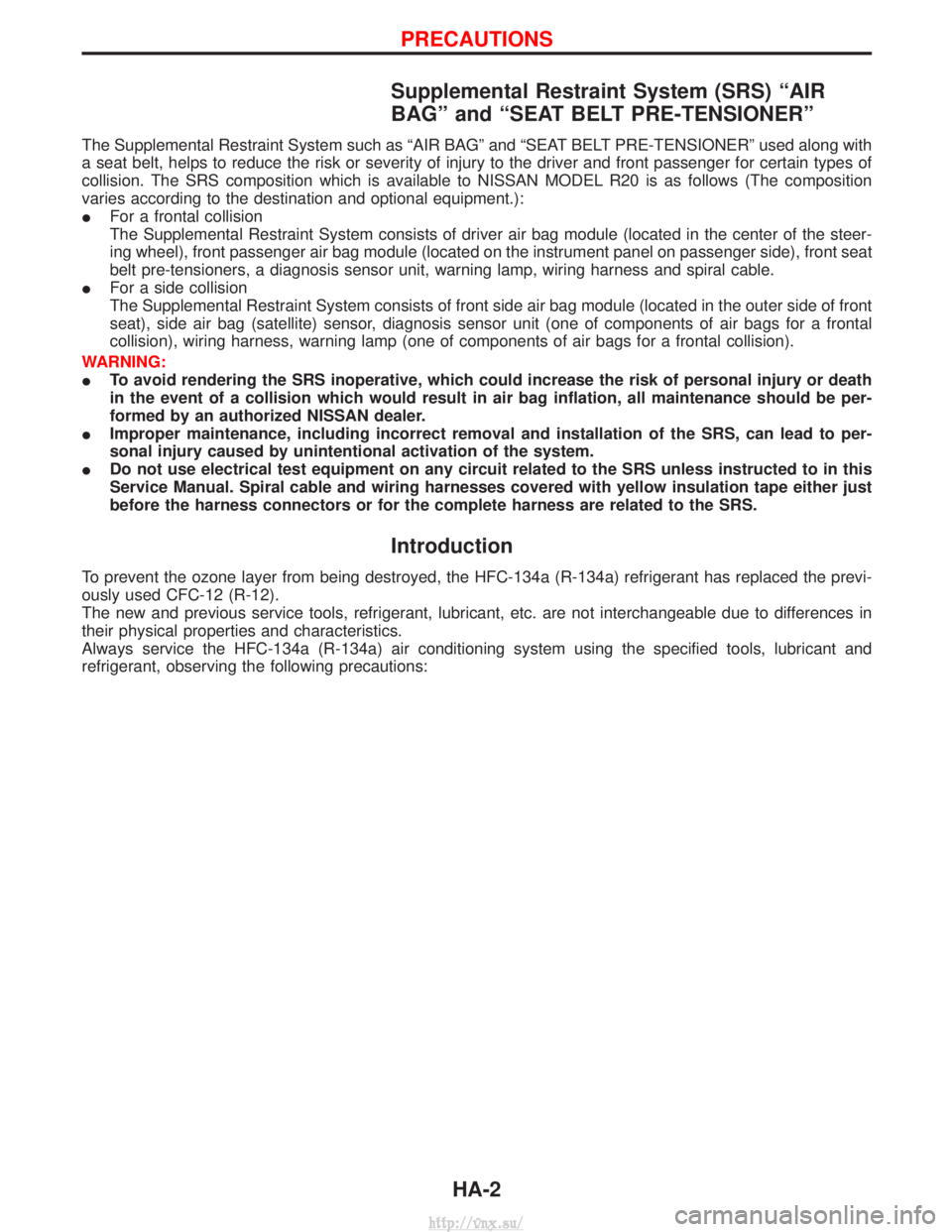
Supplemental Restraint System (SRS) ªAIR
BAGº and ªSEAT BELT PRE-TENSIONERº
The Supplemental Restraint System such as ªAIR BAGº and ªSEAT BELT PRE-TENSIONERº used along with
a seat belt, helps to reduce the risk or severity of injury to the driver and front passenger for certain types of
collision. The SRS composition which is available to NISSAN MODEL R20 is as follows (The composition
varies according to the destination and optional equipment.):
IFor a frontal collision
The Supplemental Restraint System consists of driver air bag module (located in the center of the steer-
ing wheel), front passenger air bag module (located on the instrument panel on passenger side), front seat
belt pre-tensioners, a diagnosis sensor unit, warning lamp, wiring harness and spiral cable.
I For a side collision
The Supplemental Restraint System consists of front side air bag module (located in the outer side of front
seat), side air bag (satellite) sensor, diagnosis sensor unit (one of components of air bags for a frontal
collision), wiring harness, warning lamp (one of components of air bags for a frontal collision).
WARNING:
I To avoid rendering the SRS inoperative, which could increase the risk of personal injury or death
in the event of a collision which would result in air bag inflation, all maintenance should be per-
formed by an authorized NISSAN dealer.
I Improper maintenance, including incorrect removal and installation of the SRS, can lead to per-
sonal injury caused by unintentional activation of the system.
I Do not use electrical test equipment on any circuit related to the SRS unless instructed to in this
Service Manual. Spiral cable and wiring harnesses covered with yellow insulation tape either just
before the harness connectors or for the complete harness are related to the SRS.
Introduction
To prevent the ozone layer from being destroyed, the HFC-134a (R-134a) refrigerant has replaced the previ-
ously used CFC-12 (R-12).
The new and previous service tools, refrigerant, lubricant, etc. are not interchangeable due to differences in
their physical properties and characteristics.
Always service the HFC-134a (R-134a) air conditioning system using the specified tools, lubricant and
refrigerant, observing the following precautions:
PRECAUTIONS
HA-2
http://vnx.su/
Page 1419 of 1833
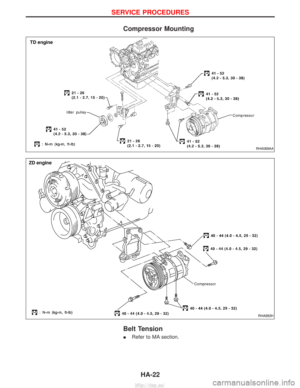
Compressor Mounting
Belt Tension
IRefer to MA section.
RHA069AA
RHA893H
SERVICE PROCEDURES
HA-22
http://vnx.su/
Page 1435 of 1833
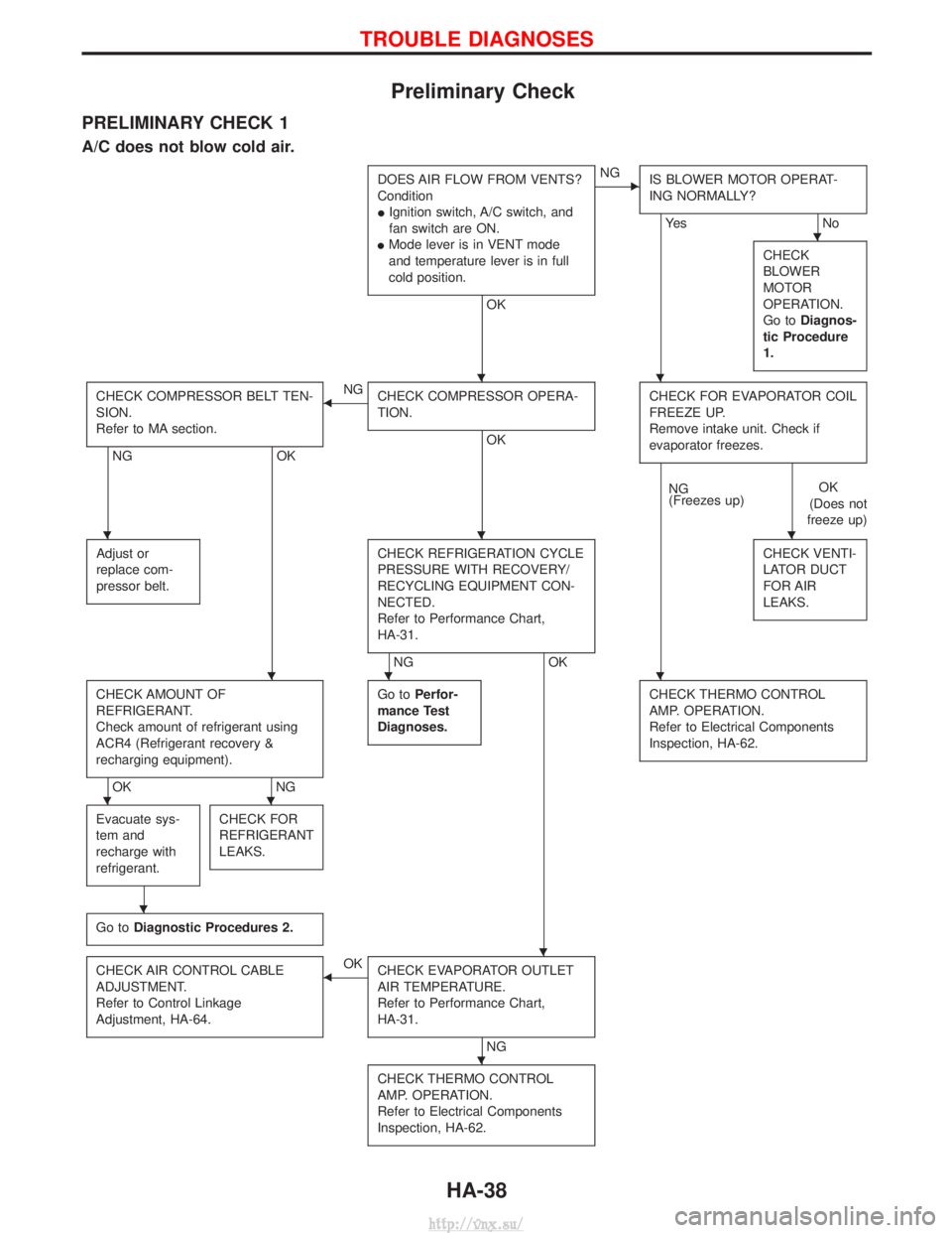
Preliminary Check
PRELIMINARY CHECK 1
A/C does not blow cold air.
DOES AIR FLOW FROM VENTS?
Condition
IIgnition switch, A/C switch, and
fan switch are ON.
I Mode lever is in VENT mode
and temperature lever is in full
cold position.
OK
ENG
IS BLOWER MOTOR OPERAT-
ING NORMALLY?
Ye s N o
CHECK
BLOWER
MOTOR
OPERATION.
Go to Diagnos-
tic Procedure
1.
CHECK COMPRESSOR BELT TEN-
SION.
Refer to MA section.
NG OK
FNG
CHECK COMPRESSOR OPERA-
TION.
OK CHECK FOR EVAPORATOR COIL
FREEZE UP.
Remove intake unit. Check if
evaporator freezes.
NG
(Freezes up)
OK
(Does not
freeze up)
Adjust or
replace com-
pressor belt.
CHECK REFRIGERATION CYCLE
PRESSURE WITH RECOVERY/
RECYCLING EQUIPMENT CON-
NECTED.
Refer to Performance Chart,
HA-31.
NG OK CHECK VENTI-
LATOR DUCT
FOR AIR
LEAKS.
CHECK AMOUNT OF
REFRIGERANT.
Check amount of refrigerant using
ACR4 (Refrigerant recovery &
recharging equipment).
OK
NGGo to
Perfor-
mance Test
Diagnoses.
CHECK THERMO CONTROL
AMP. OPERATION.
Refer to Electrical Components
Inspection, HA-62.
Evacuate sys-
tem and
recharge with
refrigerant.CHECK FOR
REFRIGERANT
LEAKS.
Go to Diagnostic Procedures 2.
CHECK AIR CONTROL CABLE
ADJUSTMENT.
Refer to Control Linkage
Adjustment, HA-64.FOK
CHECK EVAPORATOR OUTLET
AIR TEMPERATURE.
Refer to Performance Chart,
HA-31.
NG
CHECK THERMO CONTROL
AMP. OPERATION.
Refer to Electrical Components
Inspection, HA-62.
H
HH
HHH
HHH
HH
H
H
H
TROUBLE DIAGNOSES
HA-38
http://vnx.su/
Page 1436 of 1833
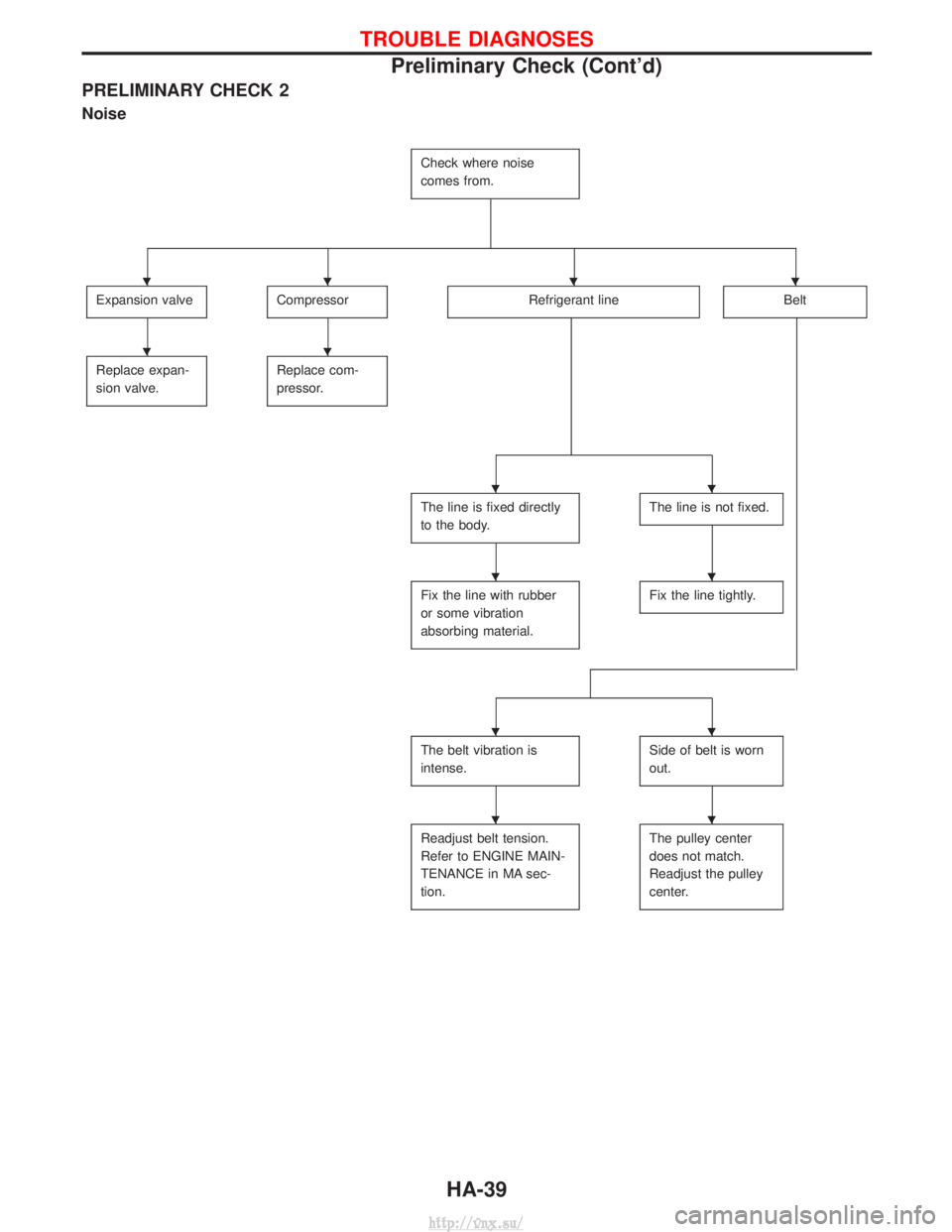
PRELIMINARY CHECK 2
Noise
Check where noise
comes from.
Expansion valveCompressorRefrigerant lineBelt
Replace expan-
sion valve.Replace com-
pressor.
The line is fixed directly
to the body.The line is not fixed.
Fix the line with rubber
or some vibration
absorbing material.Fix the line tightly.
The belt vibration is
intense.Side of belt is worn
out.
Readjust belt tension.
Refer to ENGINE MAIN-
TENANCE in MA sec-
tion.The pulley center
does not match.
Readjust the pulley
center.
HHHH
HH
HH
HH
HH
HH
TROUBLE DIAGNOSES
Preliminary Check (Cont'd)HA-39
http://vnx.su/
Page 1462 of 1833
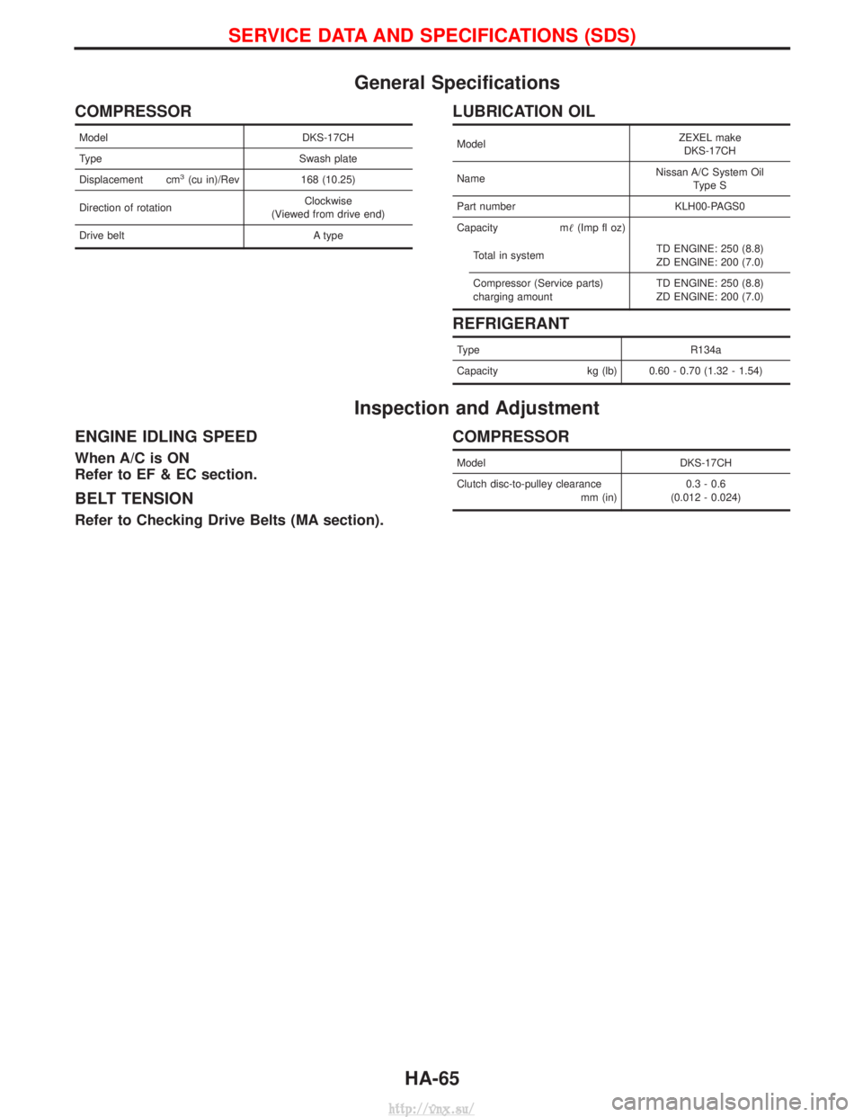
General Specifications
COMPRESSOR
ModelDKS-17CH
Type Swash plate
Displacement cm
3(cu in)/Rev 168 (10.25)
Direction of rotation Clockwise
(Viewed from drive end)
Drive belt A type
LUBRICATION OIL
ModelZEXEL make
DKS-17CH
Name Nissan A/C System Oil
Type S
Part number KLH00-PAGS0
Capacity m (Imp fl oz)
Total in system TD ENGINE: 250 (8.8)
ZD ENGINE: 200 (7.0)
Compressor (Service parts)
charging amount TD ENGINE: 250 (8.8)
ZD ENGINE: 200 (7.0)
REFRIGERANT
Type
R134a
Capacity kg (lb) 0.60 - 0.70 (1.32 - 1.54)
Inspection and Adjustment
ENGINE IDLING SPEED
When A/C is ON
Refer to EF & EC section.
BELT TENSION
Refer to Checking Drive Belts (MA section).
COMPRESSOR
Model DKS-17CH
Clutch disc-to-pulley clearance mm (in)0.3 - 0.6
(0.012 - 0.024)
SERVICE DATA AND SPECIFICATIONS (SDS)
HA-65
http://vnx.su/