Page 25 of 53
Removal and Installation
SEM203HA
CAMSHAFTZD
EM-6003
Page 26 of 53
Inspection
VISUAL INSPECTION OF VALVE LIFTER AND
ADJUSTING SHIM
+Check if surfaces of valve lifter and adjusting shim have any
wear or cracks.
+Replace valve lifter or adjusting shim if necessary.
+Select the thickness of adjusting shim so that valve clearance
is the standard when replacing. Refer to 6005, ªAdjust-
mentsº.
VALVE LIFTER OUTER DIAMETER
Measure the outer diameter of the valve lifter with a micrometer.
Standard: 34.450 - 34.465 mm (1.3563 - 1.3569 in)
LIFTER GUIDE INNER DIAMETER
Measure the lifter guide inner diameter of the cylinder head with
an inside micrometer.
Standard: 34.495 - 34.515 mm (1.3581 - 1.3589 in)
VALVE LIFTER CLEARANCE CALCULATIONS
Clearance = Lifter guide inner diameter þ Valve lifter outer diam-
eter
Standard: 0.030 - 0.065 mm (0.0012 - 0.0026 in)
If it exceeds the standard value, refer to the outer diameter and
inner diameter standard values and replace valve lifter and/or
cylinder head.
SEM160D
FEM018
PBIC0367E
CAMSHAFTZD
EM-6004
Page 27 of 53

Adjustments
NOTE:
Adjust valve clearance while engine is cold.
+Remove the adjusting shim for parts which are outside the
specified valve clearance.
1. Remove the spill tube. Refer to ªBASIC SERVICE PROCE-
DUREº in EC section.
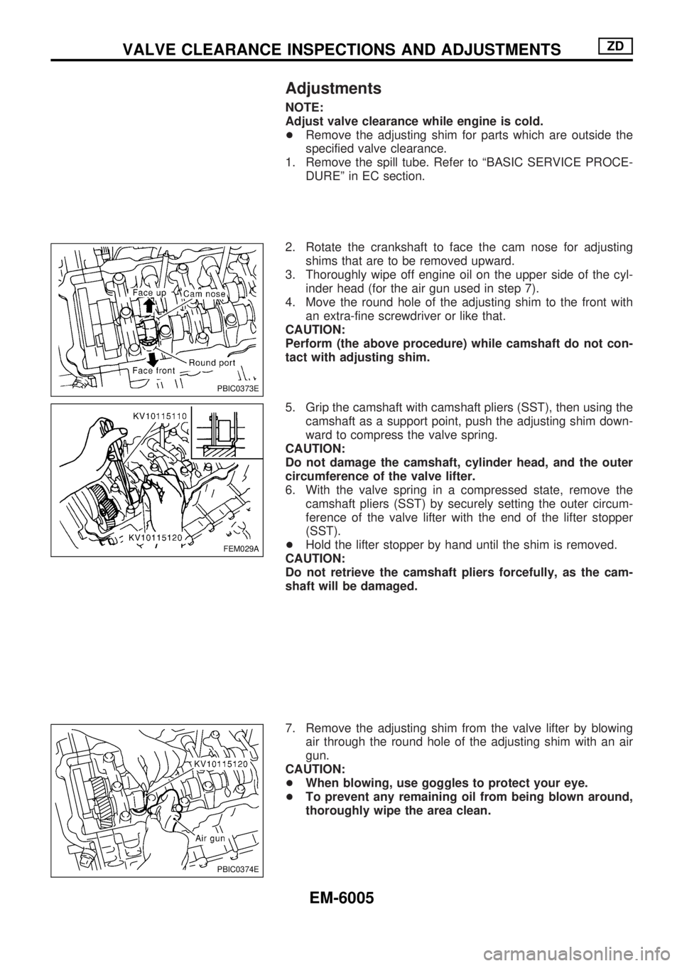
2. Rotate the crankshaft to face the cam nose for adjusting
shims that are to be removed upward.
3. Thoroughly wipe off engine oil on the upper side of the cyl-
inder head (for the air gun used in step 7).
4. Move the round hole of the adjusting shim to the front with
an extra-fine screwdriver or like that.
CAUTION:
Perform (the above procedure) while camshaft do not con-
tact with adjusting shim.
5. Grip the camshaft with camshaft pliers (SST), then using the
camshaft as a support point, push the adjusting shim down-
ward to compress the valve spring.
CAUTION:
Do not damage the camshaft, cylinder head, and the outer
circumference of the valve lifter.
6. With the valve spring in a compressed state, remove the
camshaft pliers (SST) by securely setting the outer circum-
ference of the valve lifter with the end of the lifter stopper
(SST).
+Hold the lifter stopper by hand until the shim is removed.
CAUTION:
Do not retrieve the camshaft pliers forcefully, as the cam-
shaft will be damaged.
7. Remove the adjusting shim from the valve lifter by blowing
air through the round hole of the adjusting shim with an air
gun.
CAUTION:
+When blowing, use goggles to protect your eye.
+To prevent any remaining oil from being blown around,
thoroughly wipe the area clean.
PBIC0373E
FEM029A
PBIC0374E
VALVE CLEARANCE INSPECTIONS AND ADJUSTMENTSZD
EM-6005
Page 28 of 53

8. Remove the adjusting shim by using a magnetic holder.
9. Measure the thickness of the adjusting shim using a
micrometer.
+Measure near the center of the shim (the part that touches
the camshaft).
10. Select the new adjusting shim from the following methods.
Calculation method of the adjusting shim thickness:
t=t
1+(C1þC2)
t = Thickness of replacement adjusting shim
t
1= Thickness of removed adjusting shim
C
1= Measured valve clearance
C
2= Specified valve clearance
When engine is cold [Approximately 20ÉC (68ÉF)]
0.35 mm (0.014 in)
+New adjusting shims have the thickness stamped on the rear
side.
Stamped Shim thickness mm (in)
2.35
2.40
.
.
.
3.052.35 (0.0925)
2.40 (0.0945)
.
.
.
3.05 (0.1201)
+The thickness of the adjusting shim ranges from 2.35 to 3.05
mm (0.0925 to 0.1201 in), where in the space of 0.05 mm
(0.0020 in). There are 15 types of shims available.
11. Fit the selected adjusting shim to the valve lifter.
CAUTION:
Place the stamped side of the adjusting shim to the valve
lifter.
PBIC0375E
SEM145D
JEM184G
VALVE CLEARANCE INSPECTIONS AND ADJUSTMENTSZD
Adjustments (Cont'd)
EM-6006
Page 29 of 53
12. Compress the valve spring using the camshaft pliers (SST)
and remove the lifter stopper (SST).
13. Rotate the crankshaft 2 to 3 times by hand.
14. Confirm that the valve clearance is within the specification.
Valve clearance:
When engine is cold [Approximately 20ÉC (68ÉF)]
Intake and exhaust
0.30 - 0.40 mm (0.012 - 0.016 in)
15. Install remaining parts in the reverse order of removal.
FEM029A
VALVE CLEARANCE INSPECTIONS AND ADJUSTMENTSZD
Adjustments (Cont'd)
EM-6007
Page 30 of 53
Disassembly and Assembly
FEM081A
CYLINDER HEADZD
EM-6008
Page 31 of 53
Valve
VALVE CLEARANCE
Unit: mm (in)
ItemsCold*
Intake and exhaust0.30 - 0.40 (0.012 - 0.016)
*: Approximately 20ÉC (68ÉF)
AVAILABLE SHIMS
Thickness mm (in) Identification mark
2.35 (0.0925) 2.35
2.40 (0.0945) 2.40
2.45 (0.0965) 2.45
2.50 (0.0984) 2.50
2.55 (0.1004) 2.55
2.60 (0.1024) 2.60
2.65 (0.1043) 2.65
2.70 (0.1063) 2.70
2.75 (0.1083) 2.75
2.80 (0.1102) 2.80
2.85 (0.1122) 2.85
2.90 (0.1142) 2.90
2.95 (0.1161) 2.95
3.00 (0.1181) 3.00
3.05 (0.1201) 3.05
JEM184G
VALVE LIFTER
Unit: mm (in)
Valve lifter outer diameter 34.450 - 34.465 (1.3563 - 1.3569)
Lifter guide inner diameter 34.495 - 34.515 (1.3581 - 1.3589)
Clearance between lifter and lifter guide 0.030 - 0.065 (0.0012 - 0.0026)
SERVICE DATA AND SPECIFICATIONS (SDS)ZD
EM-6009
Page 32 of 53

GENERAL INFORMATION
SECTION
GI
MODIFICATION NOTICE:
+Load suspension for single cab 2WD A-chassis has been terminated.
+Specification for double cab 4WD E-grade has been modified.
+Low-geared final drive has been added to the KA24DE equipped models for the Middle East.
+265/70R16 size tire has been added as an option for Europe.
CONTENTS
CONSULT-II CHECKING SYSTEM..................... 6002
Function and System Application .................... 6002
Nickel Metal Hydride Battery Replacement ..... 6002
Checking Equipment ........................................ 6003
CONSULT-II Data Link Connector (DLC)
Circuit ............................................................... 6003IDENTIFICATION INFORMATION...................... 6004
Model Variation ................................................ 6004
Identification Number ....................................... 6005
Wheels and Tires ............................................. 6007
Dimensions ...................................................... 6008
This modification has been included in production starting with the following vehicle identification numbers
(Chassis number):
For Australia and New Zealand
JN1ADGD22A0040001
JN1ANUD22A0028001
JN1BNUD22A0030001
JN1CDGD22A0040001
JN1CRUD22A0020001
JN1CNUD22A0040001
For the Middle East
JN6DD23S*5A770101
JN6HD23S*5A770101
JN6DD23Y*5A770101
JN6PD23S*5A770101
JN6PD23Y*5A770101
For Europe
JN1CPUD22U0820101
For Israel
JN1CPGD225A707101
JN1CPUD225A707101
GI