Page 1670 of 3870
Fig. 42: Identifying Connector C
-301 C
-303
Courtesy of MITSUBISHI MOTOR SALES OF AMERICA.
Q: Are the wiring harness between remote controlled radio switch (RH)
connector C-301 (terminals 1 and 2) and clock spring connector C-303
(terminals 4 and 5) in good condition?
YES: The procedure is complete.
NO: Repair the wiring harness. The remote controlled radio switch (RH)
should work normally.
INSPECTION PROCEDURE 4: The System does not Recognize the Remote Controlled Radio Switch (LH) Only. <
vehicles with seven speakers >. CIRCUIT OPERATION Refer to INSPECTION PROCEDURE 2
.
2004 Mitsubishi Endeavor LS
2004 BODY & ACCESSORIES Radio With Tape Player & Cd Player - Endeavor
Page 1673 of 3870
Fig. 44: Switch Position Table
Courtesy of MITSUBISHI MOTOR SALES OF AMERICA.
Q: Is the resistance at the left remote controlled radio switch normal?
YES: Go to Step 2.
NO: Replace the remote controlled radio switch (LH).
STEP 2. Check the radio switch (LH) connector C-311 and clock spring
connector C-303 for loose, corroded or damaged terminals, or terminals
pushed back in the connector.
2004 Mitsubishi Endeavor LS
2004 BODY & ACCESSORIES Radio With Tape Player & Cd Player - Endeavor
Page 1674 of 3870
Fig. 45: Identifying Connector C
-303 C
-311
Courtesy of MITSUBISHI MOTOR SALES OF AMERICA.
Q: Is remote controlled radio switch (LH) connector C-311 and clock
spring connector C-303 in good condition?
YES: Go to Step 3.
NO: Repair or replace the connector. The remote controlled radio switch
(LH) should work normally.
STEP 3. Check the wirin
g harness between remote controlled radio switch
connector C-311 (terminals1 and 2) and clock spring connector C-303
(terminals 4 and 5).
2004 Mitsubishi Endeavor LS
2004 BODY & ACCESSORIES Radio With Tape Player & Cd Player - Endeavor
Page 1675 of 3870
Fig. 46: Identifying Connector C
-303 C
-311
Courtesy of MITSUBISHI MOTOR SALES OF AMERICA.
Q: Are the wiring harness between remote controlled radio switch
connector C-311 (terminals 1 and 2) and clock spring connector C-303
(terminals 4 and 5) in good condition?
YES: No action to be taken.
NO: Repair the wiring harness. The remote controlled radio switch (LH)
should work normally.
INSPECTION PROCEDURE 5: No Sound. < Vehicles with Audio Amplifier >.
2004 Mitsubishi Endeavor LS
2004 BODY & ACCESSORIES Radio With Tape Player & Cd Player - Endeavor
Page 1772 of 3870

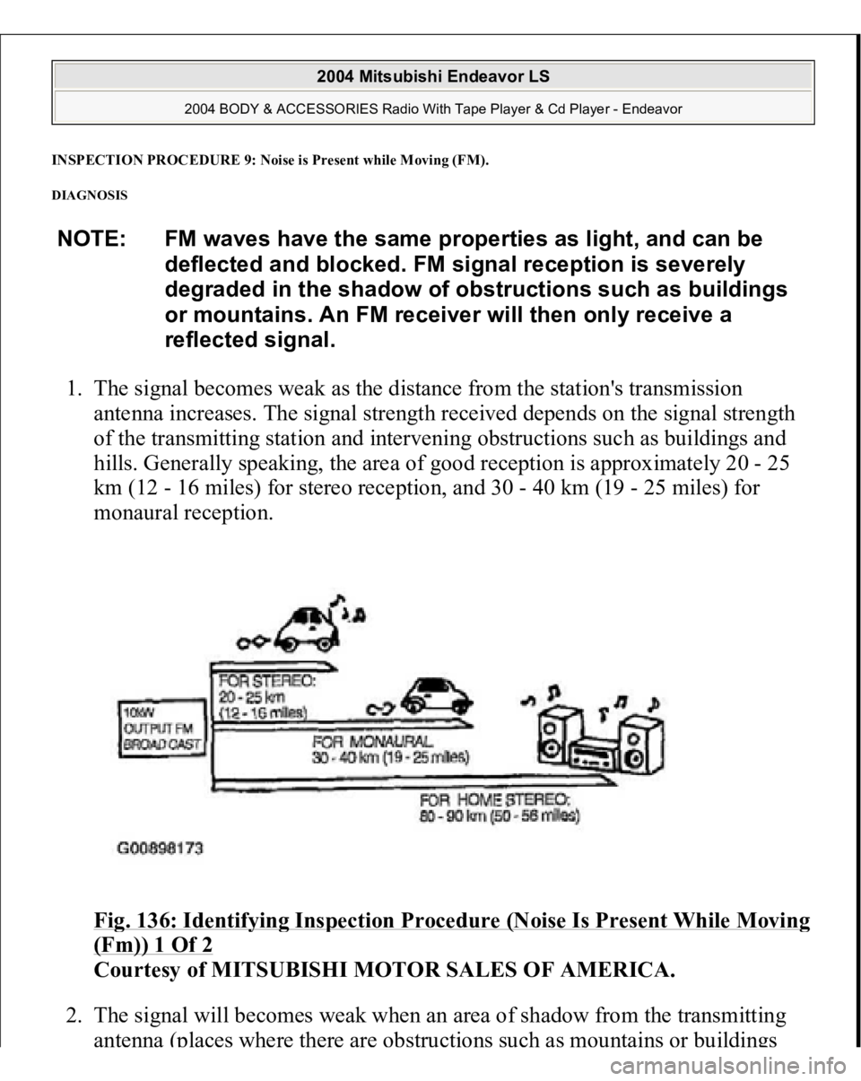
INSPECTION PROCEDURE 9: Noise is Present while Moving (FM)
.
DIAGNOSIS 1. The signal becomes weak as the distance from the station's transmission
antenna increases. The signal strength received depends on the signal strength
of the transmitting station and intervening obstructions such as buildings and
hills. Generally speaking, the area of good reception is approximately 20 - 25
km (12 - 16 miles) for stereo reception, and 30 - 40 km (19 - 25 miles) for
monaural reception.
Fi
g. 136: Identif
ying Ins
pection Procedure (Noise Is Present While Movin
g
(Fm)) 1 Of 2
Courtesy of MITSUBISHI MOTOR SALES OF AMERICA.
2. The signal will becomes weak when an area of shadow from the transmitting
antenna (places
where there are obst
ruct
ions suc
h as m
ountains or buildings
NOTE: FM waves have the same properties as light, and can be
deflected and blocked. FM signal reception is severely
degraded in the shadow of obstructions such as buildings
or mountains. An FM receiver will then only receive a
reflected signal.
2004 Mitsubishi Endeavor LS
2004 BODY & ACCESSORIES Radio With Tape Player & Cd Player - Endeavor
Page 1809 of 3870
Fig. 151: Displaying Memory Button
Courtesy of MITSUBISHI MOTOR SALES OF AMERICA.
3. Check that the speaker, which is displayed on the multi-center display (middle
grade type), sounds (If the memory select "6" button is pressed, the speaker
will be changed).
4. If a button other than the memory select "6" button and "EJECT" button (CD)
is pressed, or the ignition switch is turned to "LOCK" (OFF) position, you will
exit from the speaker test mode.
2004 Mitsubishi Endeavor LS
2004 BODY & ACCESSORIES Radio With Tape Player & Cd Player - Endeavor
Page 1855 of 3870
Fig. 3: Installing M8 X 1.25 mm Bolts In Brake Disc
Courtesy of MITSUBISHI MOTOR SALES OF AMERICA.
<< D>> SELF LOCKING NUT (CONNECTION FOR TIE ROD END) REMOVAL
CAUTION:
Do not remove the nut from the ball joint. Loosen
it and use the special tool to avoid possible
damage to ball joint threads. Hang the special tool with a cord to prevent from
falling.
2004 Mitsubishi Endeavor LS
2004 DRIVELINE/AXLES Front Axle Hub & Axle Shafts - Endeavor
Page 1856 of 3870
1. Install the special tool MB991897 as shown in the figure.
Fig. 4: Installing Special Tool MB991897
Courtesy of MITSUBISHI MOTOR SALES OF AMERICA.
2. Turn the bolt and knob as necessary to make the jaws of special tool
MB991897 parallel, tighten the bolt by hand and confirm that the jaws are still
parallel.
3. Tighten the bolt with a wrench to disconnect the tie rod end and remove the
self lockin
g nut.
NOTE: When adjusting the jaws in parallel, make sure the knob
is in the position shown in the figure.
2004 Mitsubishi Endeavor LS
2004 DRIVELINE/AXLES Front Axle Hub & Axle Shafts - Endeavor